The E
ff
ect of Severe Plastic Deformations on Phase Transitions and Structure of
Solids
Vladimir D. Blank
+, Mikhail Yu. Popov and Boris A. Kulnitskiy
Technological Institute for Superhard and Novel Carbon Materials, Troitsk, Moscow, 108840, Russia
This paper presents data on the study of phase transitions in solids under pressure with shear deformation. Carbon, silicon and zirconium were used as model substances. The studies were carried out by electron microscopy and optical (Raman) spectroscopy. A description of a high pressure diamond anvil shear cell is also provided. [doi:10.2320/matertrans.MF201942]
(Received April 8, 2019; Accepted May 17, 2019; Published July 25, 2019)
Keywords: severe deformation, pressure, shear diamond anvil cell, phase transformations, structure of solids, phase diagram, carbon, fullerens (C60), silicon, zirconium
1. Introduction and Experimental Procedure
The shear pressure method was first proposed and developed by American scientist P.W. Bridgeman in the 1930s, who discovered interesting phenomena occurring with solids under these conditions. Over the past thirty years, interest in the study of solids under the high pressure combined with shear deformation has increased significantly. At present, extensive studies are being carried out on the transformations in highly compressed substances that receive a mechanical perturbation caused by shear.
Thefirst apparatus for shear under pressure was proposed also by P.W. Bridgman and allowed to investigate solids under pressure up to 10.0 GPa.14) Later this method was
actively developed in the USSR under the leadership of L.F. Vereshchagin, who together with E.V. Zubova and G.L. Aparnikov and others proposed several devices for shear under pressure up to 10.0 GPa.5,6) In particular, this method allowed investigating phase transitions by studying the the shear stresspressure dependence. In recent years, these studies have been actively developed in several countries, including Russia (R.Z. Valiev), Japan (Z. Horita), the USA (V. Levitas), and others. The main direction of these studies is the creation of new micro- and nanostructural states in various materials in order to alter their physical properties.7)
The most active work in recent years is carried out at the International Research Center on Giant Straining for Advanced Materials (IRC-GSAm) at Kyushu University, Fukuoka (Japan). Research is conducted on a very wide range of materials, including metal alloys, semiconductors: Si, Ge; carbon and others, that is, bear not only scientific, but also practical interest.8)
Impact of shear under pressure is especially evident in the case of phase transitions, where not only the hysteresis of the transformations changes, but also the equilibrium conditions of the phases, their stability and the possibility of obtaining new structural states, including amorphous ones. With increasing pressure, the effect of shear deformation on a substance will only increase, especially for brittle solids, since under the conditions of strong compression, the possibility of plastic deformation appears. The development
of experimental techniques for studying such processes has drastically changed with the creation of shear pressure diamond anvil cells. This made it possible to study compressed matter not only under pressure, but also directly in the process of shear, including optical and X-ray methods. And most important to significantly expand the range of pressures used up to 150 GPa.
In Technological Institute for Superhard and Novel Carbon Materials (TISNCM), Troitsk, Moscow, Russia, several types of shear pressure diamond anvil cells have been developed, which are successfully used to study phase transitions in solids at pressures up to 150 GPa and a wide temperature range. When studying phase transitions under controlled shear deformation, the effect of pressure self-multiplication was discovered, which is caused by an abrupt change in the elastic Young’s modulus (E) during the transition from one phase to another, with a constant external load.11)This effect
is non-linear and can actively control the pressure in such devices.911)It should be noted that the process of studying a substance at high pressures with shear has its own experimental features that must be taken into account. In particular, this is due to the possible interaction of the test substance with the anvil material. You should also take into account the more strict requirements for the mechanical stability of the diamond anvil when deformation is applied. In a shear diamond anvil cell (SDAC), the sample is loaded without a gasket or in a gasket without a pressure transmitting medium. As a rule, the gasket is made of hardened steel or tungsten, rhenium, etc. The latter provide a large sample thickness and work well in a pressure range greater than 100 GPa. Usually, the gasket is precompressed to a pressure of 0.5 of the planned pressure in the experiment. Then a hole is drilled in the center of the compressed gasket (the diameter of the hole is 0.30.5 of the anvil diameter). A sample is placed in the drilled hole.
Controlled plastic deformation is applied to the loaded sample due to the rotation of one of the anvils around the load application axis. In the case of thefirst-order phase transition, stepwise anomalies appear on the radial pressure distribution curves in the sample (loaded in SDAC), due to a jump in the elastic moduli and volume, due to the phase transition.911)
Since these anomalies are associated with boundaries between different phases, it is possible to determine the
+Corresponding author, vblank@tisnum.ru
pressure of the first-order phase transition from the curves of the radial distribution of pressure in the sample. We have successfully applied this technique to study phase transitions in fullerite10,1315) and also discovered a number of phase
transitions in carbon nanotubes, including the formation of a superhard phase.13,1618)
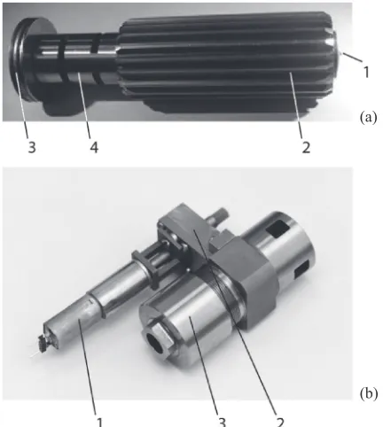
In thefirst works in 19871992 the maximum pressures at which the specimens in SDAC were studied under shear conditions reached 96 GPa.1120)To date, experiments with a shear are carried out up to 130 GPa.21)To avoid displacement and tilting of diamond anvils under load, and to increase the pressure at which it is possible to investigate phase transitions in samples under conditions of non-hydrostatic loading and large shear deformation, the following changes have been made to the SDAC design described in Refs. 911, 19, 20). SDAC is depicted in Fig. 1(a), (b).
Rotation to the movable anvil (a1) is transmitted through a toothed shape piston (a2) using an electric motor (b1) through a gearbox (b3). The load on the anvils is applied with the help of a nut (b2) and is transmitted to the anvil through the thrust bearing (a3) and spring (a4).
An adjustment device, which ensured the perpendicu-larity of the coulting plane of the load application axis, was removed from the cell described in papers.19,20) Existing technical capabilities allow obtaining the culet to the anvil base parallelism better than 1 micron skew on 50 microns of surface.
The adjustment device for the alignment of the anvils and the camera rotation axes was also removed. Instead, a removable centering device is used to set anvils and carbide supports on the cell rotation axis. The centering device is manufactured with the same precision as the chamber piston. The anvil tops (or, respectively, the holes under the anvils in
the stands) arefixed in the centering device, which is inserted into the cell between the anvils.
Anvils and hard-alloy supports are glued to the piston and cylinder of the chamber with epoxy resin under load, which eliminates deviations from parallelism.
After the resin has solidified, the centering device is removed.
The diamond anvils of the traditional form are mounted either on supports made of hard alloy (Fig. 1), or the anvils with a conical support are mounted in hard-alloy supports of the design proposed by R. Boehler (“Boehler-Almax anvils”).22) The latter provide a larger aperture, which is
important for optical research, in particular, for the study of Raman scattering.
The leverage loading system is removed. The load on the anvil is applied as in the cell design of M.I. Yeremets,23)
engineered for pressures greater than 100 GPa.
The parallelism of the cutlets to the base of the stand is controlled and does not exceed 1 micron skew on 50 microns.
The above changes made to the cell design, allowed to increase the pressure in the sample during the shear to 150 GPa.21)
In the present paper, the structure of different forms of carbon (C60, graphite, diamond, and nanotubes), as well as
silicon and zirconium after pressure treatment under conditions of severe plastic deformations in a high-pressure cell with a shear, was studied by TEM and Raman spectroscopy. It is established that in the same conditions of processing by pressure and deformation the listed materials behave differently, that in C60 and Zr
trans-formation-deformation bands are formed, containing high-pressure phases. Depending on the processing conditions, graphite can turn into diamond and multi-walled pipes and onions. Diamond powder and multi-walled nanotubes are also transformed into onions. A new carbon phase diagram up to 130 GPa has been proposed. Shear bands were not found in silicon, but the formation of high-pressure phases (SiIII and SiIV) was established.
Samples of the original C60 fullerene with face-centered
crystal lattice were examined by methods of high-resolution transmission electron microscopy and electron energy loss spectroscopy after their treatment in SDAC. A distinctive feature of all the structures studied were deformation bands. We observed alternating parallel stripes, dark (thicker areas) and light - thin sections with holes. Sometimes at the same time, two systems of stripes were visible, while they intersected at different angles. Fragments of crystal structures located both in the ridges and in the depressions were analyzed. The average frequency of such bands varied from sample to sample in the range from 10 to 50 nm. EELS spectra of the sample showed a peak centered on 287 eV, corresponding to the molecular crystalline nature of C60.
This indicates that C60 molecules are preserved in the
sample. Figure 2 shows shear transformation-deformation bands. The analysis showed that the bands contain shear-strain-induced nanocrystals of linearly polymerized fullerene and polytypes, as well as the triclinic, monoclinic, and hcp phases of C60, fragments of amorphous structures, and voids.
Consequently, after pressure release, the plastic strain retains (a)
(b)
[image:2.595.62.278.70.311.2]high pressure phases. The presence of these phases in the sample after processing is potentially important for their applications.
Localized shear deformation initially seems contradictory because high pressure phases of C60 are stronger than the
initial low pressure phase. However, this was explained by transformation-induced plasticity during localized phase transformations. It occurs due to a combination of applied stresses and internal stresses from a volume reduction during phase transformations. Localized phase transformations and plastic shear deformation promote each other, which produce positive mechanochemical feedback and cascading trans-formation-deformation processes. Since the plastic shear in a band is much larger than is expected based on the torsion angle, five phase transformations occur in the same region with no transformation outside the band. The results demonstrate that transformation kinetics cannot be analyzed in terms of prescribed shear, and methods to measure local shear should be developed.43,44)
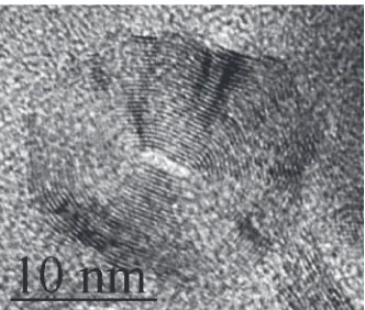
Carbon onions were formed in graphite after treatment in SDAC under axial pressure combined with shear deformation at room temperature Fig. 3. The onions were ranging in size from 12 nm to 12 µm and HREM studies have shown that the amount of their concentric shells tended to increase with
pressure and deformation growth. Raman spectra were taken from large-size onions. Narrow bands found between 1400 and 1550 cm¹1 correspond to fullerene-related carbon materials. The splitting of the pentagonal pinch mode 14461489 cm¹1 is considered to be connected with the formation of heptagons.
In the processing of graphite, diamond, and multiwalled carbon nanotubes under high pressures, the instability of diamond was demonstrated in the 55115 GPa pressure range, at which onion-like structures are formed. In addition, the formation of interlayer sp3-bonds in carbon
nanostruc-tures with a decrease in their volume has been studied theoretically. It has been found that depending on the structure, the bonds between the layers can be preserved or broken during unloading.45,47)
2. Carbon Phase Diagram
As shown in Ref. 24), a single crystal of graphite compressed along the c axis irreversibly transforms into hexagonal diamond at a pressure of 12 GPa and a temperature of more than 1000°C. This phase transition was studied at room temperature by X-ray diffraction under pressure in Ref. 25), where it was observed at a pressure of 14 GPa in the case of compression along the c axis, but was reversible® when unloaded, hexagonal diamond turned back into graphite. Under hydrostatic loading, graphite does not convert to diamond at least up to a pressure of 80 GPa.26)
Graphite irreversibly transforms into diamond at room temperature at a pressure of 17 GPa in the case of compression along the c axis and application of shear deformation, as shown in Ref. 27). Without the activation by the shear deformation, diamond can be observed in graphite samples after pressure at least 70 GPa.28)
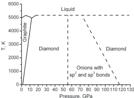
In Refs. 21, 29, 30), we continued to study the phase diagram of carbon up to 130 GPa using the concept of shear under pressure. We found that in the area of pressures 55 115 GPa there is an area of instability of the diamond. In this area, graphite under the influence of shear deformation does not turn into diamond, but into more dense onion-like
(a) (b)
Fig. 2 C60: (a) - bands and (b) - high pressure phase fragments.43)
[image:3.595.124.477.69.265.2] [image:3.595.87.253.619.760.2]structures. Diamond also transforms into the same structures in the detected region under the influence of laser radiation. When the pressure rises above 115 GPa, diamond is formed again when graphite is shifted under pressure. Based on experimental and model data, a new carbon phase diagram was constructed (Fig. 4).
3. Polymerization of C60under Pressure
Under hydrostatic loading conditions, as shown in Ref. 31), the FCC structure of fullerite exists up to 20 GPa. In this case, already at pressures starting from 0.4 GPa, the free rotation of the C60 molecules observed in the initial
molecular crystal stops.32) With increasing pressure, the
optical properties of fullerite significantly change.33,36) With
an increase of the hydrostatic pressure of up to 15 GPa, the absorption threshold (Eg) decreases to 1 eV and with a further
increase to 25 GPa remains almost unchanged.33) At a pressure of 25 GPa, Egincreases dramatically to 1.5 eV. This
value is retained after relieving pressure. The transparency of fullerites at high pressures was noted in Refs. 34, 35); however, transparency was not observed under hydrostatic loading in Ref. 36).
In addition to X-ray data, RS Roman spectroscopy and IR infrared spectroscopy studies of fullerites at high pressures were carried out. It follows from the IR spectra that fullerene molecules remain at least up to a pressure of 20 GPa.37)As
found in Refs. 37, 38), the lowest-frequency IR active molecular mode at 526 cm¹1 decreases in frequency with
increasing pressure, while the other modes grow. This anomalous behavior of the 526 cm¹1 mode is explained by
the formation of an additional (to van der Waals) intermo-lecular interaction in fullerite. In accordance with the data of Ref. 39), as the pressure increases, polymerization of C60
molecules is observed, which increases with pressure rise. Significant changes are also observed in the Raman spectra. The range of 14001800 cm¹1was studied in detail.33,35,40,41) With increasing pressure, the frequency of the bands in the spectra also grows, the width of the lines increases, and at pressures greater than 19 GPa, the bands merge into one.35)
According to the RS data, it was found that up to pressures of 25 GPa, all changes in the spectra are reversible. When
the pressure was removed, the spectra corresponded to the spectra of the initial fullerene. After pressures above 25 GPa, the changes become irreversible. According to the authors of Refs. 33, 35, 41), the spectra correspond either to diamond-like carbon (ta-C),35) or amorphous graphite-like carbon (a-C),41) or to a new carbon phase.33) In these papers, the insufficiently substantiated conclusion was made that C60
molecules collapsed under pressure. We12,13)discovered and investigated in SDAC two new fullerite phases obtained under pressure under conditions of controlled shear deformation at 7 and 18 GPa, which persist after pressure release. One of them is superior to diamond in hardness and elastic moduli.
We recently found a catalyst (CS2) that activates the C60
3D polymerization process under shear conditions under pressure.1542)The presence of a catalyst made it possible to
reduce the pressure of the ultrahard fullerite formation from 18 to 67 GPa at room temperature. It is significant that if the catalyst remains in the sample after polymerization, then it is possible to initiate the depolymerization process also under shear conditions under pressure during the pressure relief process.6)
4. Zirconium Treatment
Structural studies were performed in Zr treated under conditions of deformation under pressure. Our research comprises two techniques: studies in a high-pressure shear cell, and during a hydrostatic extrusion process. In the samples pressure-treated under shear conditions, deformation bands were found and their orientation was determined. Figure 5 shows two types of bands in Zr: short, associated with the splitting of the single-crystal portion of the sample into misoriented fragments (a) and long (b), in which both the initial phase -¡and the high pressure phase are present
-½. It was found that under two types of deformation used in the present work, only one of the two orientational relationships (OR) known in literature for the mutual orientation of the¡- and½-phases occurs, which is explained by the introduction of small amounts of oxygen into the
¡-lattice. In the process of shear deformation, oxygen penetrates into the Zr lattice, and baddeleyite-ZrO2is formed.
The mutual orientation of the ¡- and ½-phases with baddeleyite is established.
Fig. 4 New carbon phase diagram.45)
(a) (b)
[image:4.595.55.281.68.234.2] [image:4.595.306.543.618.731.2]5. Silicon Treatment
Due to its unique physicochemical properties, silicon is of great interest for scientific research and practical applications. Silicon was treated with a pressure of 9.5 GPa under conditions of shear deformation at an angle of 15° in a chamber of diameter of 1.5 mm.46) It is known that at atmospheric pressure, the silicon has a cubic diamond structure (SiI) with the lattice parameter a=0.543 nm. At elevated pressures, 11 other crystalline phases of Si have been identified by calculation and from pressure cell experiments.51) High pressure phases are of interest to our
research, which are referred Si-III or Kasper phase with the cubic structure with parameter 0.663 nm52) and Si-IV or
lonsdaleite - hexagonal structure with lattice parameters a=0.386 nm, c=0.631 nm. These phases are metastable phases, which persist after the pressure release (unloading). TEM studies showed strong grinding of silicon after processing. No shear bands were detected. TEM methods, in addition to the initial SiI phase, also revealed high-pressure phases SiIII and SiIV. Figure 6 shows twins in silicon along the {111} plane. The rectangles denote fragments of the boundaries between the twins, in which the traditional packing for SiI ABCABC is changed to ABABAB, which corresponds to the hexagonal silicon phase, SiIV.49)
6. Discussion
Shear bands (i.e., regions in which inelastic shear deformation significantly localizes and exceeds the deforma-tion in the surrounding material) are broadly observed in all types of materials (metals, rocks, ceramics, ionic crystals, organic compounds and polymers, polycrystalline alloys, and metallic glasses).53) There are various explanations for the
existence of deformation bands. So, it is believed that the interference of unloading waves creates areas of tensile stresses. Cracks originate in those areas where the magnitude of tensile stresses exceeds the dynamic strength of the material. As the crack deepens, the intensity of tensile stresses decreases, and the cracks develop into adiabatic shear bands. The phenomenon of narrow deformation bands is explained by the narrow width of the zone of interference of unloading waves, where shear bands are formed at negative pressures.50)In the present work, they were formed
in C60and in Zr. No deformation bands were detected in other
carbon materials and silicon. Grinding and fragmentary -phase transformations occur.
7. Conclusion
For application of controlled plastic deformation to the specimen at high pressures, a shear diamond anvil cell (SDAC) was developed. The structure of different forms of carbon (C60, graphite, diamond, and nanotubes), as well as
silicon and zirconium after pressure treatment under conditions of large plastic deformations in the high-pressure cell with a shift, was studied by TEM and Raman spectroscopy. It is established that the listed materials in the same conditions of processing by pressure and deformation behave differently, that in C60 and Zr transformation-deformation bands are formed, containing high-pressure phases. Depending on the processing conditions, graphite can turn into diamond and multi-walled pipes and onions. Diamond powder and multi-walled nanotubes are also transformed into onions. A new carbon phase diagram up to 130 GPa has been proposed. Shear bands were not found in silicon, but the formation of high-pressure phases (SiIII and SiIV) was established.
REFERENCES
1) P.W. Bridgman:Studies in Large Plastic Flow and Fracture. 2) P.W. Bridgman:Phys. Rev.48(1935) 825.
3) P.W. Bridgman:J. Appl. Phys.8(1937) 328. 4) P.W. Bridgman:Proc. Am. Acad. Sci.71(1937) 387.
5) L.F Vereschagin, E.V. Zubova and V.A. Shapochkin: Priboru I Technika Eksperimenta5(1960) 8993.
6) L.F. Vereschagin, E.V. Zubova, K.P. Buurdina and G.Z. Aparnikov: Dokl. Acad. Nayk SSSR196(1971) 817818.
7) K. Edalati, Y. Ikoma and Z. Horita (eds.): Proc. of the International Workshop on GSAM2015, (Fukuoka, Japan, on September 36). 8) Z. Horita: Proc. of Inter. Workshop on GSAM2015, (Fukuoka, Japan,
2016) 62.
9) V.D. Blank, Y.Y. Boguslavsky and M.I. Eremets: Tech. Phys.87(1984) 922.
10) V.D. Blank and S.G. Buga: Instrum. Exp. Tech. (1) (1993) 205. 11) V.D. Blank, Y.Y. Boguslavsky, M.I. Eremets, E.S. Itskevich, S.Y.
Konyaev, A.M. Shirokov and E.I. Estrin: Sov. Phys. JETP87(1984) 922.
12) V. Blank, M. Popov, S. Buga, V. Davydov, V. Agafonov, R. Ceolin, H. Szwarc and A. Rassat:Phys. Lett. A188(1994) 281.
13) M. Popov, M. Kyotani and Y. Koga:Diamond Relat. Mater.12(2003) 833.
14) M.A.M. Popov, A. Kirichenko, B. Kulnitskiy, I. Perezhogin, E. Tyukalova and V. Blank:J. Mater. Res.30(2015) 1772.
15) M. Popov, V. Mordkovich, S. Perfilov, A. Kirichenko, B. Kulnitskiy, I. Perezhogin and V. Blank:Carbon76(2014) 250.
16) M. Popov, M. Kyotani, Y. Koga and R.J. Nemanich:Phys. Rev. B65
(2002) 033408.
17) A.M. Pankov, A.S. Bredikhina, B.A. Kulnitskiy, I.A. Perezhogin, E.A. Skryleva, Y.N. Parkhomenko, M.Y. Popov and V.D. Blank:AIP Adv.7
(2017) 085218.
18) E.Y. Pashkin, A.M. Pankov, B.A. Kulnitskiy, I.A. Perezhogin, A.R. Karaeva, V.Z. Mordkovich, M.Y. Popov, P.B. Sorokin and V.D. Blank: Appl. Phys. Lett.109(2016) 081904.
19) V.D. Blank and A.J. Zerr:High Press. Res.8(4) (1992) 567. 20) I.A. Barabanov, V.D. Blank and S. Konyaev: Pribory i Technika
Eksperimenta2(1987) 176.
21) V.D. Blank, V.D. Churkin, B.A. Kulnitskiy, I.A. Perezhogin, A.N. Kirichenko, V.N. Denisov, S.V. Erohin, P.B. Sorokin and M.Y. Popov: Nanotechnology29(2018) 115603.
22) R. Boehler and K. Hantsetters:High Press. Res.24(2004) 391.
(a) (b)
[image:5.595.49.288.70.181.2]23) M.I. Eremets:J. Raman Spectrosc.34(2003) 515.
24) F.P. Bundy and J.S. Kasper:J. Chem. Phys.46(1967) 3437. 25) T. Yagi, W. Utsumi, M. Yamakata, T. Kikegawa and O. Shimomura:
Phys. Rev. B46(1992) 6031.
26) A. Goncharov: Sov. Phys. JETP71(1990) 1025.
27) V. Aksenenkov, V.D. Blank, A. Borovikov, V. Danilov and K. Kosorezov: Physics-Doklady, Academy of Sciences of USSR 39
(1994) 700.
28) T.L. Schindler and Y.K. Vohra: J. Phys. Condens. Matter 7(1995) L637.
29) V.D. Blank, V.D. Churkin, B.A. Kulnitskiy, I.A. Perezhogin, A.N. Kirichenko, V.N. Denisov, S.V. Erohin, P.B. Sorokin and M.Y. Popov: Mater. Today Proc.5(2018) 26179.
30) V.D. Blank, V.D. Churkin, B.A. Kulnitskiy, I.A. Perezhogin, A.N. Kirichenko, S.V. Erohin, P.B. Sorokin and M.Y. Popov: Crystals8
(2018) 68.
31) S.J. Duclos, K. Brister, R.C. Haddon, A.R. Korten and F.A. Thiel: Nature351(1991) 380.
32) G.A. Samara, J.E. Shirber, B. Morosin, L.V. Hansen, D. Loy and A.P. Sylvester:Phys. Rev. Lett.67(1991) 3136.
33) F. Moshary, N.H. Chen, I.F. Silvera, C.A. Brown, H.C. Dorn, M.S. Vries and D.S. Bethune:Phys. Rev. Lett.69(1992) 466.
34) M.N. Regueiro, P. Monceau and J.-U. Hodeau:Nature355(1992) 237. 35) C.S. Yoo and W.J. Nellis:Chem. Phys. Lett.198(1992) 379. 36) D.W. Snoke, K. Syassen and A. Mittelbach:Phys. Rev. B47(1993)
4146.
37) D.D. Klug, J.A. Howard and D.A. Wilkinson:Chem. Phys. Lett.188
(1992) 168.
38) K. Aoki, H. Yamawaki, Y. Kakudate, M. Yoshida, S. Usuba, H. Yokoi, S. Fujiwara, Y. Bae, R. Malhotra and D. Lorents:J. Phys. Chem.95
(1991) 9037.
39) H. Yamawaki, M. Yoshida, Y. Kakudate, S. Usuba, H. Yokoi, S. Fujiwara, K. Aoki, R. Ruoff, R. Malhotra and D. Lorents:J. Phys.
Chem.97(1993) 11161.
40) S.H. Tolbert, A.P. Alivisatos, H.E. Lorenzana, M.B. Kruger and R. Jeanlor:Chem. Phys. Lett.188(1992) 163.
41) Y.S. Raptis, D.W. Snoke, K. Syassen, S. Rath, P. Bernier and A. Zahab: High Press. Res.9(1992) 41.
42) M. Popov, B. Kulnitskiy, I. Perezhogin, V. Mordkovich, D. Ovsyannikov, S. Perfilov, L. Borisova and V. Blank:Fuller. Nanotub. Carbon Nanostruct.26(2018) 465.
43) B.A. Kulnitskiy, V.D. Blank, V.I. Levitas, I.A. Perezhogin, M.Yu. Popov, A.N. Kirichenko and E.V. Tyukalova:Mater. Res. Express3
(2016) 045601.
44) V.D. Blank, Ye.V. Tatyanin and B.A. Kulnitskiy: Phys. Lett. A225
(1997) 121126.
45) V.D. Blank, V.D. Churkin, B.A. Kulnitskiy, I.A. Perezhogin, A.N. Kirichenko, S.V. Erohin, P.B. Sorokin and M.Yu. Popov:Crystals8
(2018) 68.
46) V.D. Blank and B.A. Kulnitskiy:High Press. Res.15(1996) 3142. 47) V.D. Blank, V.N. Denisov, A.N. Kirichenko, B.A. Kulnitskiy, S.Yu.
Martushov, B.N. Mavrin and I.A. Perezhogin: Nanotechnology 18
(2007) 345601.
48) A.A. Yaroslavzev, I.A. Evdokimov, B.A. Kulnitskiy, I.A. Perezhogin, V.D. Blank, I.V. Pakhomov and V.V. Denisov:Mater. Res. Express6
(2019) 046506.
49) B. Kulnitskiy, M. Annenkov, I. Perezhogin, M. Popov, D. Ovsyannikov and V. Blank:Acta Crystallogr. Sec. BB72(2016) 733737. 50) A.F. Belikova, S.N. Buravova and Y.A. Gordopolov:Tech. Phys.58
(2013) 302304.
51) A. George:Properties of Crystalline Silicon, ed. by R. Hull, (INSPEC, the Institution of Electrical Engineers, London, 1999) p. 104. 52) R.H. Wentorf and J.S. Kasper:Science139(1963) 338.