Weibull Statistics for Evaluating Failure Behaviors and Joining
Reliability of Friction Stir Spot Welded 5052 Aluminum Alloy
Chung-Wei Yang
1, Fei-Yi Hung
2, Truan-Sheng Lui
1;*, Li-Hui Chen
1and Jiun-Yu Juo
1 1Department of Materials Science and Engineering, National Cheng Kung University, No. 1, University Road, Tainan 701, Taiwan, R.O.C.
2Institute of Nanotechnology and Microsystems Engineering, Center for Micro/Nano Science and Technology,
National Cheng Kung University, No. 1, University Road, Tainan 701, Taiwan, R.O.C.
Friction stir spot welding (FSSW) was applied to make lap-joints of 5052 rolled (5052-R) aluminum alloys. The resulting microstructural observation, microhardness, tensile shear failure load and failure morphologies are reported, including a brief look into failure behaviors in the present study. The metallurgical bonded TMAZ region with a plastic metal flow is obviously created around the probe, and the microhardness is significantly increased at the TMAZ region for FSSW-joined 5052 aluminum alloys. The FSSW lap-joints with an obvious metallurgical bonded TMAZ region generally display a higher failure load and ductile failure morphologies with dimples fracture. In addition, the failure load of FSSW lap-joints was increased with increasing the probe penetration depth and the welding time. Based on the data fluctuation of tensile shear failure load, the Weibull model provided a statistical analysis method for assessing the minimum failure, the failure mechanism and the joining reliability for the FSSW lap-joints. Through the statistical analysis of the Weibull distribution function, FSSW-joined aluminum alloys with a wear-out failure model are recognized as reliable lap-joints for further engineering application. [doi:10.2320/matertrans.MRA2008341]
(Received September 18, 2008; Accepted October 23, 2008; Published December 25, 2008)
Keywords: friction stir spot welding, aluminum alloy, mechanical properties, failure mechanism, Weibull statistics
1. Introduction
Lightweight aluminum alloys are widely used in automo-tives for the purpose of reducing vehicle weight and fuel consumption. Resistance spot welding (RSW) is generally applied for joining steels in the automotive industries of nowadays. However, RSW process is not suitable for joining
aluminum alloys1) because of its high electrical current
requirements and the inconsistent quality of the final
welds.2,3) Recently, a new solid-state joining technology of
the friction stir spot welding (FSSW), which is a derivative
process of the friction stir welding (FSW),4) has been
developed as a widespread technique and successfully
applied for producing lap-joints of aluminum alloys.5–7)
Compared with the traditional RSW process, FSSW can avoid severe heating and cooling cycles induced during welding process. Furthermore, the heat affected zone (HAZ) and residual stresses associated with the welds are relatively
small.8)Significant performance advantages of the solid-state
approach have made FSSW the preferred method for joining
aluminum alloys.9)Therefore, FSSW as well as FSW is now a
simple and indispensable process to acquire better joining strength and vibration fracture resistance for the lightweight
structural metals.6,7,10,11)
Since the failure of FSSW-joined structural components depends on the stress to approach a critical weakest link of the welding spot, the variability of failure strength is fairly correlated with the welding qualities of joints, including microstructural homogeneity, bond formation and bond
width.12–14)However, few current reports focus on assessing
the failure mechanism of FSSW aluminum alloys under mechanical loading for various probe penetration depth. Furthermore, the effect of microstructural feature on failure probability and joining reliability of FSSW lap-joints still
needs further investigation through a statistical examination.
Since the Weibull statistics15)of survival analysis has been
developed as an engineering design method for metals,
metallic glasses and ceramic coatings,16–20)therefore, the aim
of present study is to evaluate the weldability and failure load of FSSW-joined aluminum alloy under tensile shear tests. The joining reliability and failure mechanism will be examined by the Weibull statistics.
2. Materials and Methods
The base-metal used in this study was a 2 mm-thick 5052-H34 aluminum rolled sheets (5052-R) with chemical com-position of 2.58 Mg, 0.26 Cr, 0.15 Si, 0.05 Mn, and 0.07 Zn (mass%). The sheets were machined into welding samples
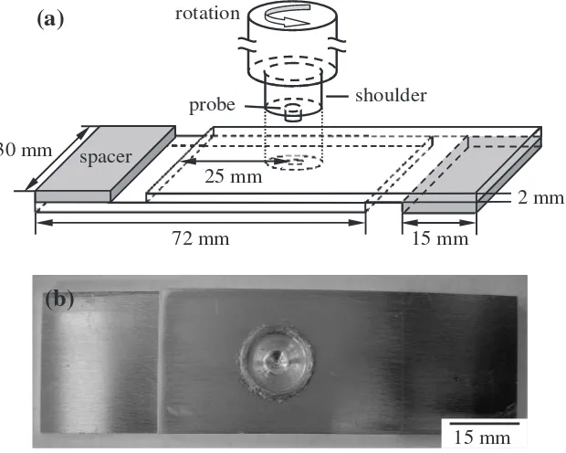
with dimensions of 72 mm (l)30 mm (w). Figure 1(a)
schematically shows a lap-shear specimen used to measure the strength of FSSW-joined 5052-R sheets under a tensile shear loading condition. During FSSW process, a cylindrical rotating tool with a protruding probe plunged into the overlapping 5052-R aluminum sheets. The downward push force and the rotational speed were maintained for an appropriate time to generate frictional heat. The welding tool rotational speed was 1040 rpm, and the downward push force was controlled at about 2.6 kN. The shoulder and probe diameters of the tool were 10 and 3 mm, respectively. Then the generated frictional heat softened the aluminum base-metal and the rotating probe caused material plastic flow in both circumferential and axial directions. The probe pene-tration depth was controlled for 1.0 and 2.5 mm by changing various probe length, and the welding time was maintained under 90, 105 and 135 s.
agent. Then the specimens were etched in a Poulton’s
solution (30 mL HCl + 15 mL HNO3 + 2.5 mL HF +
2.5 mL H2O).21) The microstructural morphologies of
lap-joints were observed by the optical microscopy. To clarify the relationship between failure locations and microhardness variations of the FSSW-joined specimens, microhardness data across the cross-sections of specimens were obtained using a Vickers indenter with a 980 mN load for 10 s dwell time. Each measured microhardness data was an average of three tests.
The failure load of FSSW 5052-R lap-joints was evaluated by tensile shear tests at a crosshead speed of 1.0 mm/s until failure. Figure 1(b) shows a FSSW lap-joined specimen for the tensile shear test. The setting of two spacers, which as represented in light gray regions in Fig. 1(a) with dimensions
of 30 mm (l)15 mm (w) at the both ends of the lap-shear
specimens, were to induce a pure shear to the interfacial plane of the nugget for the joined sheets. For the statistical significance of following Weibull analysis, twenty lap-joined specimens of each joining condition were performed for failure load measurements. The as-failed samples were then examined by a SEM (Philips XL-40 FEG) to observe the fracture surfaces of FSSW lap-joints.
3. Results and Discussion
3.1 Statistical evaluation of failure probability for FSSW lap-joints with the Weibull model
Figure 2 shows the failure load data distribution (repre-sents 20 valid results for each joining condition) and the average value of various FSSW lap-joints measured by the tensile shear tests. The failure load of FSSW-joined speci-mens with the probe penetration depth of 2.5 mm (P2.5-series) and 1.0 mm (P1.0-(P2.5-series) is increased with increasing the welding time. Generally, the FSSW lap-joints with larger
probe penetration depth (P2.5-90s and P2.5-105s) show a higher joining failure load than the other conditions, but
there is little significant difference (p>0:05) for the data
distribution between two P2.5-series joining conditions according to the one-way ANOVA statistical examination. However, the failure load for P1.0-series lap-joints (P1.0-135s) is significantly increased through increasing the
welding time (p<0:05) compared with the P2.5-series
conditions. Furthermore, the failure load is decreased with decreasing the probe penetration depth for the same welding dwell time, and P1.0-105s lap-joints have the lowest average failure load of all.
Previous reports represented that the Weibull statistics15,22)
can be successfully adopted to evaluate the failure probability
and the engineering reliability of materials.17–20) Therefore,
the Weibull distribution function of eq. (1), which describes
(b)
15 mm
(a)
72 mm
30 mm
25 mm
15 mm
shoulder
probe
2 mm
spacer
rotation
Fig. 1 (a) A schematic plan of sheets dimension and a lap-joint specimen by the friction stir spot welding for the tensile shear test. (b) A FSSW lap-joined specimen for measuring the failure load with the tensile shear test.
1.5 2.0 2.5 3.0
Failure load,
x
/ kN
P2.5-90s P2.5-105s P1.0-105s
Average failure load
2.671 2.761
1.765
2.325
Various friction stir spot welding conditions
P1.0-135s
[image:2.595.144.454.74.322.2] [image:2.595.312.543.372.543.2]the cumulative failure probabilityFðxiÞfor each
correspond-ing failure load data, can help to statistical clarify the joincorrespond-ing reliability, failure probability and the failure mechanism of FSSW lap-joints.
FðxiÞ ¼
Zx¼xi
x¼0
fðxÞdx¼1exp xixo xc
m
ð1Þ
According to the definition of eq. (1), the failure behavior
of materials is determined by three parametersm,xcandxo.
The symbolxrepresents the measured failure load value in
this study, the parametermrepresents the Weibull modulus
(or called the shape parameter), the characteristics failure
load xc corresponds to a value at which the cumulative
probability of failure is 0.632, andxo denotes the minimum
failure load which means the failure probability of FSSW lap-joints lower than this value is zero and the joining reliability is 1.0. The minimum strength can be recognized as the safety value for the FSSW lap-joints herein.
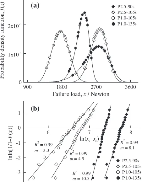
Fitting the failure load data into eq. (1), the failure
probability density function fðxÞcurves of the FSSW
5052-R lap-joints are plotted in Fig. 3(a). The cumulative failure
probability FðxiÞ was estimated using the Benard’s median
rank of eq. (2).22)It is a very close approximated solution of a
statistical function,22,23)wherenis the total number of tested
samples andiis the sample rank in ascending order of failure
load. In addition, the joining reliability functionRðxiÞwith a
relation of RðxiÞ ¼1FðxiÞ is defined as the survival
probability19) of lap-joints for the purpose of following
discussion. Figure 3(b) shows the double natural logarithmic (ln) graphs (Weibull distribution plots) for the cumulative
failure probability at each corresponding failure load xi
(i¼1{20), so as to graphically evaluate the Weibull
modulus from the slope of a least-squares fitting method of
eq. (3) at a maximum coefficient of determination (R2). As
can be seen in Fig. 3(b), a good linear relationship is observed, suggesting that the experimental data can be reasonably described by the Weibull model. The results of Weibull statistical analysis are listed in Table 1, and the detail of Weibull statistics on the failures and the mechanical properties of the FSSW lap-joints will be discussed in the next paragraph.
FðxiÞ ¼
i0:3
nþ0:4 ð2Þ
ln ln 1
1FðxiÞ
¼mlnðxixoÞ mlnxc ð3Þ
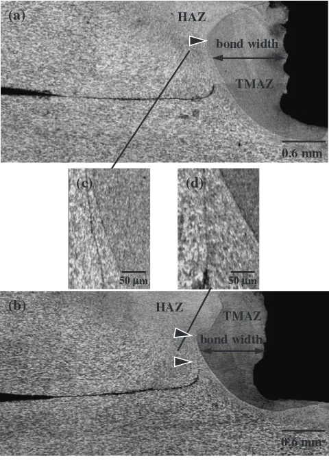
3.2 Joining microstructures of the FSSW lap-joints Figure 4 shows the cross-sectional features of the FSSW P2.5-90s and P2.5-105s lap-joined specimens with the heat affected zone (HAZ) and thermo-mechanically affected zone (TMAZ) created around the probe. With the severe plastic deformation during FSSW process, evident plastic metal flow is observed close to the HAZ and fine grains are formed within TMAZ. The average grain size within TMAZ for
P2.5-90s and P2.5-105s is about 3:80:2mm and 3:9
0:4mm, respectively. This effect should be resulted from the
dynamic recrystallization at the stir zone during the friction
stirring process.24) In the present study, the bond width of
P2.5-series lap-joints (as shown in Fig. 4(a) and (b)) is recognized as a region of grain refining with fully
metal-lurgical bond according to the definition of previous study,13)
but the obvious lap-sheets interface represents that there is almost no contact away from the bond region. Besides, an apparent microcrack is observed close to the HAZ/TMAZ interface as shown in Fig. 4(c) and (d), which are denoted by triangle arrows in Fig. 4(a) and (b), respectively. This area
900 0 1x10⁻³ 2x10⁻³
Probability density function,
f
(
x
)
Failure load, x / Newton
(a)
P2.5-90sP2.5-105s P1.0-105s P1.0-135s
6
-3 -2 -1 0 1
lnln[1/1
−
F
(
xi
)]
ln(xi−xo)
(b)
P2.5-90s P2.5-105s P1.0-105s P1.0-135s
R2 = 0.99
m = 8.1
R2 = 0.99
m = 10.5
R2 = 0.99
m = 4.5
R2 = 0.99
m = 3.3
3600 2700
1800
8 7
[image:3.595.57.283.76.366.2]Fig. 3 (a) The failure probability density functionfðxÞcurves, and (b) the Weibull distribution plots of various FSSW-joined specimens.FðxiÞis the cumulative failure probability at the corresponding failure load (xi) and the slope represents the Weibull modulus (m).
Table 1 Results of the failure load measurements for FSSW 5052 aluminum alloy lap-joints with various joining conditions.
Failure load,
x(kN)
Minimum failure load,
xo(kN)
Characteristics failure load,xc(kN)
Weibull modulus,
m
P2.5-90s 2.671 0.416 2.812 8.1
P2.5-105s 2.761 1.927 2.858 4.5
P1.0-105s 1.765 1.121 1.855 3.3
P1.0-135s 2.325 0.796 2.399 10.5
Each value was the average of twenty tests (n¼20). Data were calculated fromln lnð1=1Fðx
[image:3.595.47.551.692.766.2]may become the crack propagation path as the failure occurred during the tensile shear tests.
Figure 5(a) and (b) show the cross-sectional features of P1.0-105s and P1.0-135s conditions, which are different from P2.5-series lap-joints. For the P1.0-105s lap-joints (Fig. 5(a)), the bonded area can be recognized just under-neath the probe, and the mechanical kissing bond is observed as shown in the high magnification image of Fig. 5(c). Compared with the 105s lap-joints, however, the P1.0-135s lap-joints display a different microstructural feature, which represents a darkling TMAZ region with an indistinct HAZ/TMAZ interface. The metallurgical bonded region can be recognized at the TMAZ region also created around the probe. The presence of TMAZ region for the P1.0-135s lap-joints should be resulted from a longer welding dwell time, which provides enough friction heat to induce the metal plastic flow and the dynamic recrystallization during FSSW process. The average grain size within the TMAZ region of
P1.0-135s lap-joints is about 4:00:3mm. Away from the
TMAZ, the kissing bond is formed as shown in Fig. 5(b) and the high magnification image of Fig. 5(d). In addition, the metal plastic flow occurred under this welded condition is also distinctly observed from the concave curvature of kissing bonded line. Since the variability of failure load should probably be affected with the microstructural features for different welding conditions, the results of the Weibull
statistical analysis of variance made it possible to assess the role of the microstructure in determining the failure behavior of FSSW lap-joints.
3.3 Microstructural variations affect the failure load data fluctuation and failure behaviors
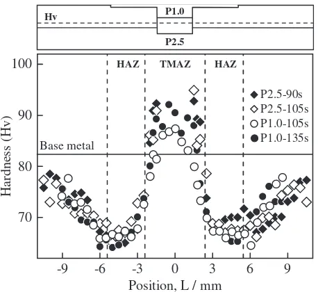
Figure 6 displays the microhardness (Hv) profiles along the cross-sections of various FSSW-joined specimens. The dash line represents the Vickers indenter testing area, which is located above the lap-sheets interface. The results represents that the variability of microhardness generally displays a W-type data distribution throughout the cross-sections for these joining conditions. The microhardness within TMAZ region is increased and significantly higher than the average level of the base-metal. This phenomenon can be resulted from the grain refining effect within the TMAZ region as shown in Figs. 4 and 5(b). But the obviously lower microhardness at the TMAZ region of P1.0-105s lap-joints can be recognized as slight metallurgical bond within TMAZ than the other conditions. However, the microhard-ness decreased markedly at the HAZ region, which is a soften region and shows the lowest microhardness within the cross-sections of lap-joined specimens.
Considering the above-mentioned microstructural exami-nations, a fairly amount of data fluctuation for these specimens shown in Fig. 2 can be probably recognized as a result of the significant differences of microhardness and the microstructural inhomogeneity with various probe penetra-tion depth and welding dwell time. Because the Weibull
(c)
50 mµµ
bond width
(a)
TMAZ HAZ
0.6 mm
(d)
HAZ
TMAZ
(b)
bond width
0.6 mm
50 mµ
Fig. 4 The cross-sectional feature of FSSW lap-joints for (a) P2.5-90s, (b) P2.5-105s conditions (TMAZ: thermo-mechanical affected zone, HAZ: heat affected zone). The HAZ/TMAZ interface of P2.5-90s and P2.5-105s conditions are shown in images (c) and (d), respectively.
(b)
TMAZ
metallurgical bond
kissing bond
0.4 mm
(c)
100µm
(d)
100 µm
kissing bond
(a)
0.4 mm
[image:4.595.308.548.72.379.2] [image:4.595.49.289.73.409.2]distribution function has been adopted to model the reliability
and the failure mechanism of materials,25–27) a failure rate
functionðxiÞshown in eq. (4) at each corresponding failure
load is further defined for the assessment of failure behaviors.
Figure 7(a) and (b) show the failure rate function ðxÞand
reliability functionRðxÞ curves of FSSW lap-joints,
respec-tively.
ðxiÞ ¼
fðxiÞ
RðxiÞ
¼ m xcm
ðxixoÞm1 ð4Þ
Referring to the analysis results listed Table 1, the examination of the Weibull modulus (m) and failure rate function represent that FSSW-joined 5052 aluminum alloys are reliable lap-joints with a right-shift wear-out failure
model (m>3) of increasing failure rate (IFR).22,28,29)
Furthermore, P2.5-90s and P1.0-135s FSSW lap-joints with a larger Weibull modulus is recognized as the failure occurred in a relatively concentrated data distribution range (Fig. 7(a)) and less reliability decrease (Fig. 7(b)) while the loading exceeds the minimum strength. Meanwhile, knowl-edge of the Weibull modulus can be used to determine which
material has higher reliability.30)Since the Weibull modulus
is a measure of the variability of material mechanical
properties,31) two or more materials with similar values of
mechanical properties (i.e., an average value or the extent of data fluctuation) may be differentiated and compared through their respective Weibull modulus. Giving the same welding dwell time for the probe penetration depth of 2.5 mm and 1.0 mm, the P2.5-105s lap-joints not only resist a higher extent of failure load but also show more reliable than the P1.0-105s lap-joints because it has a larger Weibull modulus. According to this analysis, the FSSW lap-joints with a metallurgical bonded TMAZ region (Fig. 4(b)) show a better joining reliability than just kissing bonded (Fig. 5(a)) for the short probe penetration depth.
However, it should be noted that a larger value of Weibull modulus does not necessarily imply a higher mechanical property. The Weibull modulus is a dimensionless parameter,
which indicates the degree of the uniformity of a mechanical property throughout the specimen, not its absolute value. For example, the average failure load of P2.5-90s lap-joints is larger than P1.0-135s lap-joined specimens, whereas the P2.5-90s lap-joints show a smaller Weibull modulus. In addition, the significant variation in the Weibull modulus for
P2.5-90s (m¼8:1) and P2.5-105s (m¼4:5) lap-joined
specimens, which display a similar failure load data fluctua-tion, can reflect the difference in the failure behaviors. Although both of P2.5-90s and P2.5-105s lap-joints show similar FSSW-joined microstructural feature with metal-lurgical bonded TMAZ region and microhardness, but the cracks between the HAZ/TMAZ interface indicated by triangle arrows in Fig. 4(b) and (d) for the P2.5-105s condition are extended to approach the lap-sheets interface compared with the P2.5-90s condition. This phenomenon makes cracks further propagate along this defect when the failure occurred during the tensile shear loading. Therefore, longer welding dwell time is not available for the FSSW process with a probe penetration depth passes the lap-sheets interface. For the P1.0-series conditions, a large Weibull
modulus for P1.0-135s lap-joints (m¼10:5) corresponds to a
metallurgical bonded microstructure with a uniform failure load, whereas just a kissing bonded microstructure with a broad distribution of failure load is associated with a relatively low Weibull modulus for the P1.0-105s lap-joints
(m¼3:3). The reason can be recognized as the metallurgical
bonded TMAZ region formed with plastic flow for the longer -9
70 80 90 100
P2.5-90s P2.5-105s P1.0-105s P1.0-135s
Hardness (Hv)
Position, L / mm Base metal
TMAZ HAZ
HAZ Hv
P2.5 P1.0
9 6 3 0 -3 -6
Fig. 6 Microhardness (Hv) of various FSSW lap-joints. The indentations were made with a spacing of 0.25 mm along the parallel dash line.
(a)
P2.5-90s P2.5-105s P1.0-105s P1.0-135s
900 0 1x10⁻² 2x10⁻²
Failure rate,
(
x
)
Failure load, x / Newton
900 0.0 0.5 1.0
Reliability,
R
(
x
)
Failure load, x / Newton
P2.5-90s P2.5-105s P1.0-105s P1.0-135s
(b)
0.632
3600 2700
1800
3600 2700
1800
Fig. 7 (a) Failure rate functionðxÞcurves, and (b) reliability functionRðxÞ
[image:5.595.56.285.70.280.2] [image:5.595.314.541.74.399.2]welding dwell time of the P1.0-135s (Fig. 5(b)) than the P1.0-105s.
Properly welded joints should have high failure load, display ductility and failed by tear-out of a large section of
the joined interface,13)whereas poorly welded joints with low
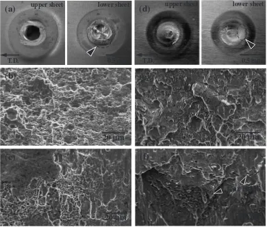
failure load will fail in a brittle manner at the welding region. To distinct the fracture modes observed from the tensile shear testing of FSSW lap-joined specimens, Fig. 8 shows the failure morphologies and SEM fracture surfaces of these FSSW lap-joints. Figure 8(a) represents typical failure morphology for the P2.5-serious FSSW lap-joints, which generally display a hole at the upper sheet and a fracture ring observed at the TMAZ around the probe hole after tensile shear tests. Figure 8(b) and (c) show the SEM fracture surfaces taken from circled area indicated by the arrow in Fig. 8(a). Both P2.5-90s and P2.5-105s lap-joints exhibit ductile failure morphologies with dimples fracture, but a partial fracture surface of the P2.5 105s lap-joints (Fig. 8(c)) shows a flat, brittle-like failure area. This phenomenon may be an instable cause for the decrease of the Weibull modulus. Figure 8(d) shows the general failure morphology for the P1.0-serious FSSW lap-joints without any probe hole at the upper sheet. The failure morphologies of P1.0-series FSSW lap-joints are quite different from the P2.5-series. Figure 8(e) shows a brittle fracture for the P1.0-105s lap-joints, which have relatively lower failure load than other conditions. It should be resulted from the non-metallurgical kissing bond as
displayed in Fig. 5(a) and (c). However, the fracture surface of P1.0-135s lap-joints as shown in Fig. 8(f) displays a microstructural feature of the ductile failure with obvious tear ridges. Based on the above observations, it is recognized that the ductile fracture of FSSW lap-joints is generally occurred with increasing the tensile shear failure load.
4. Conclusions
The microstructural features, tensile shear failure load and failure mechanism with Weibull statistical analysis for the FSSW lap-joints of 5052-H34 aluminum alloy have been characterized. The results can be summarized as follows:
(1) The TMAZ region with a metallurgical bond is created around the probe, and the microhardness is significantly increased at the TMAZ region for FSSW-joined 5052 aluminum alloys. But the microhardness is sharply decreased within the HAZ region.
(2) A higher failure load is obtained for the FSSW lap-joints with an obvious metallurgical bonded TMAZ region. Besides, the failure load as well as the Weibull modulus is decreased with decreasing the probe penetration depth.
(3) The failure load and the Weibull modulus are signifi-cantly increased with performing a longer welding dwell time for the FSSW lap-joints welded with a short probe penetration depth.
(d)
upper sheet0.5 mm T.D.
(a)
upper sheet0.5 mm T.D.
(e)
20
µ
m
(c)
20
µ
m
tear ridge
(f)
20
µ
m
(b)
20
µ
m
lower sheet lower sheet
[image:6.595.103.493.73.405.2](4) Through the powerful statistical analysis of the Weibull model, FSSW-joined 5052 rolled aluminum alloys with
a right-shift wear-out model (m>3) can be recognized
as reliable lap-joints for further engineering application. (5) A larger value of the Weibull modulus should not necessarily imply a higher failure load or a similar data fluctuation range. It represents the degree of the uniformity of a failure pertaining to the microstructural features throughout the material.
Acknowledgments
This study was financially supported by the National Science Council of Taiwan (Contract No. NSC 96-2628-E-006-008-MY3) for which we are grateful.
REFERENCES
1) S. Fukumoto, I. Lum, E. Biro, D. R. Boomer and Y. Zhou: Weld. J.82
(2003) 307s–312s.
2) P. Thornton, A. Krause and R. Davies: Weld. J.75(1996) 101s–108s. 3) A. Gean, S. A. Westgate, J. C. Kucza and J. C. Ehrstorm: Weld. J.78
(1999) 80s–86s.
4) W. M. Thomas, E. D. Nicholas, J. C. Needham, M. G. Murch, P. Templesmith and C. J. Dawes: GB Patent Application No. 9125978.8, December 1991.
5) Y. S. Sato and H. Kokawa: Metall. Mater. Trans. A32A(2001) 3023– 3031.
6) S. Lathabai, M. J. Painter, G. M. D. Cantin and V. K. Tyagi: Scr. Mater.
55(2006) 899–902.
7) Y. C. Chen and K. Nakata: Scr. Mater.58(2008) 433–436.
8) P. C. Lin, S. H. Lin, J. Pan, T. Pan, J. M. Nicholson and M. A. Garman: SAE Technical Paper No. 2004-01-1330, (Society of Automotive Engineering, Warrendale, PA, 2004).
9) R. Hancock: Weld. J.83(2004) 40.
10) K. T. Huang, T. S. Lui and L. H. Chen: Mater. Trans.45(2004) 3216– 3222.
11) Y. S. Sato, H. Kokawa, K. Ikeda, M. Enomoto, S. Jogan and T. Hashimoto: Metall. Mater. Trans. A32A(2001) 941–948.
12) Y. Hovanski, M. L. Santella and G. J. Grant: Scr. Mater.57(2007) 873–876.
13) D. Mitlin, V. Radmilovic, T. Pan, J. Chen, Z. Feng and M. L. Santella: Mater. Sci. Eng. A441(2006) 79–96.
14) A. Gerlich, M. Yamamoto and T. H. North: Sci. Technol. Weld. Joining
13(2008) 254–264.
15) W. Weibull: J. Appl. Mech.18(1951) 293–297.
16) R. Tsujino, K. Morikawa, Y. Ohue, H. Yamaguchi, K. Ogawa and H. Ochi: J. Jpn. Inst. Light Met.50(2000) 281–286.
17) L. Esposito, A. Tucci and D. Naldi: J. Eur. Ceram. Soc.25(2005) 1487–1498.
18) Y. Y. Zhao, E. Ma and J. Xu: Scr. Mater.58(2008) 496–499. 19) C. W. Yang and T. S. Lui: J. Eur. Ceram. Soc.28(2008) 2151–2159. 20) S. S. Scherrer, I. L. Denry, H. W. Anselm Wiskott and U. C. Belser:
Dent. Mater.17(2001) 367–371.
21) R. T. Kiepura and B. R. Sanders (Eds.):Metals Handbook Volume 9, Metallography and Microstructures, ninth ed., (American Society for Metals, Metals Park, Ohio, 1985) pp. 352–354.
22) R. B. Abernethy: The New Weibull Handbook: Reliability and Statistical Analysis for Predicting Life, Safety, Survivability, Risk, Cost and Warranty Claims, 4th Ed. (North Palm Beach, FL, 2000). 23) B. Faucher and W. R. Tyson: J Mater. Sci. Lett.7(1988) 1199–1203. 24) S. Y. Chang, J. G. Lee, K. T. Park and D. H. Shin: Mater. Trans.42
(2001) 1074–1080.
25) K. Morikawa, Y. Ohue, K. Oquwa and H. Nakayama: Proc. Int. Offshore and Polar Engineering Conf.4(2000) 145–149.
26) N. Biery, M. de Greaf, J. Beuth, R. Raban, A. Elliott, C. Austin and T. M. Pollock: Metall. Mater. Trans. A33(2002) 3127–3136. 27) M. Sivapraqash, P. R. Lakshminarayanan, R. Karthikeyan, K.
Raqhukandan and M. Hanumantha: Mater. Design29(2008) 1549– 1553.
28) R. S. Lima and B. R. Marple: J. Therm. Spray Technol.12(2003) 240–249.
29) T. E. Wondmaqeqnehu: Nav. Res. Log.51(2004) 491–500. 30) R. S. Lima and B. R. Marple: J. Therm. Spray Technol.12(2003)
360–369.