Clearance Compensation Effect in Fine Precision Shearing
*1Masahiro Sasada, Naoki Koura
*2and Isamu Aoki
Department of Mechanical Engineering, Kanagawa University, Yokohama 221-8686, Japan
In this paper, we discuss the clearance compensation effect in precision shearing. This effect is based on the hypothesis that unbalanced clearance is automatically compensated by the bending of a punch when shearing is performed using a long and thin punch. We also discuss the compensation mechanism through various experiments and an elastic-plastic finite element method. When the clearances on the right and left sides differ, the shearing and horizontal forces acting on both punch sides also differ slightly. These forces result in moments that bend the punch. The clearance compensation effect depends on the magnitude and direction of these moments. In other words, the effect is due to not only the horizontal force but also the shearing force. In most cases of double-sided shearing, the existence of the compensation effect was apparent. [doi:10.2320/matertrans.P-MRA2007884]
(Received March 30, 2007; Accepted October 27, 2007; Published January 25, 2008)
Keywords: shearing, tool, punch deformation, elastic-plastic finite element method, clearance compensation, shearing force
1. Introduction
In recent years, demands for high precision at levels of several microns or above have grown stronger for products fabricated by shearing in many areas, and foils of several ten microns are also now commonly used as material. The clearance compensation effect has been considered as a means of realizing high-precision shearing. This effect is thought to be due to the presence of a mechanism that compensates for the difference in clearance between the left and right sides.1)To date, Takahashi and Aoki have studied this compensation mechanism through experiments2) and clarified that this effect mainly depends on the horizontal force and that the influences of shearing conditions, such as the constraint of the material, are strong.3)
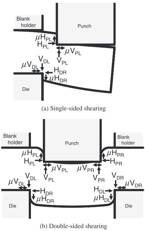
Single-sided shearing and double-sided shearing are typi-cal shearing methods. In this case, the various forces shown in Fig. 1 act on the punch. By considering the vertical forces acting on the top face to beVPL andVPR, and the horizontal
forces acting on the side of the punch to beHPLandHPR, the
respective friction forces will be VPL, VPR, HPL, and
HPR Here, L and R indicate the left and right sides,
respectively. Although these forces are distributed loads, they are converted to concentrated loads for simplification. In previous studies, it was demonstrated that punch deflection mainly depends on the horizontal force difference H (H¼ ðHPLþVPLÞ ðHPRþVPRÞ).3) However, if the
punch is long and thin, making it easy to deform, the influences of the left and right shearing forces (left shearing force =VPLþHPL, right shearing force =VPRþHPR)
are thought to increase. To use the clearance compensation effect effectively for actual shearing, the force components contributing to the compensation effect must be investigated and the true nature of the compensation mechanism, such as shearing conditions, and how these conditions should be treated, must be clarified.
FEM analysis is thought to be useful for this purpose, because this method allows a detailed study of the influences
of force components that are difficult to analyze by experi-ment, and important and beneficial findings on shearing have been obtained by FEM analysis.4–8)
In this paper, we discuss experiments and FEM analysis under specific conditions as the first step in clarifying the compensation mechanism and investigate the clearance compensation effect of unbalanced clearance due to punch deflection.
Die
V
PLµ
V
PLµ
H
PLH
PLµ
H
DRH
DRV
DLµ
V
DLPunch
Blank holder
Die
(a) Single-sided shearing
DL
V
PLµ
V
PLµ
V
PRV
PRµ
H
PLµ
H
PRH
PRH
PLµ
H
DRH
DRµ
H
DLH
DLV
DLV
DRµ
V
DRµ
V
Punch
Blank holder
Blank holder
Die Die
(b) Double-sided shearing
Fig. 1 Forces acting on tool cutting edge. (a) Single-sided shearing (b) Double-sided shearing.
*1This Paper was Originally Published in Japanese in J. JSTP47(2006) 968–972.
*2Graduate Student, Kanagawa University
[image:1.595.310.542.280.648.2]2. Experimental Method and Finite Element Analysis
2.1 Experimental methods
This study was conducted on single-sided shearing and double-sided shearing. Experiments were performed using the double-sided shearing equipment shown in Fig. 2, which can be also used for single-sided shearing. The punch was 1.2 mm thick, 8.5 mm wide and 15 mm long. The shape of the die was not changed, and clearances were adjusted to CL15%CR15%,CL10%CR20%andCL5%CR25%with
clear-ance adjusting blocks. Here,CLandCRare expressed as the
ratios of clearance to specimen thickness in percentage, and the indices L and R denote the left and right sides respectively. The punch and die were made of SKD11(JIS standard) with a hardness of 60HRC. The specimen was aluminum with a length of 30 mm, a width of 8 mm, and a thickness of 0.5 mm (JIS standard: A1100P-O). The blank holder was of the spring type and the blank holding forces (Fh) at the start of shearing was set at 41, 160, and 216N. The
lubricant used was a paraffin-type base oil (90106m2/s),
which was applied to the surface of the specimen before starting the experiment. The shearing speed was set at 50
mm/s.
The deflection of the punch was obtained by the method proposed by Takahashi and Aoki using a strain gauge output (hereafter called the gauge method).2) In this method, the
output from a strain gauge mounted onto the deformed punch is considered a boundary condition, and the deflection was calculated using the following eq. (1) between the deflection y and the moment M at the mounted position x. E is the Young’s modulus of the beam (punch) andIis the moment of inertia of area.
d2y dx2 ¼
M
EI: ð1Þ
In the gauge method, because surface strains are required at four locations on the punch, as shown in Fig. 3, four strain gauges are mounted at the positionsx1 ¼6 andx2¼9mm.
By this method, the punch deflection, shear force, and horizontal force difference were calculated.
2.2 FEM analysis
Using the finite element analysis software Marc2005, elastic-plastic analysis was performed. This analysis was carried out from the initial stage of shearing to the point before cracks occurred. In this analysis, material deformation was considered a plane strain state. Figure 4 shows an outline of the areas near the cutting edge of the analyzed model. The elements in ABCD (hereafter called the remeshed area) were remeshed during calculation. Remeshing was carried out when one of the following conditions was met.
(1) The punch stroke increased by 3mm.
(2) The overlap of the element between the punch and the work material reached 0.5mm.
Regarding the cutting edge roundness and number of elements of the remeshed area, the influence on the analysis results was studied as follows. In shearing with equal clearances on the left and right sides, although the horizontal displacement of the punch cutting edge should always be zero, a difference due to miscalculation error was observed. In this study, when this difference was less than 0.1mm, the analysis results were considered reliable. Eventually, the punch and die cutting edge roundnessRwas set at 20mmand the number of remeshed area elements of the specimen was
Displacement
sensor
Clearance
adjusting block
Blank
holder
Die
Punch
Specimen
Fig. 2 Main part of shearing tool.
Blank holder
Specimen
Die
x
1
x
2
Strain gauge
Punch
b
t
l
Fig. 3 Positions of mounted strain gages.
A
B C
D
Punch
Blank holder
Die
Specimen
CL CR
R R
R R
2.5
0.5
[image:2.595.53.278.74.284.2] [image:2.595.313.536.75.314.2] [image:2.595.321.533.352.468.2]set at about 60,000. Four-node quadrilateral elements were used, and the length of one side of the element near the cutting edge was about 4mm. The cutting edge R was confirmed to be more or less the same as the value measured at 10 to 15mm.
The following shows the characteristics of the specimen in the plastic region obtained from tensile tests.
¼33þ142 ""p0:37 ðMPaÞ ð2Þ
The characteristics of the specimen in the elastic region were a Young’s modulus of 69 GPa and a Poisson ratio of 0.33. The punch was an elastic body with a Young’s modulus of 210 GPa and a Poisson ratio of 0.3. The blank holder and die were assumed to be rigid bodies. The friction was Coulomb friction with a coefficient of¼0:1.
3. Experiments and Analysis Results
3.1 Calibration of gauge method
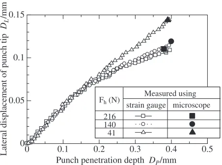
To verify the accuracy of punch deflection by the gauge method, the calculated results from the strain gauge output in single-sided shearing were compared with the results of image measurement using a CCD microscope. Figure 5 shows these results. The results obtained from the strain gauge output and the lateral displacement of the punch obtained from images were almost same. The lateral displacement calculated from the strain gauge output was confirmed to be sufficiently accurate. The punch lateral displacement obtained by the gauge method was then studied as an experimental result.
3.2 Single-Sided Shearing
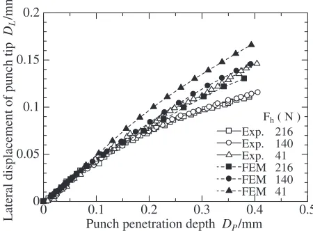
Figure 6 shows a comparison of the material deformations obtained analytically and experimentally during shearing when the clearance is 0%. Figure 7 shows the diagrams of shearing force and horizontal force difference. In whichever case, the analytical and experimental results agreed. This tendency for the shearing force to increase and the horizontal force difference to decrease with an increase in blank holding force is already known. Figure 8 shows an example of the bended shape of the punch. Figure 9 shows the variation in
the lateral displacement of the punch tip with punch penetration depth. In both figures, the direction in which the punch deflects from the die is positive and the reverse direction is negative. In both cases, the analytical and experimental results agreed well.
[image:3.595.57.283.71.239.2]3.3 Double-Sided Shearing
Figure 10 shows a comparison of the material deforma-tions obtained analytically and experimentally during shear-ing. The difference in material deformation due to the unbalance between the left and right clearances can be observed clearly. The analytical and experimental results agreed well.
Figure 11 shows the diagrams of shearing force and horizontal force difference. The horizontal force difference is more or less zero in a balanced clearance. In the case of an unbalanced clearance, after the horizontal force difference works in the compensation direction, it decreases with the progress of shearing and becomes negative. Here, the
0 0.1 0.2 0.3 0.4 0.5
0 0.05 0.1 0.15
Punch penetration depth DP/mm
Lateral displacement of punch tip
DL
/mm
Measured using Fh (N) strain gauge microscope
216 140 41
Fig. 5 Comparison of lateral displacements of punch tips measured using strain gage and microscope (single-sided shearing, clearance: 0%).
0.1mm
0.1mm
(a) Experimental result
(b) FEM result
[image:3.595.313.539.79.416.2] [image:3.595.311.539.223.494.2]negative horizontal force difference means the formation of the bending moment of the punch in the noncompensation direction.
Figure 12 shows an example of the bended shape of the punch as shearing progresses in the case of CL5%CR25%.
Figure 13 shows the variation in the lateral displacement of
the punch tip under three clearance conditions. In both figures, the value of the punch deflection is positive when punch deflection compensates for the unbalanced clearance. The experimental and analytical results for deflection agreed well. In the case of a balanced clearance, there is more or less no punch deflection. On the other hand, in the case of an unbalanced clearance, the punch bends in the compensation direction for both experimental and analytical results. The greater the clearance unbalance, the greater the amount of compensation.
By comparing Fig. 11(b), which shows the horizontal force difference, with Fig. 13, which shows the lateral displacement of the punch tip, even in the area where the
0 0.1 0.2 0.3 0.4 0.5
0 50 100 150 200 250
Punch penetration depth DP/mm
Shearing force
V
/N
Exp. Exp. Exp. FEM FEM FEM
Fh (N)
(a)Shearing force
0 0.1 0.2 0.3 0.4 0.5
0 10 20 30 40 50
Punch penetration depth DP/mm
Horizontal force dif
ference
H
/N
∆
Exp. Exp. Exp. FEM FEM FEM
Fh ( N )
(b)Horizontal force difference
216 140 41 216 140 41
216 140 41 216 140 41
Fig. 7 Diagrams of shearing force and horizontal force difference (single-sided shearing, clearance: 0%). (a) Shearing force (b) Horizontal force difference.
0 0.02 0.04 0.06 0.08 0.1 0.12 0.14
0 5 10 15
Lateral displacement of punch DL/mm
Distance from punch tip
L
/mm Exp.
Exp. Exp. FEM FEM FEM
Punch penetration depth (mm)
0.01 0.1 0.3 0.01 0.1 0.3
Fig. 8 Illustration of bending of punch in single-sided shearing (Fh: 216N, clearance: 0%).
0 0.1 0.2 0.3 0.4 0.5
0 0.05 0.1 0.15 0.2
Punch penetration depth DP/mm
Lateral displacement of punch tip
DL
/mm
Exp. Exp. Exp. FEM FEM FEM
Fh ( N )
216 140 41 216 140 41
Fig. 9 Variation in lateral displacement of punch tip with punch penetration depth (clearance: 0%).
0.5mm
(a) Experimental result
[image:4.595.57.282.75.436.2](b) FEM result
[image:4.595.313.538.77.243.2] [image:4.595.312.540.294.569.2] [image:4.595.55.281.498.663.2]horizontal force difference decreases, the punch is observed to bend in the compensation direction, demonstrating that the compensation effect cannot be explained simply by the horizontal force difference.
3.4 Compensation mechanism
In this section, the compensation mechanism is discussed
on the basis of the above-mentioned results.
Because the horizontal and shearing forces do not act on the punch individually, punch deflection cannot be obtained by combining the deflections obtained from the respective forces. In this case, because the punch deflection is minute, the deflection was calculated using eq. (1) from the various forces obtained by FEM analysis. By assuming that the moment obtained from the horizontal force difference isMH
and the moment obtained from the shearing force isMV, the
deflection of the punch tip when these moments act on the punch was calculated. In this case, the moment obtained from the shearing force is considered to be a fixed moment. The sum of the deflections from the respective forces is also calculated to confirm the difference caused by the combina-tion of the forces. Figure 14 shows the state of the punch schematically.
3.4.1 Single-sided Shearing
Figure 15 shows the deflection of the punch tip when the moments MH and MV are assumed. For a comparison, the
0 0.1 0.2 0.3 0.4 0.5
0 100 200 300 400 500 600
Exp. CL15%CR15% Exp. CL10%CR20%
Exp. CL 5%CR25% FEM CL15%CR15%
FEM CL10%CR20% FEM CL 5%CR25%
Punch penetration depth DP/mm
Shearing force
V
/N
(a)Shearing force
0 0.1 0.2 0.3 0.4 0.5
-3 -2 -1 0 1 2 3
Exp. CL15%CR15%
Exp. CL10%CR20%
Exp. CL5%CR25%
FEM CL5%CR25%
FEM CL15%CR15%
FEM CL10%CR20%
Horizontal force dif
ference
H
/N
∆
[image:5.595.58.282.74.431.2]Punch penetration depth DP/mm (b)Horizontal force difference
Fig. 11 Diagrams of shearing force and horizontal force difference (double-sided shearing, Fh: 216N). (a) Shearing force (b) Horizontal force difference.
0 2 4 6 8
0 5 10 15
Lateral displacement of punch DL/µm
Distance from punch tip
L
/mm
Exp. Exp. Exp. FEM FEM FEM Punch penetration depth (mm)
0.3 0.1 0.01 0.3 0.1 0.01
Fig. 12 Illustration of bending of punch in double-sided shearing (CL5%CR25%,Fh: 216N).
0 0.1 0.2 0.3 0.4 0.5
-2 0 2 4 6 8
Lateral displacement of punch tip
DL
/
µ
m
Punch penetration depth DP/mm Exp. CL15% CR15%
Exp. CL10% CR20% Exp. CL5% CR25%
FEM CL15% CR15%
[image:5.595.313.539.76.245.2]FEM CL10% CR20% FEM CL5% CR25%
Fig. 13 Variation in lateral displacement of punch tip with punch penetration depth (Fh: 216N).
HPR
Punch
VPL
HPR
HPL
VPR
M
HLM
HRM
VLM
VRVPL VPR
µ
µ
µ
µ
HPL
[image:5.595.313.539.298.512.2]M
H=M
HL+M
HR, M
V=M
VL+M
VR [image:5.595.56.283.488.655.2]analytical results of Fig. 9 are also shown in the figure. Owing toMH, the punch bends in the direction in which it
deflects from the die. On the other hand, MV acts in the
direction in which the deflection is suppressed. Given that the deflection resulting only from MH is greater than that
obtained by FEM analysis, the punch deflection cannot be determined only from the horizontal force, and the shearing force is also affected. In addition, with the increase in blank holding force, the punch deflection due toMVincreases in the
direction in which the deflection is suppressed, and that due toMHdecreases.
[image:6.595.55.280.71.243.2]3.4.2 Double-sided shearing
[image:6.595.314.539.77.444.2]Figure 16 shows the deflection of the punch tip calculated fromMHandMV. For a comparison, the analytical results of
Fig. 13 are also shown in the figure. With the progress of shearing, the direction of the punch deflection caused byMH
changes from the compensation direction to the noncompen-sation direction. On the other hand, that of the deflection caused byMVchanges from the noncompensation direction
to the compensation direction.
In this way, punch deflection cannot be explained simply by MH alone; however, it can be explained reasonably by
considering MV. This indicates that the moment caused by
the shearing force also contributes greatly to punch deflec-tion.
Figure 17 shows changes in the vertical forcesVPLandVPR
and the horizontal force difference obtained by FEM analysis performed to study the above-mentioned punch deflection from the viewpoint of the shearing phenomenon. The different shearing phenomena occur owing to the difference in clearance between the left and right sides. Generally, when the clearance is small, the shearing strain increases compared with that when the clearance is large, and the shearing and horizontal forces reach maximum values at an early stage.
In this study, the left-side vertical forceVPLis greater than
the right-side vertical forceVPRin the early stage of shearing,
and this reverses in the latter stage of shearing. Consequently, in the early stage, the moment MV works in the
non-compensation direction, and this reverses in the latter stage. On the other hand, the moment MH caused by the
horizontal force difference works in the compensation direction in the early stage of shearing and in the non-compensation direction in the latter stage. This can be explained as follows: Although the horizontal force in the early stage is greater on the left side than on the right side, as shearing progresses, the punch tends to bend so that the
0 0.1 0.2 0.3 0.4 0.5
-0.1 0 0.1 0.2 0.3
MH (Fh:216N)
MV (Fh:216N)
FEM (Fh:216N)
Punch penetration depth DP/mm
Lateral displacement of punch tip
DL
/mm
MH (Fh:41N)
MV (Fh:41N)
MH+MV (Fh:216N)
MH+MV (Fh:41N)
FEM (Fh:41N)
Fig. 15 Diagrams showing lateral displacement of punch tip consisting of two bending components due to shearing and horizontal forces (single-sided shearing).
0 0.1 0.2 0.3 0.4 0.5
-20 -10 0 10 20
Punch penetration depth DP/mm
Lateral displacement of punch tip
DL
/m
MH
MV
FEM MV+MH
(a)CL5%CR25%
0 0.1 0.2 0.3 0.4 0.5
-20 -10 0 10 20
Punch penetration depth DP/mm
Lateral displacement of punch tip
DL
/
µµ
m
MH
MV
MV+MH
FEM
(b)CL10%CR20%
Fig. 16 Diagrams showing lateral displacement of punch tip consisting of two bending components due to shearing and horizontal forces (double-sided shearing,Fh: 216N). (a)CL5%CR25%(b)CL10%CR20%.
0 0.1 0.2 0.3 0.4 0.5
0 50 100 150 200 250 300 350
-3 -2 -1 0 1 2 3
Punch penetration depth DP/mm
Shearing force
V
/N
Horizontal force dif
ference
H
/N
∆
VPR(CL5%CR25%)
VPL(CL5%CR25%)
VPR(CL10%CR20%)
VPL(CL10%CR20%)
H(CL5%CR25%)
H(CL10%CR20%)
∆
∆
[image:6.595.314.538.512.663.2]horizontal force difference approaches zero. The direction in which MV acts also changes from the noncompensation
direction to the compensation direction. As a result, the punch bends, causing the reaction force on the right side of the punch in contact with the workpiece to increase. In this way, the reaction force from the material on the right side of the punch increases in the latter stage of shearing, and as a result, the horizontal force difference becomes negative.
In this way, each component fluctuates with the progress of shearing. As shown in Fig. 16, the moment due to the horizontal force works in the compensation direction in the early stage of shearing and in the noncompensation direction in the latter stage of shearing. On the other hand, the moment due to the shearing force acts in the noncompensation direction in the early stage and in the compensation direction in the latter stage. The punch deflection is determined from these two moments. The greater the clearance difference between the left and right sides, the greater the left and right shearing force difference and horizontal force difference, and the greater the punch deflection.
4. Conclusion
In this study, the clearance compensation effects, which are expected to enhance the accuracy of fine precision shearing, were investigated. The following findings were obtained.
(1) If the left and right clearances differ, different shearing phenomena occur on the left and right sides, where clearance compensation is expected.
(2) Punch deflection is affected by not only horizontal force but also shearing force.
(3) When investigating the effects of shearing force on punch deflection, the left and right sides should be treated separately as in the case of horizontal force. (4) In single-sided shearing, horizontal force works in the
direction in which the punch deflects from the die, and shearing force works in the direction in which punch deflection is suppressed. When blank holding force increases, shearing force increases and horizontal force decreases, thus decreasing punch deflection.
Acknowledgement
This research was partly funded by Grant-In-Aid for Scientific Research (C) (No. 16560101) from JSPS.
REFERENCES
1) T. Maeda and S. Mekaru: J. JSTP18(1977) 329–336. 2) T. Takahashi and I. Aoki: J. JSTP36(1995) 155–160.
3) I. Aoki, T. Takahashi, H. Saito, A. Gotoh and K. Sakamoto: J. JSTP37
(1996) 1316–1321.
4) K. Komori: J. JSTP38(1997) 129–134.
5) N. Yukawa, Y. Inukai, Y. Yoshida, T. Ishikawa and T. Jimma: J. JSTP
39(1998) 1129–1133.
6) N. Hatanaka, F. Sekine and K. Yamaguchi: Trans. JSME, Series C67
(2001) 2352–2359.
7) A. M. Goijaerts, L. E. Govaert and F. P. T. Baaijens: J. Mater. Process. Technol.110(2001) 312–323.