Roles of Pre-Existing Hydrogen Micropores on Ductile Fracture
Hiroyuki Toda
1, Hideyuki Oogo
1;*, Kentaro Uesugi
2and Masakazu Kobayashi
11Department of Production Systems Engineering, Toyohashi University of Technology, Toyohashi 441-8580, Japan 2Japan Synchrotron Radiation Research Institute, Sayo-Gun, hyougo 679-5198, Japan
Synchrotron X-ray microtomography was used to observe hydrogen micropores. Competitive growth between pre-existing high-density micropores and voids originating from damage during loading was observed in an aluminum alloy during a tensile test. Extensive and premature growth of pre-existing hydrogen micropores has been observed during tension, while the ordinary damage initiation increased rapidly more later. According to the estimation on the areal fraction of dimple patterns originating from the pre-existing hydrogen micropores, it has been concluded that the hydrogen micropores more or less make contributions to ordinary ductile fracture. [doi:10.2320/matertrans.M2009123]
(Received April 7, 2009; Accepted June 10, 2009; Published July 23, 2009)
Keywords: porosity, tomography, synchrotron radiation, aluminum-copper alloy, ductile fracture, damage evolution
1. Introduction
It has been well documented that solid aluminum contains supersaturated hydrogen1)due to the existence of the
hydro-gen solubility gap at the melting temperature of aluminum.2)
Porosity is one of the common production defects observed in both wrought and cast aluminum alloys.1,3) It has been
clarified that percentage porosity depend on the hydrogen content in aluminum alloy,4,5) strongly suggesting that micropores in aluminum alloys are filled with molecular hydrogen. Synchrotron X-ray microtomography has been applied to the observations of high-density micropores,6–12) because this technique is especially effective for micropore observation, since micropores are easily filled with abrasive powders during sample preparation processes for observa-tion, such as cutting and polishing.
The mechanical properties of aluminum alloys are some-times sensitive to the presence of micropores.5)For example,
it has been reported that tensile strength decreases rapidly if porosity increases up to 0:51%.4) It seems that the
mechanisms for such rapid decrease with a limited porosity have not been fully clarified in the literature. Since the ordinary ductile fracture process consists of void initiation, growth and coalescence, it can be readily supposed that the high-density micropores make some contributions to ductile fracture. Actually, Kobayashiet al.have demonstrated strain localization around micropores that are aligned along grain boundary using an image-based numerical simulation tech-nique.13) In the Al-Si alloy with completely spherical Si
particles, it has been revealed that the simple growth of pre-existing micropores is mainly observed and the nucleation of new voids at silicon particles is quite rare.14)More detailed
analysis might be expected in order to understand actual ductile fracture process quantitatively.
It is the objective of the present study to investigate the behaviors of micropores during ductile fracture using state-of-the-art synchrotron X-ray microtomography. High-reso-lution 3-D/4-D (i.e., 3-D with a time axis) imaging and subsequent image analysis readily enable the visualization and tracking of each micropore until fracture, providing
unique possibilities for analyzing the contribution of micro-pores on ductile fracture in a quantitative manner.
2. Experimental Methods
2.1 Tomographic experiments
A rolled plate of a 2024-T3 aluminium alloy was tested in the L-T orientation. A small parallelepiped specimen shown in Fig. 1 was machined from the rolled plate in the rolling direction. The plate was solution heat-treated in advance for 7.2 ks at 768 K, and then quenched into ice water and naturally aged approximately for 2,300 ks at room temper-ature to provide a T3 temper condition.
[image:1.595.340.512.561.766.2]X-ray tomography was performed at the undulator beam-line BL47XU of the SPring-8 synchrotron radiation facility. A monochromatic X-ray beam with a photon energy of 20 keV was used for the observation. An image detector was positioned 20 mm behind the sample, making the imaging system sensitive to phase modulation in addition to the classical absorption contrast. The image detector consisted of a cooled 4000 (H)2624 (V) element CCD camera, which
[Unit:mm] 0.6
1.8
0.4
3
3.5
8 1.8
6 0.6
11
22
TAB
(R2)
Fig. 1 Geometry of the tensile test specimen.
*Graduate Student, Toyohashi University of Technology
was used in22binning mode, a scintillator (Lu2SiO5:Ce)
and a relay lens. In total, 1500 radiographs, scanning 180 degrees, were obtained around the loading axis in 0.12-degree increments for each load level. The other details are available elsewhere.10,12)
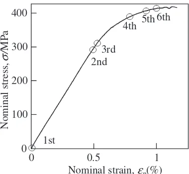
Theex-situtechniques were utilized to observe a specimen during monotonic tensile loading at room temperature. Loading rate was 0.013 mm/s. The first tomography scan was performed without loading and the subsequent six scans were performed including the observation of a fractured specimen. A stress-strain relationship is shown in Fig. 2.
Image slices were reconstructed from a series of projec-tions based on the conventional filtered backprojection algorithm. An isotropic voxel with a 0.506mm edge was achieved in the reconstructed slices.
2.2 Image analysis
Micropores were segmented and labeled in the tomo-graphic volumes. To estimate the volume of each micropore at sub-voxel accuracy, pentagonal facetted iso-intensity surfaces were computed from the volumetric data set using the conventional Marching Cubes algorithm. To suppress inaccuracies originating from image noise, only micropores over 23.168 voxels in volume were counted as micropores in the quantitative analysis. Volume, V, surface area, A, and gravity center are measured in the tomographic images. Equivalent diameter for sphere of equal volume and sphericity were defined as follows and used to evaluate micropores.
d
d¼2p3ffiffiffiffiffiffiffiffiffiffiffiffiffiffi3V=4
ð1Þ
Sp¼
ffiffiffiffiffiffiffiffiffiffiffiffiffiffiffiffiffiffiffi
36V2=A
3 p
ð2Þ
Micropores were tracked throughout deformation by employing the matching parameter method and local pattern matching that have been developed by the present authors.10) Since voids that originate from damage during loading appear after the onset of plastic deformation at the earliest, pre-existing hydrogen micropores can be classified from the voids by tracking pores from the unloading state to the final loading step. Micropores that can be tracked from the
unloading state are classified into hydrogen micropores and those appear from intermediate loading steps are assumed to be voids.
In addition, thus, the origins of dimple patterns on the fracture surface can be classified into the pre-existing micropores and damage at particles. Contributions of the pre-existing micropores and damage can be quantitatively evaluated by evaluating areal fractions on the fracture surface. To do this, particles observed in the tomographic image of a fracture surface were correlated with those before loading. By connecting particles in the initial image, a polygonal surface was reconstructed, which corresponded to a fracture path estimated in the image captured before loading. Considering average vertical depth of dimple patterns measured with a scanning electron microscope (10.05mm), the polygonal plane was shifted by 10mmbelow and above the estimated fracture surface. Micropores that have gravity centers within this region are assumed to create fracture surface. Then corresponding dimple patters were manually identified on the fracture surface with comparing tomographic slices.
3. Experimental Results
3.1 Microstructural features in the material used
Figure 3 shows the 3D distributions of micropores (shown in red) and particles (shown in green) before loading. A closer inspection revealed that the majority of micropores have been formed heterogeneously on constituent particles, which have been also confirmed more quantitatively for Al-Mg alloys in our recent paper.12) In the previous study, a
liquid gallium grain boundary wetting technique was applied to characterize a 3-D grain structure in a Al-4%Mg alloy.15)
It has been revealed that although some of micropores are located on grain boundaries, the majority of micropores are located in grain interior. Since void initiation during loading occurs either from particle fracture or interfacial debonding at particle/matrix interface, it might suggest that the pre-existing hydrogen micropores and voids caused by damage cannot be distinguished only with their morphology. There-fore the sophisticated tracking analysis should be applied to it.
The summary of the quantitative image analysis for microstructural features is shown in Table 1. Porosity for the present material was about 0.20%, which is smaller than reported porosity values of 0.25%6)and 0.49%12)for different
2024 aluminum alloys that have been supplied from different manufacturers. The porosity value is also relatively small for wrought aluminum alloys.12)The mean equivalent pore
diameter value of 4.3mmis also comparable with other 2024 aluminum alloys (7.2mmin6)and 4.0mmin12)).
3.2 Competition between hydrogen micropores and damage evolution
3D images captured before loading and at 6th loading step are shown in Fig. 4(a) and (b), respectively. Note that only micropores and particles are extracted, while underlying aluminum is not displayed in the figure. Blue circles in Fig. 4 indicate ordinary ductile fracture process that starts from the damage initiation at particles. Particle fracture at irregularly
0
100
200
300
400
Nominal stress,
σ
/
MPa
1st
0
Nominal strain,
ε
p(%)
2nd
6th
4th
3rd
5th
0.5
1
[image:2.595.75.265.70.245.2]shaped particles appears to be the major damage initiation event in the present material. On the other hand, red circles indicate the simple growth of pre-existing hydrogen micro-pores. It can be seen from Fig. 4 that the extent of growth seems to be different between hydrogen micropores and voids.
[image:3.595.321.530.74.234.2]It can be more clearly recognized with the results of tracking analysis shown in Fig. 5. Hydrogen micropores, which have been successfully tracked from the unloading state, started to grow from an early stage, while the ordinary damage initiation increased rapidly after plastic strain had been accumulated to some extent. Of the 7,143 hydrogen micropores observed in the first 3D image, 6,034 micropores could be tracked until the final loading step. The reason why the number of micropores tracked gradually decreased would
Table 1 Results of quantitative analysis for pores in the 2024 aluminum alloy used.
Number density,1012
p/m3 47.8
Volume fraction,Vf(%) 0.2
Average diamater,d/mm 4.3
Average sphericity,Sp/% 84.9
(a) Before loading
Particle Pore
(b) 6th loading step
Loading direction
100 µm
116
µ
m
Growth
Growth
Damage
Damage
100
µm
Fig. 4 3D perspective views of particles, pores and voids extracted from the tomographic volumes, representing micro-pore growth and void nucleation/growth in the material.
Pore
Particle
y
100
µ
m
x
z
100
µ
m
100
µ
m
Fig. 3 3D perspective view of micro-pore, void and particle distributions in the 2024 aluminum alloy used. The image was taken at the 1st step.
Mean diamater,
d
/
µ
m
5
7000 6000 5000 4000 3000 2000 1000 0 4
3.5
3 4.5
Count,
n
0 0.5 1 Nominal strain, εp(%)
Count
Count
Tracked pore
Tracked pore
(Micropores)
(Micropores)
Mean diamater
Mean diamater
Mean diamater
Mean diamater
Count
Count
Remaining pore
Remaining pore
(Mostly voids)
(Mostly voids)
[image:3.595.65.278.75.307.2] [image:3.595.47.291.396.453.2] [image:3.595.74.507.491.759.2]be both tracking errors and the coalescence of micropores. In the tracking procedure used, a matching probability parameter, MPP, was utilized to eliminate tracking errors. The maximumMPPshould be larger than a pre-determined threshold value and difference between the first and second highestMPPshould be larger than another threshold value. Only when the two criteria are satisfied at the same time in a couple of successive 3D image data sets, the set of micro-structural features is accepted as exactly tracked features. Otherwise the set is pended in order to avoid tracking errors. On the other hand, the number of voids, which appeared from intermediate loading steps, rapidly increased after the onset of plastic deformation. Void diameter decreased after loading step 4 probably because the initiation of small voids was accelerated before fracture.
3.3 Contribution to fracture surface formation
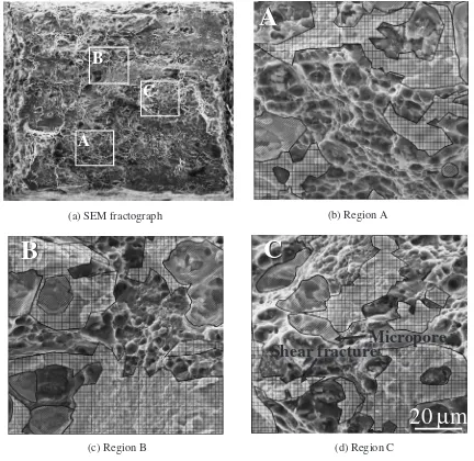
Figure 6(a) is an SEM image of a fracture surface and Fig. 6(b), (c) and (d) are magnified views of Fig. 6(a) on which hatched regions were identified as dimple patterns originating from the pre-existing hydrogen micropores. Areal
fractions of the dimple patterns originating from the pre-existing hydrogen micropores are 7.7, 28.2 and 16.6% for the regions shown in Fig. 6(b), (c) and (d), respectively. There-fore it can be concluded that at least in some cases hydrogen micropores make contributions to ordinary ductile fracture that cannot be disregarded. It is noteworthy that the dimple patterns originating from the pre-existing hydrogen micro-pores appear to be coarse compared to those originating from damage initiation during loading. Figure 7 demonstrates the contribution of a hydrogen micropore on the formation of the fracture surface on virtual tomographic slices. It is obvious that the relatively coarse micropore was nucleated onto the coarse particle and that the micropore grew in both the loading and transverse directions, especially elongating in the loading direction. The coarse micropore has been left at the bottom of the dimple.
Local image analysis for the three regions shown in Fig. 6(b), (c) and (d) was performed and the result is summarized in Table 2. Cubic regions of 100100
100mm were identified with the fracture surfaces as their vertical center in the 3D image captured before loading. In
(a) SEM fractograph (b) Region A
(c) Region B (d) Region C
20
µ
m
Micropore
Shear fracture
C
A
A
B
B
A
C
B
C
[image:4.595.82.514.73.493.2]the region with the highest micropore contribution, which is shown in Fig. 6(c), local volume fraction of micropore and number density were relatively high compared with the other regions, while no remarkable difference was observed in mean and maximum micropore size. It can be inferred that the agglomeration of hydrogen micropores might cause significant affects on mechanical properties.
4. Discussion
The relationships between metal working and micropore healing were reported in some early works. It has been reported that secondary porosity in aluminum alloys does not close through extensive deformation by hot and cold roll-ing.4)Direct observation of healing/reopening during plastic
working and subsequent heat treatments also revealed the morphologically variable behaviors of micropores during 60% compression.15) For example, some micropores
re-mained even after 60% compression, while others were apparently annihilated within the limited resolution of the tomography setup used. Some of the annihilated micropores were reinitiated again at their original positions before annihilation, even when an822% macroscopic strain had been applied after their apparent annihilation. This suggests that the effects of micropores on mechanical properties are inevitably assumed more or less due to the difficulty in the complete healing of micropores.
When the contribution of micropores on mechanical properties is not neglectable, a microstructural control, which
is different from the currently available common knowledge, might be needed. For examples, high-temperature heat treatments are performed on metallic materials with the aim of the eliminating segregation and coarse intermetallic particles and/or solutionization. However, in the light of the findings of the present study, heat treatment conditions should be controlled such that micropore growth is sup-pressed. This is because hydrogen micropores are reported to grow during high temperature exposure.12)
Since micropores tend to lie along (former) grain bounda-ry, there seems to be some anisotropic effect on the strain redistribution due to the existence of micropores.13) A 3D finite element simulation, which is based on actual 3D images, has demonstrated local stress and strain distributions in a similar 2024 aluminum alloy.13)Local strain elevation
was predicted to be 50–200% in the vicinity of micropores aligned along grain boundary. It can be inferred that ductile fracture would be promoted more considerably in such a case. Solution strengthening type aluminum alloys generally exhibits less dispersion particles. In such a case, greater effects might be expected. It is now being examined with more sophisticated technique than the present study and will be reported shortly.
5. Summary
Synchrotron X-ray microtomography was used to observe hydrogen micropores and their behaviors during deforma-tion and fracture in a 2024 aluminum alloy. High-density
(a) Before loading
(b) Fracture surface
Fracture path
Particle
Micropore
Al
Particle
Micropore
Micropore
20
µ
m
Air
Al
[image:5.595.116.484.73.295.2]Fig. 7 Tomographic slices representing micro-pores heterogeneously nucleated on a particle where a crack passed during fracture.
Table 2 Volume fraction, mean size and number density of micropores within the regions analysed.
Areal fraction of micropore on fracture surface, %
Volume fraction,
Vf/%
Mean diamater,
d/mm
Number density, 1012
p/m3
Region A 7.7 0.2 5.4 28.2
Region B 28.2 0.3 5.0 51.8
Region C 16.6 0.2 5.4 23.5
[image:5.595.46.550.343.422.2]micropores were observed in the alloys even before loading. Since hydrogen micropores are heterogeneously nucleated on particles, the pre-existing hydrogen micropores and voids caused by damage cannot be distinguished from their morphology. Although porosity for the material was relatively low, extensive growth of pre-existing hydrogen micropores have been observed during tension. The hydro-gen micropores started to grow from an early stage, while the ordinary damage initiation increased rapidly after plastic strain has been accumulated to some extent. Areal fraction of the dimple patterns originating from the pre-existing hydrogen micropores was approximately 728% on the fracture surface. It has been concluded that the hydrogen micropores more or less make contributions to ordinary ductile fracture.
Since the contribution of micropores on mechanical properties was proved not to be neglectable, the necessity of a microstructural control, which is different from the currently available common knowledge, was suggested.
Acknowledgements
The synchrotron radiation experiments were performed with the approval of JASRI through proposal numbers 2006A1056, 2007A1618 and 2007B1078. This work was undertaken as part of a Grant-in-Aid for Scientific Research (A) from the JSPS, as subject No. 20246102. The authors thank Dr. H. Tanaka in Sumitomo Light Metal Ind. Ltd. for providing materials used. One of the authors (HT) is also
grateful for the support of the Light Metal Educational Foundation.
REFERENCES
1) G. Itoh and M. Kanno: KINZOKU66(1996) 599–610.
2) G. A. Young Jr. and J. R. Scully: Acta Mater.46(1998) 6337–6349. 3) R. A. Outlaw, D. T. Peterson and F. A. Schmidt: Metall. Mater. Trans.
A12A(1981) 1809–1816.
4) D. E. J. Talbot: Inter. Metall. Rev.20(1975) 166–184.
5) O. Kubaschewski, A. Cibula and D. C. Moore:Gases and metals, (Iliffe books, London, 1970) p. 32.
6) H. Toda, I. Sinclair, J. Y. Buffie`re, E. Maire, K. H. Khor, P. Gregson and T. Kobayashi: Acta Mater.52(2004) 1305–1317.
7) L. Qian, H. Toda, K. Uesugi, T. Kobayashi, T. Ohgaki and M. Kobayashi: Appl. Phys. Lett.87(2005) 241907.
8) H. Toda, T. Ohgaki, K. Uesugi, M. Kobayashi, N. Kuroda, T. Kobayashi, M. Niinomi, T. Akahori, K. Makii and Y. Aruga: Metall. Mater. Trans. A37A(2006) 1211–1220.
9) L. Li, H. Toda, T. Ohgaki, M. Kobayashi, T. Kobayashi, K. Uesugi and Y. Suzuki: J. Appl. Phys.102(2007) 114908-1-9.
10) M. Kobayashi, H. Toda, Y. Kawai, T. Ohgaki, K. Uesugi, D. S. Wilkinson, T. Kobayashi, Y. Aoki and M. Nakazawa: Acta Mater.56 (2008) 2167–2181.
11) L. Qian, H. Toda, K. Uesugi, M. Kobayashi and T. Kobayashi: Phys. Rev. Lett.100(2008) 115505.
12) H. Toda, T. Hidaka, M. Kobayashi, K. Uesugi, A. Takeuchi and K. Horikawa: Acta Mater.57(2009) 2277–2290.
13) M. Kobayashi, H. Toda, K. Minami, T. Mori, K. Uesugi, A. Takeuchi and Y. Suzuki: J. Japan Inst. Light Met.59(2009) 30–34.
14) T. Hidaka, H. Toda, M. Kobayashi, K. Uesugi and T. Kobayashi: J. Japan Inst. Light Metal58(2008) 58–64.