Water reservoirs, estuary barrages, and other set-ups are built at either the set-upstream or downstream of rivers for developing water sheds in a country like Japan with scarce flat planes but with extensive mountainous regions. However, the flow interrup-tion may induce degradainterrup-tion of water quality, mud-diness of water, and insufficient supply of good-qual-ity water downstream, resulting in the occurrence of agricultural and fishery problems. Especially in the case of water reservoirs constructed with a dam, water environmental problems due to water quality pollutions caused by the development of the flow regions may occur in addition to the problem of stratified water. One of the reasons is related to wa-ter stagnation within the reservoir and is extended to density stratification and the problems due to eutrophication of algal bloom. These problems oc-cur once a year or half a year in Japan. The problem of eutrophication in lakes and ponds has prevailed throughout Europe as reported by Vollenweider (Vollenweider & Kerekes 1981) and Forsberg (Forsberg 1987). Meanwhile in Japan, a method was developed for the water quality improvement through the use of bubble plume in a step stratifica-tion (Asaeda et al.1991). A field survey and analysis were performed on the internal movement induced
by wind which occurred in a thermally stratified reservoir (Michioku et al. 1994). As a new method, micro-sized bubbles were supplied to enhance the activation of micro-organisms within the enclosed water region (Oonari 2003). Although a substantial effort has been directed to monitor and ascertain the effectiveness of these methods, the inherent environmental and economical problems have not yet been sufficiently resolved.
In the era of 1990s, the present authors engaged in the visualisation studies of inter-connected converg-ing and divergconverg-ing flow regions in x-shaped intersect-ing flows (Zhang et al. 1993; Umeda & Yang 1993). Different flow characteristics were disclosed in the crossing channels with different intersecting angles (Umeda et al. 1994). A diamond-shaped cylinder bundle was employed with an advancement in the network flow and subsequently a self-sustained flip-flop flow was discovered (Umeda & Yang 1996a; Umeda et al. 2007a). Through utilising the unusual pressure gradient induced by the ramming effect which occurred at the narrowest flow cross section of the intersection region in the crossing chan-nels, a reservoir model was developed to improve water-quality environment with the destruction of thermal stratification inside the reservoir (Umeda &
A study on applications of intersecting flows in water
reservoir for improvement of water environment problems
S. Umeda
1, W.-J. Yang
21
Department of Architecture and Civil Engineering, Fukuyama University, Fukuyama,
Hiroshima, Japan
2
Department of Mechanical Engineering, University of Michigan, Ann Arbor, Michigan, USA
Abstract: This paper deals with the applications of intersecting flows for the improvement of water environments in water reservoirs. First, the present authors’ research results are summarised for flow characteristics in intersecting chan-nels placed in horizontal or vertical positions. All physical phenomena involved are identified and their mechanisms are explained. Subsequently, appropriate methods are obtained for solving the problems of stratified water and eutrophica-tion in water reservoirs. A novel drainage system is developed and a particle ejeceutrophica-tion experiment for sediment flushing is investigated utilising a reservoir model with glass beads replacing sands. Flow visualisation and measurements are used in each experiment. The study has concluded that intersecting flows are suitable for solving water environment problems in water reservoirs.
Yang 1998a). The generation of micro-bubbles was also disclosed in diamond-shaped cylinder bundles through utilising the ramming effect (Umeda et al. 2007b). Thus, the intersecting flow yields, from flu-ids engineering viewpoint, various interesting flows depending upon the intersecting angle. In addition, self-excited oscillating jet streams with flip-flop flow can be produced not only in diamond-shaped cylinder bundles but also in staggeringly-arranged circular or rectangular cylinder bundles (Umeda & Yang 1998b; Umeda & Yang 1999). Furthermore, their efflux jet streams form multiple jet streams with uniform-flow rate (Umeda et al. 2007c) and may be utilised to develop economical and environ-ment-friendly fluid engineering devices.
The present study summarises the intersecting-flow characteristics obtained from the authors’ research results, introduces visualisation results of flows within vertically intersecting channels and the results from the particle ejection experiments in a reservoir model with glass beads for replacing sands, and provides some ideas on the applications of intersecting channels and flip-flop flows to water reservoirs.
Intersecting flows Motivation of study on intersecting flows
Many network flows exist in natural science area, consisting of various converging or diverging flows. For example, the river flow and blood flow are formed mostly through either converging or diverging flows with the exception of straight and bent flow portions. In the case of the city-water supply systems, flow rates are determined by taking into account the shape of the channel networks, the resistance of each node due to the friction loss, and the presence of either converging or diverging flows. Research had been
conducted on flows within soils and engineering de-vices which have plenty of converging and diverging flows and flows over obstacles.
However, upon a careful investigation of the main flow stream around objects, for example the portion in between two objects within a staggeringly-ar-ranged rectangular cylinder bundles, one observes two streams move from the upstream side of each object toward the central portion and collide and subsequently depart at the downstream side of the object. In other words, a converging flow and a diverging flow form an interconnected x-shaped flow. Such an x-shaped form of inter-connected converging and diverging flows has been named intersecting flow by the present authors (Zhang et al. 1993; Umeda & Yang 1993; Umeda et al. 1994). The region from the converging flow to the tip of the diverging flow is referred to as intersecting region, while the intersecting angle refers to the angle of intersection between the flow paths of the converg-ing and divergconverg-ing flow regions before and after the intersecting region. Inside the intersecting region, the cross-sectional area changes as the flow proceeds and thus creates a very complicated and interest-ing flow phenomena from the fluids-engineerinterest-ing viewpoint. Yang, one of the present authors, was the first to undertake a flow visualisation study on the x-shaped intersecting flow paths beginning in the year of 1990 (Zhang et al. 1993) and was followed by an other author, Umeda, the next year (Umeda & Yang 1993; Umeda et al.1994) in the exploration of various characteristics of the intersecting flow. There are two special features in intersecting channels:
(a) the converging and diverging flows following the cross-sectional area change in the intersecting region are inter-connected,
[image:2.595.74.321.580.756.2](b) geographically, like extra branches being at-tached on the winking portion of the channel from
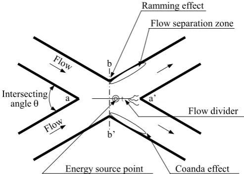
Figure 1. Schema of flows in an intersecting duct
� Ģ Intersecting
angle T
Flow
Flow a
b
b’
a’
Ramming effect Flow separation zone
Energy source point Coanda effect
both the upstream and downstream directions, in other words, the intersection region attached with extra channels both in front and from behind.
In regard to the special feature (a), like the pos-sibility of creating a new unit by combining units of different dispositions, it is feasible to impose a substantial influence on the diverging flow by vary-ing the convergvary-ing flow angle, just like to drive in a wedge in the diverging flow region. This is never seen in the single diverging flow case. As to the special feature (b), it can be expected to create a new idea through utilising available extra factors, although the presence of extra channels may also result in various harmful effects.
In the 21st century, an elucidation of the complex network flows is demanded. For fluids engineering with the effort being focused on intersecting flows, it is conceivable to make good use of the above two special features of intersecting channels.
Characteristics in intersecting flows
Figure 1 is a schema of flows in an intersecting duct. Here, left or right refers to its respective posi-tions in the flow direction. The inner wall refers to those intersecting channel walls which are confined within the central longitudinal lines, while the outer wall corresponds to the left and right walls outside the central longitudinal lines. Flows from both the left and right upstreams of the intersecting channels collide in the converging-flow region of the intersec-tion secintersec-tion. As a result, the b-b’ cross secintersec-tion where the cross-sectional area is narrowest is characterised by a large pressure gradient (Zhang et al. 1993) with a higher pressure in the central portion and negative pressure at both ends. This phenomenon is seen to occur as the push-in pressure at the air intake entrance (compressor) of jet aircrafts and is known as ramming or ramming effect. In the diverging flow region, due to the contraction of the converging flow streams, it creates an energy source point (Umeda et al.1994) on the a-a’ cross section in the intersection section where the flow speed becomes maximum while the pressure is minimum. Accompanying the flow separation from the left and right inner walls is the generation of vortices (Umeda & Yang 1993, called separation vortices). Simultaneously, von Karman vortex-street oscilla-tions take place as the Reynolds number (Re) is in-creased. The Coanda effect (Yang & Umeda 1998), the adherence of flow streak-lines on a surface, acts near the outer walls of the intersecting channels in the intersection section. In addition, a shear layer is formed like a wall on the central longitudinal line (a-a’) in the intersection section which is caused by
the collision of the flows. This shear layer undergoes a random fluctuation (Umeda & Yang 1996b) near the branching point (a’).
It is shown that the crossing flow having inter-connected converging and diverging flow regions is characterised by many special flow features. When intersecting channels are developed into a network channel, multiple crossing flows are formed with the occurrence of flip-flop phenomenon (Umeda & Yang 1996a) similar to a switching motion of a fluidic element. Depending upon the arrangement conditions, one may observe the crossing of the main streams and the formation of a longitudinal vortex (Hasegawa et al. 2004) which is a very interest-ing event in fluids engineerinterest-ing. The self-sustained flip-flop flow oscillation induces the formation of multiple efflux jet streams with a uniform flow rate (Umeda et al. 2007c) at the exit from the network channels.
With regard to the geometrically related special feature (b), it is feasible to vary the flow rate from the left and right upstream channels to yield differ-ent distributions or a combination of desired flow rate. In other words, to make the intersection section function like a faucet-free valve for applications in the flow control. For example, it is disclosed that a crossing flow channel with 60° intersecting angle (Umeda & Yang 1995) has equal efflux flow rate even under different left and right upstream supply rates. In this instance, the left and right downstream efflux rates are made equal and thus the outgoing flow-rate mixing ratio of the downstream channels would be determined by the input supply flow-rate ratio of the upstream channels.
On the other hand, through the sealing of one upstream channel in Figure 1, the suction phenom-enon induced by a rotating vortex in the intersection section (Yang & Umeda 1998) can be produced to enhance significantly the downstream efflux flow rate. All these phenomena occur through utilisa-tion of extra channels attached in front of and from behind the intersection section.
for stirring/mixing and washing; and others. In ad-dition, the incorporation of longitudinal vortices generated in flip-flop flow with slit flows can be utilised to produce stable liquid films (Umeda et al. 2007c) which can contribute to the development of air curtains and devices for foods preservation and working-environment protection.
Vertical intersecting flows
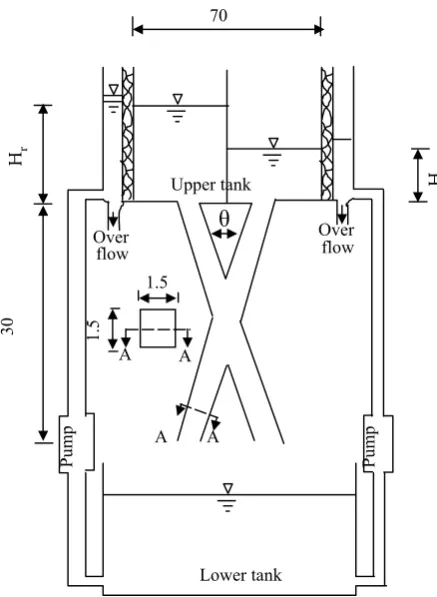
The upstream ends of the vertical intersecting channels are connected to the left and right tanks, as illustrated in Figure 2. No water is supplied to the left tank. Experiments are performed with the head of the right tank (Hr) varied while the upstream end connected to the left tank is either open or closed.
The channel cross section is a square of 1.5 × 1.5 cm2 area with the length of both channels fixed at 30 cm. The intersecting angle θ is selected as 30°, 60° and 90°, while the Reynolds number is varied within the range of 2.8 × 10⁴ and 5.5 × 10⁴. The Reynolds number is defined using the channel length as the characteristic length and the mean flow speed as the characteristic velocity. The Froude number is defined using the width of the channel as the characteristic length, and it is varied within the range of about 5.0 and 9.0.
Flow patterns
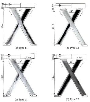
Flow patterns inside the intersection section vary depending upon the right tank head and the open/lose condition of the left tank. It is due to the generation of Coanda effect, adherence of streak-lines on the channel wall, depending on the pressure inside the intersection section and the flow velocity in the right-side tank. The flow patterns observed may be classified into four categories, Types 11, 12, 21 and 22, as listed in Table 1. The four flow patterns obtained for the intersecting angle of 60° are shown in Figure 3.
It is seen in Figure 3a for Type 11, that when the upstream end is open, the flow comes from the in-tersection section and exits from both downstream channels. However, if a slight amount of water flows into the left upstream end or if the left downstream channel end is temporarily adjusted, then the Coanda effect occurs as displayed in Figure 3b with most liquid leaving from the left downstream chan-nel. This is Type 12 flow pattern. In the case that the upstream head is at its lowest level of 11.5 cm, the flow pattern of Figure 3a fails to occur but instead, the flow takes the pattern of Figure 3b. When the left upstream end is closed, the left upstream channel becomes a sealed chamber as soon as the right-side flow begins with the pressure in the intersection section diminishing. As a result, near the centre of the intersection section is confined to a minimum cross-sectional area, while the flow expands its cross section and enters into the left upstream channel. Hence, the flow velocity near the intersection sec-70
ș
1.5
1.
5
Over
flow Overflow
Lower tank
Unit:cm
Hl Hr
30
Upper tank
Pump
Pump
A A
[image:4.595.64.283.57.356.2]A A
Figure 2. Schema of experimental apparatus with a vertical intersecting duct (in cm)
Table 1. Kinds of flows in a vertical intersecting duct
Type Hl = 0.0 condition Characteristics of flow
11 open No Coanda effect – flow in two ducts 12 open Coanda effect – flow in almost one duct 21 close Suction, Coanda effect – flow in two ducts 22 close Suction, Coanda effect – flow in almost one duct
Hr
[image:4.595.63.542.670.757.2]Figure 3. Flow patterns in a vertical intersecting duct; (a) Type 11, (b) Type 12, (c) Type 21, (d) Type 22
(a) Type 11 (b) Type 12
(d) Type 22 (c) Type 21
tion is increased and the right tank head falls from its pre-set value of 30 cm to 28.5 cm because the pump is set to supply the same flow rate to the right upstream tank. This is Type 21 flow pattern shown in Figure 3c. The downstream end condition may be set to produce Type 22 flow pattern shown in Figure 3d.
Next is the θ = 30° case (flow patterns not shown). When the left upstream end is open, the vertical down flow is large near the intersection section and most flow exits from the right downstream channel without the Coanda effect for the fluid to adhere on the right channel wall. This is Type 11 flow pattern. However, when the left upstream end is closed, a good amount of the fluid exits from the left down-stream channel and a large separation vortex appears behind the left intersection section compared with the case when the fluid is supplied from both sides. This is Type 21 flow pattern. Only the above two types of the flow pattern prevail even with the adjust-ment of the upstream tank head condition.
Finally, the intersecting angle of 90° yields four different flow patterns like θ = 60° case.
Suction effect in converging region
Let us compare the flow behaviour of Types 11 and 21. The former has the left upstream channel
end open and without Coanda effect, while the latter has the end closed and with both the Coanda and suc-tion effects. The velocity [2g(Hu + z)]1/2 and mass flux Q/A, both with the same unit of cm/s, are deter-mined and their relationship is plotted in Figure 4. Here, Hu denotes the upstream tank head; z, posi-tion; Q, mass flow rate; and A, cross-sectional area of each flow channel. It is seen in the figure that Type 21 with the upstream channel end closed yields higher mean flow velocity than Type 11 with the end open. For the same upstream tank head and intersecting angle of 30°, the mean flow velocity in Type 21 is approximately 45% higher than that in Type 11. Inside this intersecting channel, a rotating vortex is formed in between the channel cross section and the enclosed space to expand the channel cross section in the Type 21 case. This phenomenon together with the double of the downstream channel cross section (as the flow exits from both left and right channels) results in an enhancement of the mean flow velocity. In other words, the suction effect is produced to call in the fluid into the intersection section.
Characteristics in flow rates
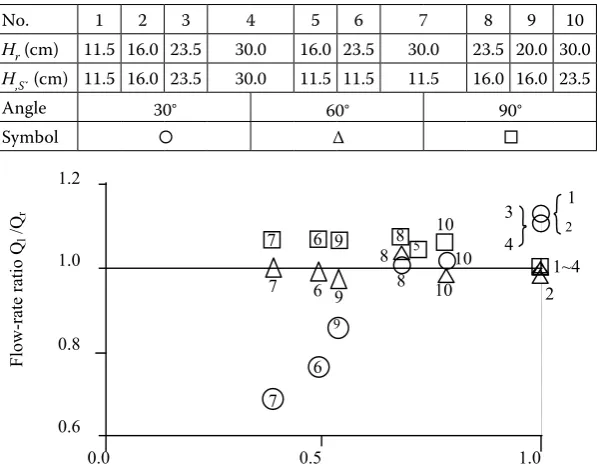
The variations in the flow rate at both downstream ends are investigated in response to the changes in the upstream tank head caused by differences in the intersecting angles. Figure 5 displays the relationship between the head ratio Hl/Hr and the flow-rate ratio Ql/Qr, where the subscripts l and r denote the left- and right-side channels, respectively. In the θ = 30° case, Ql/Qr takes a value of approximately 1.1 in all four cases having the head symmetry. This means more flow through the left channel. As observed
in the horizontal intersecting channels (Umeda & Yang 1993), this phenomenon is induced by the formation of a separation vortex which is in sym-metrical shape behind the intersection section, even the left and right upstream heads are held symmetri-cal. In the event when the heads are asymmetrical with a higher right tank head, the right downstream flow rate Qr becomes higher but Ql/Qr diminishes with a decrease in Hl/Hr. In contrast, in the θ = 90° case, the left downstream flow rate Ql is higher even with lower left tank head. In addition, a change in the upstream head causes a smaller change in the flow rate Ql and Ql/Qr remains practically con-stant. For θ = 60°, irrespective of Hl/Hr value, Ql/Qr takes a value of nearly unity. According to the flow visualisation photographs of horizontal intersecting channels (Umeda & Yang 1993), when the supply flow rates in the left- and right- upstream channels are different, the fluid from the higher right chan-nel flows into the left downstream chanchan-nel via the intersection section. This causes asymmetry in the left and right separation vortices which are formed behind the intersection section. This asymmetry is especially evident, with the left separation vortex being smaller. In the θ = 60° case, the left separation vortex appears in somewhat round shape.
[image:6.595.63.293.55.276.2]Thus, the distribution characteristics of the flow rates from both downstream ends are disclosed to be dependent upon the upstream supply flow rate and the intersecting angle. Of particular importance is θ = 60° case with the flow rates from both down-stream ends being almost equal. It implies that the
Figure 5. Relationship between Ql/Qr
and Hl/Hr in vertical intersecting duct
Type 30� ‹60� ‹90� ‹
1 � › � �
21 �Ğ �à �
x10 2 2.7 3.0 3. 5 3. 0 2. 5 1. 9 3.5 M ea n ve lo ci ty in in te rs ec tio n Q d/ A (c m /s ) (cm/s) 2g(Hu+z)
Mean velocity in upper tank
M ea n ve lo ci ty in in te rs ec tio n Q d/ A (c m /s ) × 10 2
30° 60° 90°
∆
▲
[image:6.595.66.365.499.737.2]3.5 × 10²
Figure 4. Relationship between Qd/A and √2g(Hu+z)
No. 1 2 3 5 6 8 9 10
Hr (cm) 11.5 16.0 23.5 16.0 23.5 23.5 20.0 30.0
H‚ĝ (cm) 11.5 16.0 23.5 11.5 11.5 16.0 16.0 23.5
Angle
Symbol �› � �
7 30.0 11.5 60�‹ 90�‹ 4 30.0 30.0 30�‹ 7 5 1~4 10 8 6 7 6 7 9 8 8 6 9 9 10 10 2 2 1 4 3 1.2 1.0 0.8 0.6
0.0 0.5 1.0
Fl ow -r at e ra tio Ql /Q r
Head ratio in upper tank Hl /Hr
No. 1 2 3 4 5 6 7 8 9 10
Hr (cm) 11.5 16.0 23.5 30.0 16.0 23.5 30.0 23.5 20.0 30.0
H,Sˇ (cm) 11.5 16.0 23.5 30.0 11.5 11.5 11.5 16.0 16.0 23.5
Angle 30□‹ 60□‹ 90□‹
Symbol □› □› □
Hl/Hr
30° 60° 90°
∆
left and right upstream flow-rate ratio determines the mixing ratio of the downstream flow rates. Hence, the flow-rate distribution characteristics are very interesting in fluids engineering. It performs the function of faucet-free valve and may be developed for fluid control.
Finally, one should be reminded that the flow velocity and its variation in the intersection section change with a change in the intersecting angle. A comparison of the flow behaviour for the θ = 30° and 60° cases reveals that the former can be represented by a word unstable, while the latter by a word stable in their respective behaviour. In the application of intersecting flows the word unstable is relevant to oscillation fluid behaviour and is thus suitable in fluid mixing and diffusion phenomena. On the contrary, the word stable in the 60° angle case may yield interesting results in various flow controls for the equalisation and dispersion of the flow rates.
Applications of intersecting flows for improvement on water environmental problems
Since ancient times, human involvement with riv-ers has been that of struggles with flooding and utili-sation of water. As a proverb puts it “He who governs a country must manage water”. Thus, river/sand arrestation is a very important research area in civil engineering departments. A large number of dams have been constructed for the rivers improvement (i.e. control of water) and irrigation (i.e. water uti-lisation). However, numerous new water environ-ment problems have followed regional and urban development. Especially, proposals are invited for new technical developments taking into considera-tion the environmental protecconsidera-tion and economical problems. For the applications of intersecting flows, the following sections introduce some proposals on new development methods in connection with the dam-related water environment problems.
Stratified water and eutrophication Destruction of stratified water
In dams and water reservoirs, in addition to the thermally stratified water problems, environmental problems of water-quality contamination caused by basin development are produced. One of the reasons is related to water stagnation inside the reservoirs resulting in density stratification and eutrophication problems. Various methods have been proposed and investigated as water-quality improvement policy. However, the environmental and economic problems have not yet been ad-equately solved.
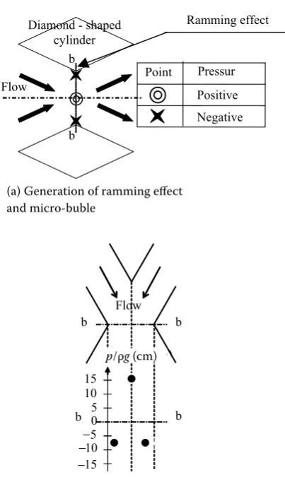
[image:7.595.310.512.339.677.2]Section 2 disclosed a very interesting pressure characteristics induced by the ramming effect inside the intersection section of intersecting channels. One of the pressure monitoring results is presented in Figures 6a, b. At the narrowest cross section in the intersection section where the converging and diverging flows are interconnected, the positive and negative pressure locations are shown in Figure 6a by the double circle (at the centre) and x ( near the edge of two adjacent cylinders) symbols, respectively. The piezo-head data taken along the narrowest cross section b-b are indicated in Figure 6b. These pres-sure differences induce a large prespres-sure gradient in the lateral direction, an evidence of the generation of the ramming effect. In other words, the pressure becomes maximum around the centre of the cross section and diminishes towards both left and right ends. Hence, with the installation of an ejection hole near the centre and suction holes near both ends, each flow circulation yields appropriate results.
Figure 6. Ramming effect and piezo head; (a) generation of ramming effect and micro-bubble, (b) results of piezo head at the narrowest section (b-b section)
(a) Generation of ramming effect and micro-bubble
Ramming effect
(b) Results of piezo head at the narrowest section (b-b section)
-15
� Ğ
� Ğ � Ğ � Ğ
� Ğ � Ğ
Flow
b b
b b
p/�g(cm) (cm) 15
10 5 0 -5 -10 Diamond - shaped
cylinder
Point Pressur
Positive Negative Flow
b
b
(a) Generation of ramming effect and micro-buble
(b) Results of piezo head at the narrowest section (b-b section)
–
––
p/ρg (cm)
In order to develop an environment-friendly method and to utilise water in reservoirs, the present authors have conducted basic experiments related to the application of network flows in the internal circulation system inside reservoir stratification. A visualisation experiment is performed on water movement inside a reservoir model. It is disclosed that, by using a jet flow from the network channel installed at the base of the reservoir model, water in the reservoir exhibits three-dimensional flow behav-iour. Hence, stirring and mixing of stored water can be expected and may be applied to the destruction of thermally stratified layers.
Generation of micro-bubbles
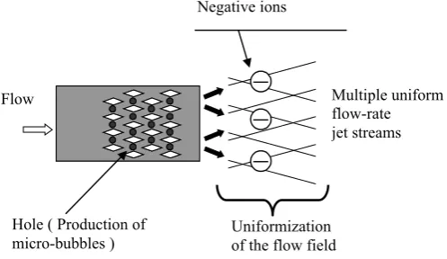
It has been discovered that a self-sustained flip-flop flow oscillation is generated in efflux jet streams from a diamond-shaped cylinder bundle having over four-row cylinders. It has been also confirmed (Umeda et al. 2007a) that this flip-flop flow becomes stable in such a diamond-shaped cylinder bundle with the cylinder number exceeding six rows. Fur-thermore, accompanying flow separation from the cylinders, the intersecting main streams inside the channels include a longitudinal vortex. When air is supplied to a small hole drilled near the x-symbol location between two adjacent cylinders, with an aid of the shearing action of the longitudinal vortex which rotates in the flow direction, many micro-bub-bles of less than several ten-micron size (Umeda et al. 2007b) are generated.
Inside a stagnant water district with eutrophica-tion in progress, microorganisms stop breeding due to an insufficient supply of oxygen caused by water stagnation. This is one of the reasons for the water-quality deterioration. Therefore, it is important to promote the breeding of microorganisms through increasing the amount of dissolved oxygen in the water district by means of supplying micro-bubbles. Through utilising a diamond-shaped cylinder bundle illustrated in Figure 7, multiple uniform flow-rate jet streams are formed in its efflux flow and
micro-bub-bles can be supplied to promote stirring and mixing over the entire water district. Another special feature is that such a device possesses economic character-istics of the utilisation of natural principles. New drainage system for selected intake and sedi-ment flushing(Umeda et al. 2000)
Estuary dikes and water reservoirs stagnate water flows, causing various water environment problems such as eutrophication and long-lasting turbid water. Various counter-measures for the reservoir water-quality conservation are reported (Niwa et al. 1993). Relevancy between vortex structure inside the intersecting flows and streak-line oscil-lations at the downstream ends has been disclosed (Umeda et al.1998). By utilising the special features of intersecting channels to control the flow-rate distribution through each channel, it is possible to (i) mix and discharge the waters which are extracted from different layers in a reservoir, and (ii) precisely control the flow rates from multiple intake ports by adjusting the suction force of each element in the intersecting channels.
Here, as described in the preceding section, the special characteristics of x-shaped intersecting channels are applied. We introduce a proposal regarding a water supply channel system for a new water reservoir which is to be used for both selec-tive water extraction and sand exclusion. With the use of this system, a selective extraction is possible of specified amounts of water from any depth by means of a delicate flow-rate adjustment. In ad-dition, muddy minute particles can be sucked up using one of the intersecting channels at a suction port installed near piled sand layers. This system is simple/basic principles and cheap in construction costs as compared with traditional establishments.
New drainage system
Figure 8 is a schematic diagram of the reservoir model using an intersecting duct which can be uti-lised for both water extraction and sand exclusion
Multiple uniform flow-rate jet streams
Uniformization of the flow field Flow
Hole ( Production of micro-bubbles )
[image:8.595.76.325.59.203.2]in the existing reservoirs. In consideration of the relationship between the extracted sand mass and gravitational action, one case is a vertical intersect-ing channel installed on the spillway shown in Figure 8a, and another form is a horizontal intersecting channel floating in the reservoir as illustrated in Figure 8b. In the latter case the left and right chan-nels being horizontally setup have their channel intake ports located, one near the water surface and the other near the reservoir bottom. Their down-stream channels are positioned to release water via their either flood gate or spill-over gate. This model in Figure 8c releases the reservoir water from the two upstream channels in a mixed fashion: At the flooding time, the channel valves installed near the
water surface are closed and the other channels at the reservoir base release the water mixed with mud and sands. In this instant, since the upstream channel ends are closed, suction functions in the intersection section (Yang & Umeda 1998). With the two downstream channels in use, much more water is discharged than that due to the siphon action on a single channel having the same cross sectional area.
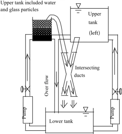
Experiments on sediment flushing
In order to verify this novel concept, discharge ex-periments are performed on a reservoir model with sand replaced with glass beads. The schema of the experimental setup is shown in Figure 9. The intersect-ing angle of 30° is employed. The left head tank serves only for water supply, while the right head tank stores water and glass particles. For convenience, the left upstream tank is referred to as high-pressure water tank, while the right upstream tank as siphon-use wa-ter tank. Two kinds of rectangular channels are tested: Type 1 with 1 cm × 1 cm cross section and Type 2 with 2 cm × 2 cm cross section. Three sizes of glass beads are employed: 1.2 mm, 3.7 mm and 5.0 mm of mean diameter denoted by S, M and L, respectively. The water supply conditions from both upstream tanks are varied to determine changes in mixing and glass beads discharge rate. Only the results on the glass discharge rate related to its supply are presented here.
First, the changes in the discharge flow rate and the amount of glass beads discharged from the
in-sp
ill
w
ay
Gate
(a) Front view
(b) Top view
[image:9.595.318.530.491.723.2](c) Side view
Figure 8. Schema diagram of reservoir model using an inter-secting duct; (a) front view, (b) top view, (c) side view
Figure 9. Schema of experimental apparatus with a vertical intersecting duct for a reservoir model
Upper tank (Left)
Lower tank
Pump Pump
Intersecting ducts
Over
flow
Upper tank included water and glass particles
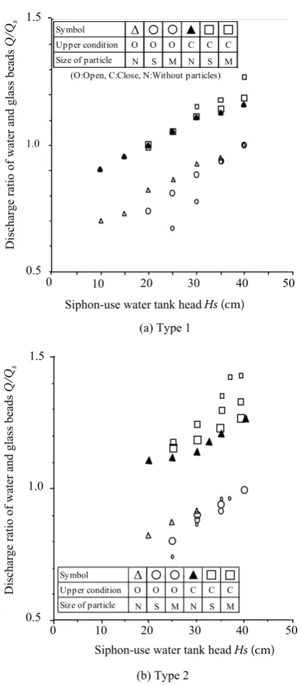
tersecting channels are determined in response to the changes in the siphon-use water tank head for two cases, i.e. when the left upstream end is open and when it is closed. The results are presented in Figures 10a, b. These figures demonstrate the ratio of the discharge rate of water and glass beads, Q, to the basic flow rate, Qs in response to the change in the siphon-use water tank head, Hs. Here, Q includes only the water flow rate when the left upstream end
connection is open and Hs = 40 cm. In the Type 1 case shown in Figure 10a, when only water is in the siphon-use water tank in the absence of glass beads, the ratio Q/Qs of both downstream ends increases linearly with an increase in Hs and reaches unity at Hs = 40 cm. Meanwhile, when the left upstream end connection is closed, Q/Qs increases just like in the open case but on average by about 20% more than in the open case. This can be attributed to the suction effect which occurs in the intersection sec-tion. In contrast, when the glass beads are put into the siphon-use water tank, the change rate of Q/Qs differs depending upon in glass-beads size. That is, a higher change rate for a smaller one particle size and smaller for larger particle size. These characteristics are very similar to the water-only case. Meanwhile, when the left upstream end connection is closed, ir-respective of the particle size, suction occurs only in the water-only case, with practically the same change rate in the discharge ratio.
Now, let us examine the results for Type 2 shown in Figure 10b. When the left upstream end connection is open, the Q/Qs ratio for both downstream ends in response to the change in Hs slightly varies with dif-ferences in the particle size. As a whole, the results are similar to those of Type 1. However, when the left upstream end connection is closed, the flow-rate ratio increases by approximately 30% compared to the open case. The amount of the change rate differs depending on the particle size. In other words, the discharge-rate ratio increases as the particle size diminishes. This is because the suction effect is en-hanced as the particle size is reduced in the channels with a larger cross section. It is clarified now that the discharge rate differs depending upon the size of the channel cross section, the size of glass beads, and the difference in the flow rate and the water supply rate from the left and right upstream water tanks. In particular, the utilisation of the suction effect is crucial for enhancing the discharge rate by means of raising the siphon-use water tank head when the connection between the high-pressure water tank and the intersecting channels is closed.
CONCLUDING REMARKS
Unusual climates such as floods and draughts prevail world-wide in accompany with global warming trend. Severe consequences in water en-vironment problems might follow. For the sake of environment improvement, the present work has introduced
[image:10.595.67.286.68.568.2](i) characteristics of intersecting flows with the intersecting angles of 30° and 60°,
Figure 10. Change of ratios of flow rates included particles in case of supplying only from right upper tank; (a) Type 1, (b) Type 2
D
is
ch
ar
ge
ra
tio
o
f w
at
er
a
nd
g
la
ss
b
ea
ds
Q
/Q
s
(a) Type 1
Siphon-use water tank head Hs (cm) 0
1.0 1.5
10 20 30 40 50
0.5
Symbol �� › � › �à� �
Upper condition O O O C C C
Size of particle N S M N S M
(O:Open, C:Close, N:Without particles)
D
is
ch
ar
ge
ra
tio
o
f w
at
er
and
glass
beads
Q/Qs
1.0
0.5
0 10 20 30 40 50
1.5
(b) Type 2
Symbol �� › � › �à� �
Upper condition O O O C C C
Size of particle N S M N S M
Siphon-use water tank head Hs (cm)
Q
/Qs
Q
/Qs
Hs (cm)
Hs (cm)
Δ ▲
(ii) multiple uniform flow-rate jet streams with self-excited oscillation from diamond-shaped cylinder bundles, and
(iii) generation of micro-bubbles.
New systems have been proposed for water ex-traction (i.e. drainage) and sand exclusion from water reservoirs. Intersecting flow is a new field, its research and development having being initiated near the close of the 20th century and is progressing at full steam now. It is a great challenge to develop and apply this new field for not only fluids engineer-ing related devices but also for agriculture, forestry, and nature at-large.
References
Asaeda T., Ikeda H., Imberger J. (1991): The structure and evolution of the bubble plume in a step stratification. Jour-nal of Hydraulic, Coastal and Environmental Engineering,
438/II-17: 23–30.
Forsberg C. (1987): Evaluation of lake restoration in Sweden. Schweizerische Zeitschrift für Hydrologie – Swiss Journal of Hydrology, 49: 260–274.
Hasegawa S., Umeda S., Taniguchi A., Yang W.-J. (2004): Flow visualization by means of PIV in a diamond-shaped cylinder bundle. Transactions of the Visualization Society of Japan, 24: 55–61.
Michioku K., Kanda T., Shigemura S. (1994): Field survey and analysis of internal motions observed in a thermally stratified reservoir. Journal of Hydraulic, Coastal and En-vironmental Engineering, No. 485/II-26, 65–73.
Niwa K. et al. (1993): Countermeasures for reservoir water quality conservation by water current control system. An-nual Journal of Hydraulic Engineering, 37: 271–276. Oonari H. (2003): Patent No. 3397154
Umeda S., Yang W.-J. (1993): Flow visualization methods in intersecting ducts. Journal of Flow Visualization and Image Processing, 1: 159–170.
Umeda S., Yang W.-J. (1995): Flow visualization in two intersecting vertical ducts – characteristics of resistance and flow rate. Transactions of the Visualization Society of Japan, 15: 273–278.
Umeda S., Yang W.-J. (1996a): Flow characteristics in multi-ple intersecting ducts. Journal of the Visualization Society of Japan, 16: 120–128.
Umeda S., Yang W.-J. (1996b): Dynamic behavior of shear layer in intersecting ducts. In: 9th Int. Symp. Transport Phenomena
in Thermal-Fluid Engineering. Singapore, 784–788.
Umeda S., Yang W.-J. (1998a): Improvement of water-qual-ity environment in reservoir models using flow networks. International Journal of Environment and Pollution, 10: 289–303.
Umeda S., Yang W.-J. (1998b): Flow through rectangular cylinder bundles. Journal of Flow Visualization and Image Processing, 5: 167–186.
Umeda S., Yang W.-J. (1999): Interaction of von Karman vortices and intersecting main streams in staggered tube bundles. Experiments in Fluids, 26: 389–396.
Umeda S., Yang W.-J. (2001): A laser Doppler velocimetry study of flow at the intersections of converging and di-verging ducts. Journal of Flow Visualization and Image Processing, 8: 81–90.
Umeda S., Yang W.-J., Tanaka T. (1994): Mechanics and correlations of flow phenomena in intersecting ducts. Experiments in Fluids, 17: 323–329.
Umeda S., Yang W.-J., Wu C.-S. (1998): Reciprocating bubble migration and flip-flop phenomena in multiple flow networks. In: 11th Int. Symp. Transport Phenomena.
Hsinchu, 415–420.
Umeda S., Yang W.-J., Horii K., Miyazaki T. (2000): Ex-perimental study on a new system of drainage ducts in a reservoir. Annual Journal of Hydraulic Engineering, 44: 903–908.
Umeda S., Hasegawa S., Yang W.-J. (2007a): Occurrence of flip-flop flows in diamond-shaped cylinder bundles. Journal of Environment and Engineering, 2: 1–12.
Umeda S., Wakabayashi T., Yamada K., Urakami K., Tsuji H., Yang W.-J. (2007b): Micro-bubbles/flip-flop mixed efflux from a diamond-shaped cylinder bundle. Journal of Flow Visualization and Image Processing, 14: 305–315. Umeda S., Shigeyama S., Iijima K., Sukehira C., Yang
W.-J. (2007c): Efflux from a composite flow network hav-ing flip-flop flow in parallel with slit flows. Journal of Flow Visualization and Image Processing, 14: 317–337. Vollenweider R. A., Kerekes J. (1981): OECD
Eutrophi-cation Programme. Synthesis Report. Organization for Economic Cooperation and Development, Paris.
Yang W.-J., Umeda S. (1998): Coanda effect and its role in mixing in intersecting flow. In: Proc. CSME FORUM SCGM 1998, Toronto, Vol. 1, 147–152.
Zhang N., Yang W.-J., Xu Y. (1993): Flow characteristics in flow networks. Experiments in Fluids, 14: 25–32.
Corresponding author:
Prof. Shinzaburo Umeda,Fukuyama University, Department of Architecture and Civil Engineering, Fukuyama, 729-0292 Hiroshima, Japan
e-mail: [email protected] Abstrakt
Umeda S., Yang W.-J. (2008): Studie aplikací protínajících se proudů ve vodních nádržích při nápravě vlivů okolního prostředí. Res. Agr. Eng., 54: 68–79.
Práce se zabývá aplikací protínajících se proudů ke zlepšení vodního prostředí ve vodních nádržích. Autoři poprvé sumarizují své vědecké výsledky týkající se protínajících se kanálů umístěných horizontálně i vertikálně. Mechanismy křížení jsou identifikovány a vysvětleny na základě fyzikálních jevů. Získávají se vhodné metody pro řešení problémů stratifikace vody a eutrofizace ve vodních nádržích. Je vyvinut nový drenážní systém a je zkoumána ejekce částic při sedimentačním splachování s použitím modelu skleněných kuliček nahrazujících písek. Vizualizace proudění, včetně jeho proměřování je využita v každém experimentu. Studie ukázala, že protínající se proudy jsou vhodné pro řešení problémů vznikajících ve vodních nádržích.