Closed Recycling Process for Al-Based Composite Materials
Hiroyuki Sano
1, Shinichi Kato
2;*1, Tatsuya Motomura
2;*2and Toshiharu Fujisawa
11EcoTopia Science Institute, Nagoya University, Nagoya 464-8603, Japan
2Department of Materials Science and Engineering, Graduate School of Engineering, Nagoya University, Nagoya 464-8603, Japan
Closed recycling process for low-grade scrap of Al-based composite materials was developed. Flux treatment with water-soluble halide is a key technique in this process. In the present work, flux treatment conditions were discussed from the viewpoints of separation and recovery of base material, reinforcement and flux. Optimum separation condition was obtained for the NaCl–KCl–KF flux treatment. The recovered aluminum alloy can be recycled for various usages. The recovered SiC particles cannot be reused as reinforcement because of the coexistence of contamination, therefore it is necessary to eliminate these contaminates or to find the other uses. The recovered flux is reusable with supplemental addition of fluoride.
(Received June 27, 2005; Accepted September 6, 2005; Published December 15, 2005)
Keywords: composite materials, recycling, aluminum alloy, potassium fluoride, flux treatment, recovery
1. Introduction
Composite materials demonstrate a more excellent char-acteristic in combining materials with various properties.1–3)
Therefore, they are being used in various fields. A particle reinforced Al-based composite material is one of the typical metal matrix composite materials.4) It is used for various components such as automotive brake disks, engine parts and so on, because of the lightweight, high thermal conductivity and high wear resistance.5)The application of this composite is expected to be expanded and, therefore, a large amount of by-products and waste will be generated from the manufac-turing process in the near future.
High-grade scrap can be re-melted and directly reused, while low-grade scrap cannot be re-melted because of the contamination of the aluminum melt by impurities such as oxides.6,7)Therefore, it is needed for the recycling of the
low-grade scrap to develop the separation and recovery method of the base material and the reinforcement.8–10)However, it is
not easily to separate the base material and the reinforcement, because the particle reinforced Al-based composite material is not produced by considering recyclability but by focusing on high performance. So an effective recycling technology for the particle reinforced Al-based composite material has not been established.
In the present work, scraping waste of the Al–SiC composite material, which is one of the typical particle reinforced composite materials, was selected as low-grade scrap. It was aimed to separate the scrap to the aluminum alloy, base material, and the SiC particles, reinforcement, by using a water-soluble flux treatment at elevated temperature, and to recover the both at reusable conditions.11) The
conceptual flow of the proposed closed recycling process is shown in Fig. 1.
2. Experimental Method
Scraping waste generated in the manufacturing process of the automotive brake disks was used. It consists of Al– 8.5%Si alloy and 20 vol%SiC particles as reinforcement. Table 1 shows the water-soluble fluxes used in the present work and the experimental temperatures. In order to transfer the SiC particle to the flux, it is required that the wettability of SiC and flux is larger than that of SiC and aluminum alloy.
Al-Based Composite Material
(e.g. Al-SiC)
Base Material (e.g. Al Alloy)
Reinforcement (e.g. SiC) Water-Soluble
Flux
Flux Leaching in Water Water-Soluble
Flux Treatment Filtration and Drying
Residue Filtrate
[image:1.595.309.545.298.460.2]Fig. 1 Conceptual flow of the proposed closed recycling process.
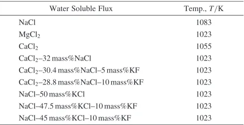
Table 1 Fluxes used in this research and experimental temperatures.
Water Soluble Flux Temp.,T/K
NaCl 1083
MgCl2 1023
CaCl2 1055
CaCl2–32 mass%NaCl 1023
CaCl2–30.4 mass%NaCl–5 mass%KF 1023
CaCl2–28.8 mass%NaCl–10 mass%KF 1023
NaCl–50 mass%KCl 1023 NaCl–47.5 mass%KCl–10 mass%KF 1023 NaCl–45 mass%KCl–10 mass%KF 1023
*1Graduate Student, Nagoya University. Present address: Taiho Kogyo
Co., Ltd., Toyota 471-8502, Japan
*2Graduate Student, Nagoya University. Present address: Saganoseki
Smelter & Refinery, Nippon Mining & Metals Co., Ltd., Oita 879-2201, Japan
[image:1.595.306.549.514.639.2]However, it has no available data about wettability of SiC and flux.12,13) Thus, the flux was selected based on the
following points, large solubility to water, low melting temperature, and low price. In case when the melting temperature of the flux is lower than 1023 K, experimental temperature was 1023 K, and in the other cases it was 10 K higher than the melting temperature of flux.
About 20 g of the flux was charged into a graphite crucible (I.D. 35 mm, L. 140 mm) and heated in an electric furnace at a desired temperature under an argon atmosphere. After the flux was melted, scraping waste of the Al–SiC composite material of the same volume as the flux was put into the flux melt and stirring by Al2O3 rod was continued for 3.6 ks
(250 rpm). Then, by settling for 3.6 ks, aluminum alloy and flux were separated by the specific gravity difference. The sample was poured from the crucible into a water-cooled copper mold to quench rapidly.
After the experiment, the sample was soaked in about 200 cm3 of deionized water at room temperature. Only the
flux was dissolved in water, and the recovered aluminum
alloy was collected from the solution and the chemical composition of the alloy was analyzed by ICP-AES. Next, the water dissolving flux was filtrated to separate into the residues and the filtrate. The residues were dried and the mass was measured, then the carbon content was analyzed by the combustion coulometric titration method to calculate the amount of recovered SiC. Impurities other than SiC included in the residues were identified by the X-ray diffraction analysis and SEM-EDX. The flux was recovered from the filtrate by evaporating water. It was subjected to the X-ray diffraction analysis. The chemical compositions of flux before and after the treatment were analyzed by ICP-AES and the ion chromatography.
3. Results and Discussion
3.1 Recovery ratio of SiC
A SiC recovery ratio,RSiC, was defined by the following
equation:
RSiC=%
½Mass of SiC Transferred to the Flux
½Mass of SiC Initially Included in the Specimen100 ð1Þ
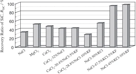
Figure 2 shows the SiC recovery ratio by each flux.
3.2 Treatment without fluoride
When the flux treatment was conducted by the flux that did not contain the fluoride (KF), the recovery ratio of SiC was less than 60%. In addition, the aluminum alloys were recovered only as granulated form [see Fig. 3(a)]. The surface of granules was completely covered by some depositions. The depositions were identified as SiC and Al2O3 by the X-ray diffraction analysis. It was considered
that the deposited SiC particles disturbed the coalescence of aluminum alloy. Thus, the recovery ratio of SiC was low and it was difficult to recycle the recovered aluminum alloy under these conditions.
3.3 Treatment with fluoride by the CaCl2–NaCl–KF flux
It is necessary to improve the wettability of the flux system in order to recover the lump of aluminum alloy and to improve the recovery ratio of SiC. Fluorides decrease the
interfacial tension between the aluminum alloy and the flux.14–16)Then, a new set of experiments was conducted by using fluoride-added flux. In consideration of the solubility to water, KF was selected as the additive fluoride.17)
When 5 or 10 mass% of KF was added to the CaCl2–NaCl
0 20 40 60 80 100
NaCl MgCl2 CaCl
2
CaCl
2-32%NaCl
CaCl
2-30.4%NaCl-5%KF
CaCl
2-28.8%NaCl-10%KF
NaCl-50%KCl
NaCl-47.5%KCl-5% KF
NaCl-45%KCl -10%KF
Recovery Ratio of SiC,
RSiC
/ %
Fig. 2 Recovery ratios of SiC by various flux treatments.
10 mm
10 mm
(a)
(b)
10 mm
10 mm
Fig. 3 Appearance of recovered aluminum alloy (a) by the CaCl2–32%NaCl flux treatment, and (b) by the CaCl2–30.4%NaCl–5%KF flux
[image:2.595.314.541.463.587.2] [image:2.595.116.484.628.759.2]flux, the aluminum alloy was still recovered as granulated form the same as the treatment by the flux without KF [see Fig. 3(b)]. The recovery ratio of SiC was also not improved. The fluoride addition to the CaCl2–NaCl system flux was not
effective.
As the existence of CaF2in the flux was identified by the
X-ray diffraction analysis, it was considered that the follow-ing reaction took place durfollow-ing the flux treatment:
CaCl2ðlin fluxÞ þ2KFðlin fluxÞ
!CaF2ðlin fluxÞ þ2KClðlin fluxÞ ð2Þ
Therefore, the effect of the KF addition did not result in the improvement of the wettability.
3.4 Treatment with fluoride by the NaCl–KCl–KF flux
When 5 or 10 mass% of KF was added to the NaCl– 50%KCl flux, a lump of aluminum alloy was recovered (see Fig. 4). The recovery ratio of SiC was improved to almost
100% as shown in Fig. 2. In this flux treatment, it is considered that the SiC particles moved completely into the flux phase and the aluminum particles could coalesce into a large mass.
3.4.1 Recovered aluminum alloy
The recovered aluminum alloy did not have any deposi-tions on the surface [see Fig. 4(b)], and the SiC particle was not observed in the alloy (see Fig. 5). Table 2 shows the chemical composition of the aluminum alloy before and after the treatment with the NaCl–45%KCl–10%KF flux. The composition was not changed by the treatment. The flux did not contaminate the alloy because sodium and potassium were not detected. Therefore, it is considered that the recovered aluminum alloy is reusable to various usages.
3.4.2 Recovered flux
From the results of the ion chromatography and the X-ray diffraction analysis, it was found that the recovered flux did not contain the fluoride. The fluoride was consumed during the treatment. Therefore, the supplemental addition of fluoride is required before reusing the flux.
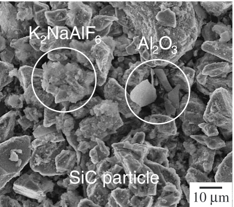
3.4.3 Recovered SiC particulate
Figure 6 shows the SEM photograph of the recovered SiC particles. Two kinds of materials adhered on the surface of the recovered SiC particles were observed, identified as Al2O3 and K2NaAlF6 by the X-ray diffraction analysis and
SEM-EDX. Al2O3was supposed to come from the oxide film
originally existed on the surface of the scraping waste and the oxidation of aluminum alloy during the treatment. It was considered that K2NaAlF6was produced by reacting the flux
with the aluminum alloy during the treatment:
(a)
(b)
10 mm
10 mm
10 mm
10 mm
Fig. 4 Appearance of recovered aluminum alloy (a) by the NaCl–50%KCl flux treatment, and (b) by the NaCl–45%KCl–10%KF flux treatment.
10
µ
m
10
µ
m
(a)
(b)
[image:3.595.149.448.72.204.2]Fig. 5 Microscopic photograph of cross section of aluminum alloy (a) before and (b) after flux treatment.
Table 2 Chemical composition of the aluminum alloy before and after the flux treatment.
Concentration,Ci/(mass%)
Before After
Si 10.3 10.4
Mg 0.32 0.26
Fe 0.40 0.42
[image:3.595.154.446.258.386.2] [image:3.595.45.292.454.533.2]KFðlin fluxÞ þNaClðlin fluxÞ
!KClðl in fluxÞ þNaFðlin fluxÞ ð3Þ
4KFðl in fluxÞ þ2NaFðl in fluxÞ þAlðlÞ !K2NaAlF6ðsÞ þ2Kðg orlin AlÞ
þNaðg orl in AlÞ ð4Þ
K2NaAlF6 could be eliminated from SiC particles by
leaching in NaOH solution and its reaction was represented as follows:
K2NaAlF6þ4OH
!2KþþNaþþ6Fþ ½Al(OH)
4 ð5Þ
However, an effective elimination method of Al2O3was not
found.
Because of the coexistence of Al2O3, the recovered SiC
particles cannot be reused as reinforcement. It is necessary to invent an appropriate elimination method of Al2O3or to find
the other uses.
3.4.4 Effect of the amount of KF addition
The effect of the amount of KF addition to the NaCl– 50%KCl flux on the form of recovered aluminum alloy and the recovery ratio of SiC was investigated. It was confirmed that at least 1 mass% of KF was required to recover the
aluminum alloy as a lump and to collect almost all of the SiC particles in the flux (see Fig. 7).
Figure 8 shows the effect of the amount of KF addition on K2NaAlF6content in recovered SiC particles. The amount of
K2NaAlF6 could be minimized with decreasing the amount
of KF addition.
3.4.5 Timing of the KF addition
From the above examinations, it was found that KF reacted with Al-alloy during the treatment. Then, minimization of the consumption of KF was considered. KF was initially mixed with the flux until now. Under the condition, most of KF had been consumed to the production of K2NaAlF6 during the
early melting and stirring stages.
As the next trial, KF was not mixed with the flux initially, but added just before the settling and separation. Figure 9 shows the effect of the timing of the KF addition on the appearance of the recovered Al-alloy. As mentioned before, when 0.5%KF was initially mixed with flux, Al-alloy was recovered as a granulated form [see Fig. 9(a)]. On the other hand, by adding KF later, the Al-alloy could be recovered as a lump even decreasing to 0.25%KF [see Fig. 9(b)]. There-fore, by adding KF later, the less amount of KF was enough to separate Al-alloy and SiC particle, and Al-alloy coalesces into a large mass. In addition, by decreasing the amount of
SiC particle
10
µ
m
K
2
NaAlF
6
Al
2
O
3
Fig. 6 SEM photograph of the surface of the recovered SiC particles.
10 mm
10 mm
10 mm
10 mm
(a)
(b)
Fig. 7 Appearance of recovered aluminum alloy (a) by the NaCl–49.75%KCl–0.5%KF flux treatment, and (b) by the NaCl–49.5%KCl– 1.0%KF flux treatment.
0
2
4
6
8
10
Amount of KF Addition, C
KF/ mass%
0
4
8
12
16
K
2NaAlF
6
Content,
C
K2
NaAlF
6
/ mass%
Fig. 8 Effect of the amount of KF addition to the flux on K2NaAlF6
[image:4.595.51.288.72.281.2] [image:4.595.317.535.80.247.2] [image:4.595.155.443.330.447.2]KF addition, the production of K2NaAlF6was also decreased
as was discussed in the previous section.
4. Concluding Remarks
The aluminum alloy and the SiC particulate can be recovered separately from the scraping waste of the Al–SiC composite material by using the flux of the NaCl–KCl–KF system. Only small amount of KF is enough to achieve a good result (KF<1mass%). The recovered aluminum alloy can be recycled for various usages. Because of the coex-istence of Al2O3and K2NaAlF6, the recovered SiC particles
cannot be reused as reinforcement. It is necessary to eliminate the contamination or to find the other uses. The recovered flux is reusable with supplemental addition of fluoride.
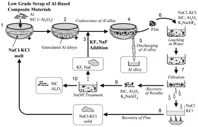
Recycling process flow was proposed based on the present result and is shown in Fig. 10.
(1) NaCl–KCl flux is melted, then, the scrap of composite material is charged into the flux melt.
(2) Al-alloys exist as a granulated form in the flux melt. (3) Fluoride is added into the Flux.
(4) Then, Al-alloy and flux are separated into two phases. (5) Al-alloy is discharged from the furnace and recovered. (6) On the other hand, the flux is leached in water. In the flux phase, these compounds shown in the figure co-exist.
(7) Because these compounds are not dissolved in water, by filtrating this solution, NaCl and KCl are separated as aqueous solution.
(8) By evaporating the water, NaCl and KCl are recovered and reused.
0.25% KF
10 mm
10 mm
10 mm
0.5% KF
0.5% KF
10 mm
10 mm
10 mm
(a) Initially Mixed
(b) Adding Later
10 mm
10 mm
10 mm
[image:5.595.81.521.69.242.2]Fig. 9 Appearance of recovered aluminum alloy after the treatment: (a) KF was initially mixed with the NaCl–50%KCl flux, and (b) KF was adding later into the flux.
[image:5.595.97.499.293.552.2](9) SiC, Al2O3 and K2NaAlF6 are leached in NaOH
solution.
(10) From the residue, SiC and Al2O3 are recovered, and
by evaporating the solution, KF and NaF are recov-ered. These fluorides can be reused as flux, because NaF has a almost equivalent ability to improve the wettability.
Acknowledgements
The authors are appreciated to AISIN TAKAOKA CO., LTD. for the financial support.
REFERENCES
1) Materials Science Society of Japan, ed.: Composite System in Materials, (Shokabo Publishing Co., Ltd., Tokyo, 2000), pp. 259–295. 2) H. Fukuda, R. Yokota and I. Shiota:Fukugou Zairyo Kisokougaku,
(Nikkan Kogyo Shinbunsya, Tokyo, 1994), pp. 12–201.
3) H. Fukuda: Fukugou Zairyo Nyumon, (Otsuki Syoten Publishers, Tokyo, 1986), pp. 1–177.
pp. 89–197.
5) Y. Nishida:An Encyclopedia of Metallic Material, (Sunchoh, Tokyo, 2000), pp. 886–894.
6) T. Ohnishi: J. Jpn. Inst. Light Met.46(1996) 525–532. 7) K. Oosumi: Shigen-to-Sozai113(1997) 982–985. 8) T. Nakamura: Materia Jpn.35(1996) 1290–1293. 9) F. Murata: J. Jpn. Inst. Light Met.46(1996) 551–556. 10) T. Ohnishi: J. Jpn. Inst. Light Met.46(1996) 557–563.
11) H. Sano, S. Kato, T. Motomura and T. Fujisawa:Yazawa Int. Symp. on Metallurgical and Materials Processing: Principles and Technologies, Vol. 1, (2003), pp. 1139–1145.
12) J. Lumsden: Thermodynamics of Molten Salt Mixtures, (Academic Press, London, 1966).
13) George J. Janz:Molten Salts Handbook, (Academic Press, New York, 1967).
14) R. R. Roy and T. A. Utigard: Metall. Mater. Trans. B29B(1998) 821– 827.
15) A. Silny and T. A. Utigard: J. Chem. Eng. Data41(1996) 1340–1345. 16) T. A. Utigard, K. Friesen, R. R. Roy, J. Lim, A. Silny and C. Dupuis:
JOM50(1998) 38–43.