Accuracy Analysis on the Automatic Registration of
Multi-Source Remote Sensing Images Based on the
Software of ERDAS Imagine
Debao Yuan1, Ximin Cui1, Yahui Qiu2, Xueyun Gu1, Li Zhang2
1College of Geoscience and Surveying Engineering, China University of Mining and Technology, Beijing, China 2The Geotechnical Institute of Beijing AeroSpace, Beijing, China
Email: [email protected]
Received January 31, 2013; revised March 1, 2013; accepted March 10, 2013
Copyright © 2013 Debao Yuan et al. This is an open access article distributed under the Creative Commons Attribution License,
which permits unrestricted use, distribution, and reproduction in any medium, provided the original work is properly cited.
ABSTRACT
The automatic registration of multi-source remote sensing images (RSI) is a research hotspot of remote sensing image preprocessing currently. A special automatic image registration module named the Image Autosync has been embedded into the ERDAS IMAGINE software of version 9.0 and above. The registration accuracies of the module verified for the remote sensing images obtained from different platforms or their different spatial resolution. Four tested registration experiments are discussed in this article to analyze the accuracy differences based on the remote sensing data which have different spatial resolution. The impact factors inducing the differences of registration accuracy are also analyzed.
Keywords: Multi-Source Remote Sensing Images; Automatic Registration; Image Autosync; Registration Accuracy
1. Introduction
With the development of remote sensing technology, more and more remote sensing images are being pro- duced. These images are obtained in different time phases, resolutions, wave range and by different sensors. The remote sensing and artificial intelligent technologies make the fusing and comprehensive utilization of differ- ent-source remote sensing images possible. Nevertheless, one of the key problems is how to realize the images match automatically. Some institutions and scholars, in China and abroad, have made abundant research on re- mote sensing image automatic registration. Some re- searchers created the relevant algorithm on different types of data design. In 1998, Zuxun Zhang et al. put forward a rapid full-automatic method for the registration of remote sensing images with different resolutions and from different sensors. The main content of the method in this article is to use multi-stage image probability re-laxation integrated matching technology. The high reso-lution image was taken as a reference image, and the reporter also makes full use of high-resolution-image in- formation to improve the accuracy of registration. How-ever, this method requires the spectral characteristics of the selected images shouldn’t be in much difference. Le Yu et al. [1] adopted the coarse-to-fine method to register
the remote sensing images. The method is described here. Firstly, the Sift operator was used to extract feature points of images for coarse registration. Secondly, the method of adaptive-feature extraction based on Harris operator was then adopted to make the feature points distribute uniformity. Finally, the TIN etc., multiple technologies were used to realize the image fine registra-tion [2,3]. However, this method is directly based on the maximum residual information when making the coarse deletion. The method of deleting coarse has been proven not robust sufficiently. The ERDAS IMAGINE software has also been made research in multi-source remote sensing image registration. In version 9.0 and above ver- sion, an extra special remote sensing Image automatic registration module—Image Autosync module, was added in. This module could realize the automatic registration of the multi-source remote sensing images. The registra- tion efficiency and accuracy are greatly improved. Nev- ertheless, in this module, the accuracy of remote sensing image registration is different for images with different resolution and in different platforms. The lower the re- solution, the lower the registration accuracy is.
the previous research. The Image Autosync module of Image Autosync is validated in the registration of remote sensing data although there are still some multiple prob- lems in Accuracy differences. The brief analysis of the causes of problems is given.
2. Multi-Source Remote Sensing Image
Registration
Multi-source remote sensing image registration is su- perimposing [4] of two or more remote sensing images which have different wave band, different time phase, different angles of view or different sensor within the same area or the same target. The main purpose of image registration is to achieve two or more remote sensing images with the geometric position consistency through decreasing or eliminating the geometric deformation caused by the imaging-condition differences between pre- registration images and the reference images. Multi- source remote sensing image automatic registration is a key step of remote sensing image preprocessing, and is also the basis to realize remote sensing image analysis of the same target or area, comprehensive and comparative processing. It plays a quite important role in processing the remote sensing image.
3. Image Autosync Module
Image Autosync is an added module in the ERDAS IMAGINE 9.0, which provides an automatic image reg- istration tools to ensure the users in various technical levels to complete professional registration work easily. The module mainly includes image edge matching and geographic reference image registration functions. The first workflow is to input two or more images with po- tential difference, such as HJ images and TM images. Thousands of homonymy points in their overlap region are produced to obtain high-precision registration of re- mote sensing image. This method can not only change the existed registration accuracy in the geographic- reference image, but also realize rapid registration from the original image to image based on geographic refer- ence. The second workflow is the edge matching, which apply the partial model to the overlap part of the image. This submodule Autosync Workstation in the Image Autosync module is mainly used to complete registration of remote sensing image with different sensors, different time phases, different resolutions, and make a detailed contrastive analysis with their registration accuracy.
3.1. Autosync Workstation
Automatic-Registration Theory
In the ERDAS IMAGINE 9.0 and above versions, the automatic-registration module with the tool APM (Auto- matic Point Measurement) to automatically match the
control point. In Image Autosync, APM is a software tool to automatically identify the control points consistent when input two different grid images—input image and the reference image. The basic theory of APM automati- cally matching the control point is that use pyramid data structure to match level by level. When APM began to run, firstly, it establishes respectively a 3 × 3 image pyramid data structure for the input image and the refer- ence image, which is a group of image sequence gener- ated from low to high resolution. Began to match with the lowest level resolution, the APM will then find the matching point and mapping it to the search area of the last layer, and improve a layer of resolution of the two images, match in the search area, improve the resolution until in accordance with the original image resolution. The matching points of the two images are obtained [5].
3.2. Autosync Workstation Registration Process
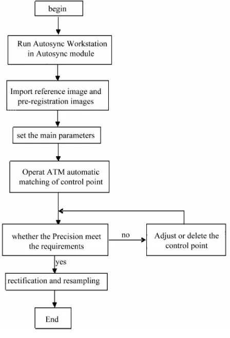
It’s very convenient for ERDAS IMAGINE to realize the automatic registration. The user only need to input the pre-registration IMAGE and the reference IMAGE, and choose feature points extracted options, IMAGE cor- rected option and IMAGE resampling options in different options, and finally we can get the images which splice of reference IMAGE after registration and pre-registra- tion IMAGE. The concrete realization steps as shown in Figure 1.
Under the working environment of Autosync Work- station, a reference image and one or more pre-registra- tion images are needed to be input. In order to achieve higher registration accuracy, the overlap of the images should be at least 20% [6]. As the reference image and pre-registration images sometimes come from different sensors, different time phases and different resolutions, the shear in advance may needs, so that the two images could be overlapped more.
Figure 1. Registration process.
smaller in mountainous area of the image or when image quality is poor [7].
3.3. Accuracy Control and Resampling
Image registration accuracy is usually measured by RMS error (root mean square). The following is calculation formula:
2
2Y Y
RMS X X (1)
X and Y represents the original coordinates in Formula (1), and X and Y represents coordinates after con-
version. The total RMS error is determined by the resid- ual. Residual is the distance between the original coordi- nate and inverse transform coordinates on one direction. Residual X is the distance between original X coordinates and conversion X coordinates, so as residual Y, total RMS error shows as follow:
2 2 1 1 1 n n i i i i G YG
n n
1
T
X (2)In Formula (2), T represents total RMS error, n repre- sents the number of GCP point, XGi represents the X re- sidual of GCPi, YGirepresents the Y residual of GCPi.
Through the GCP tools in Autosync Workstation, the RMS error and total RMS error of GCP points can be seen. If the RMS error doesn’t reach the requirements of precision, (some) low quality control points will be de- leted to reach the accuracy [8].
After the RMS reached the accuracy, the pre-registra- tion image will be matched and sampled. Due to more points extracted automatically, usually, the Polynomial (Polynomial transformation) is used to realize registra- tion. In this paper, three Polynomial transformations were chosen [9]. In the resampling, bilinear interpolation method is selected. The combination of the above two transformation mode can not only reach the registration accuracy requirement also can improve the speed of reg- istration. After the resampling, we can analyze the stabil- ity of ERDAS IMAGINE automatic registration for multi-source remote sensing data registration through the local amplification of prominent feature and total RMS [10].
4. Image Autosync Registration Test
In order to analyze the impact factors to precision for the multi-source sensor image registration, the data and the way of combinations in the test are as follows: 30 m resolution, HJ data of Jiangsu and HJ data; 30 m resolu- tion, TM data of Tibet and TM data; 30 m resolution, HJ data of Jiangsu and TM data and 0.41 m resolution Geo- eye data of Hainan area and 0.1 m resolution unmanned aerial vehicle (uav) data. This paper uses the above data to realize the automatic Image registration through the ERDAS IMAGINE, and analyze the accuracy of regis- tration results from the vision and the root mean square.
4.1. Automatic Registration Test
In the four tests, the cubic polynomial is used for regis- tration and the method of bilinear interpolation is used for image resampling.
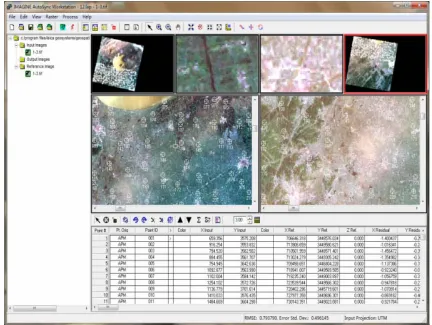
Test 1: HJ data and HJ data registration test Loading data and automaticlly extracting rear interface of control point which is shown in Figure 2.
Accuracy analysis
Some typical points were selected from the report of ERDAS automatic registration, shown in Table 1. This table includes the minimum and the maximum error of the registration points and maximum matched and mini- mum matched point.
1) Visual effect analysis. As shown in Figure 3, it is the local enlarged view after two HJ star image spliced.
2) The RMS error analysis. From self-generated re- port of ERDAS, the root mean square error is 1.182 after HJ star image registration.
Figure 2. HJ automatically extract feature point.
[image:4.595.99.497.425.723.2]Table 1. Environment star image registration.
Point ID X Input Y Input X Ref Y Ref X Residual Y Residual Error Match
0170 13460.451 2195.385 790342.177 3414217.719 2.2019 1.2808 2.547 0.86
0618 1765.198 6210.755 439195.634 3293807.475 −0.2925 0.0585 0.298 0.93
1076 4739.070 9743.559 527912.958 3187954.892 0.8373 1.2257 1.482 0.98
0454 8755.150 4974.081 648934.394 3330851.733 0.8600 −1.0767 1.378 0.85
extraction is shown in Figure 4. Accuracy analysis
Select some typical points from the report of ERDAS automatic registration, shown in Table 2. This table in- cludes the minimum error and the maximum error of the registration points and maximum matched and minimum matched point.
1) Visual effect analysis. As shown in Figure 5, it is the local enlarged view of linear features joint selected after two TM images spliced.
2) The RMS error analysis. From self-generated re- port of ERDAS, the root mean square error is 0.183 after TM image registration.
Test 3: HJ data and TM data test
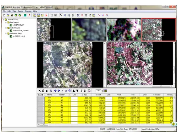
The reference image we selected is HJ data of 30 m resolution the in the test, and pre-registration image is TM image of 30 m resolution. The test data loading and feature points extracting is shown in Figure 6.
1) Visual effect analysis. As shown in Figure 7, it is the local enlarged view of linear features joint selected after TM and HJ images spliced.
2) The RMS error analysis. From self-generated re- port of ERDAS, the root mean square error is 4.499 after TM and HJ image registration.
Test 4: Geoeye and unmanned aerial vehicle (UAV) data
This test used two images with different sensors and different resolution to test. The test data were Geoeye data of 0.41m resolution and UAV image of 0.1 m reso- lution. The test data loading and feature point distribution is shown in Figure 8.
Accuracy analysis
Select some typical points from the report of ERDAS automatic registration, shown in Table 3. This table in- cludes the minimum error and the maximum error of the registration points and maximum matched and minimum matched point.
1) Visual effect analysis, as shown in Figure 9, it is the partial enlarged view of linear features joint selected after Geoeye and uav images spliced.
2) The RMS error analysis, from self-generated report of ERDAS, the root mean square error is 14.396 after Geoeye and uav images registration.
4.2. Results of Test
From the tests above we can find that for different im- ages, the registration accuracy of image Autosync auto- matic registration module is quite different. For image of the same sensor and resolution, the registration precision is higher and lower for image of different sensors and resolutions. For image of different platforms and resolu- tions, after registration, the accuracy is worst. The de- tailed comparison is shown in Table 4.
5. Conclusions
The conclusion can be obtained from the analysis, by using Image Autosync to register multi-source remote sensing Image and through analyzing the registration precision and registration efficiency of each experiment (this paper does not involve the time), that automatic registration accuracy of homologous data is the highest, registration accuracy of different source but the same resolution image take second place, and registration ac- curacy of different source different resolution image is the worst. The reasons for the differences of registration precision mainly include the following:
1) The quality of image affects the registration accu- racy directly. The HJ image and TM image are both 30 m resolution, but their respective registration accuracy is discriminating, this mainly because imaging quality of the TM images is better.
2) The registration accuracy of the same sensor images is higher than different sensor precision, which is mainly caused by imaging time and point of view with the dif- ferent sensors. Even if the same target in different sensor image can also present inconformity scales. Image Auto- sync realizes automatic registration only once, if realizes the thoughts of secondary registration from coarse to refined, it will improve their registration accuracy as to the registration of different source remote sensing data.
Figure 4. TM automatically extract feature points.
Table 2. TM image registration.
Point ID X Input Y Input X Ref Y Ref X Residual Y Residual Error Match
0921 762.893 8182.871 389711.396 3789837.392 0.1389 −0.0412 0.144 0.95
1071 6525.201 9179.280 562593.925 3759741.767 −0.8837 −0.1380 0.894 0.91
702 1349.308 6233.846 407356.245 3848286.181 −0.2781 0.1009 0.242 0.98
1004 8551.452 8543.257 623398.652 3778732.473 −0.9855 −0.3103 1.033 0.90
Figure 6. TM and HJ automatically extract feature.
Figure 7. Local enlarged view points and its distribution.
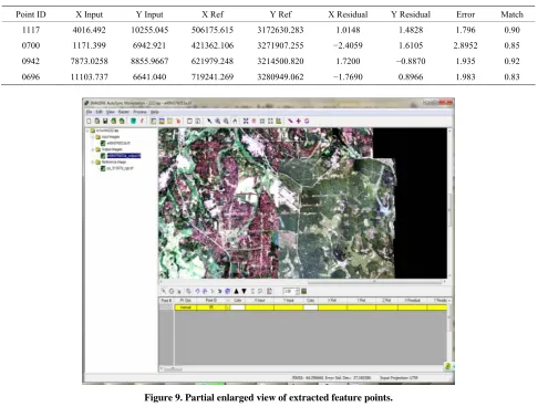
[image:7.595.146.450.494.722.2]Table 3. Geoeye and uav image registration.
Point ID X Input Y Input X Ref Y Ref X Residual Y Residual Error Match
1117 4016.492 10255.045 506175.615 3172630.283 1.0148 1.4828 1.796 0.90
0700 1171.399 6942.921 421362.106 3271907.255 −2.4059 1.6105 2.8952 0.85
0942 7873.0258 8855.9667 621979.248 3214500.820 1.7200 −0.8870 1.935 0.92
0696 11103.737 6641.040 719241.269 3280949.062 −1.7690 0.8966 1.983 0.83
[image:8.595.57.539.489.518.2]Figure 9. Partial enlarged view of extracted feature points.
Table 4. Automatic-registration-accuracy comparison of multi-source remote sensing data.
Registration Image TM and TM Image HJ and HJ Image HJ and TM Image Geoeye and UAV Image
RMS Error 0.183 1.182 4.499 14.396
registration precision.
6. Acknowledgements
This study is financially supported by National Natural Science Foundation of China (41071328); National key basic research development planning (973) project (2007 CB209400). The ministry of education in the new cen- tury talents support plan funded projects (NECT-07- 07098); Mining spatial information technology state bu- reau of surveying and mapping key laboratory open fund project (KLM200816).
REFERENCES
[1] L. Yu, D. R. Zhang and E. J. Holden, “A Fast and Fully Automatic Registration Approach Based on Point Fea- tures for Multi-source Remote-Sensing Images,” Com-
puters & Geosciences, Vol. 34, No. 7, 2008, pp. 838-848.
doi:10.1016/j.cageo.2007.10.005
[2] J. W. Wu and Y. P. Qin, “The Influencing Factors Analy- sis of Multi-Source Remote Sensing Image Polynomial Registration Accuracy,” Computer Engineering and Ap- plications, Vol. 45, No. 32, 2009, pp. 153-155.
[3] L. G. Wan and Y. L. Shi, “The Rapid Image Registration Based on AutoSync,” Surveying and Mapping, Vol. 33, No. 3, 2010, pp. 103-106.
[4] G. S. Li, J. X. Zhang and W. D. Song, “The Automatic Extraction of Control Points in Remote Sensing Image Registration,” Journal of Liaoning Engineering Technol- ogy University, Vol. 24, No. 1, 2005, pp. 41-44.
[5] A. D. Ventura, A. Rampini and R. Schettini, “Image Reg- istration by Recognition of Corresponding Structures,”
IEEE Transactions on Geo-Science and Remote Sensing, Vol. 28, No. 3, 1990, pp. 330-334.
Registration Based on ERDAS IMAGINE 9.1,” Xinjiang Environmental Protection, Vol. 32, No. 1, 2010, pp. 27- 29.
[7] S. L. Zhu, B. S. Zhu, G. W. Wang, et al., “The Processing
Principle and Application of Remote Sensing Image,” Science Press, Beijing, 2006.
[8] S. T. Liu and S. Q. Yang, “Research Progress of Image Registration Technique,” Lighting and Control, Vol. 14,
No. 6, 2007, pp. 99-105.
[9] Z. X. Zhang, J. Q. Zhang, M. S. Liao, et al., “The High
Precision Automatic Registration of Remote Sensing Im- age,” Wuhan: Wuhan Technical University of Surveying and Mapping, Vol. 23, No. 4, 1998, pp. 4-8.