th
Avionics-Based GNSS Integrity Augmentation
Performance in a Jamming Environment
Roberto Sabatini1, Terry Moore2, Chris Hill2and Subramanian Ramasamy1
1
School of Aerospace, Mechanical and Manufacturing Engineering RMIT University, Melbourne, VIC 3000, Australia
2
Nottingham Geospatial Institute University of Nottingham, NG7 2TU, UK
Abstract
Intentional and unintentional radiofrequency interference (i.e., jamming) can result in degraded navigation accuracy or complete loss of the GNSS signal tracking. Jammers can be classified into three broad categories: Narrowband Jammers (NBJ), Spread Spectrum Jammers (SSJ) and Wideband Gaussian Jammers (WGJ). In recent years, a number of effective jamming detection and anti-jamming (filtering and suppression) techniques have been developed for military GNSS applications and some of them are envisaged to be used for civil purposes (e.g., terrorist attacks). The synergies between these jamming detection techniques and our newly developed Avionics-Based Integrity Augmentation (ABIA) system are investigated in this paper. In particular, GNSS vulnerability to NBJ, SSJ and WGJ types of jamming is analytically described in terms of Jamming to Signal (J/S) tracking thresholds and the models for calculating the minimum acceptable aircraft-to-jammer ranges are presented. Simulation results demonstrate that the proposed ABIA architecture is capable of performing jamming detection and avoidance when GNSS is considered as the primary source of navigation data.
Keywords: Global Navigation Satellite System, Jamming, Air Navigation, Integrity Augmentation and Trajectory Optimisation.
Introduction
Typically, GNSS signals reach the airborne receivers at very low power, and radiofrequency interference can be the result of a number of potential sources including:
Unintentional interference in the operating frequency band.
Intentional jamming (e.g., premeditated GNSS signal attack including terrorist activities and electronic warfare).
High-power signals in the adjacent frequency bands. Denial of service and scheduled outages.
Natural interference including solar flares.
th
Positioning System (GPS) signals, the L1 C/A signal received from the 25 W transmitter with a 13 dBiC antenna at a range of 12, 550 miles is in the order of -150 dBW. The impact caused by jamming on GNSS detection capability has been studied and analytically described [1, 2]. Though a number of effective jamming detection and anti-jamming (filtering and suppression) techniques have been developed in the last two decades for military applications, only a few methods are available for civil use [3, 4]. A number of systems have been designed and implemented to detect jamming such as Jammer Detection and LOCation System (JLOC) in the US and GNSS Availability, Accuracy, Reliability and Integrity Assessment for timing and Navigation system (GAARDIAN) in UK. Jammers are classified into three broad categories: Narrowband Jammers (NBJ), Spread Spectrum Jammers (SSJ) and Wideband Gaussian Jammers (WGJ). Typical jamming signals can be classified into four classes:
Class I: continuous wave signal.
Class II: chirp signal with one saw-tooth function. Class III: chirp signal with multi saw-tooth functions. Class IV: chirp signal with frequency bursts.
In the majority of cases, jamming signals are transmitted in the L1/E1 band, which are used in receivers for civilian applications. These signals can affect all GNSS signals including GPS, Galileo, GLObalnaya NAvigatsionnaya Sputnikovaya Sistema (GLONASS), BeiDou
(Compass), Indian Regional Navigational Satellite System (IRNSS) and Quasi-Zenith Satellite System (QZSS).
ABIA System
th
[image:3.595.174.424.136.303.2]case of predicted/ascertained GNSS data losses or unacceptable signal degradations exceeding the Required Navigation Performance (RNP) specified for each phase of flight. Additionally, it provides information to the on-board pilot in a manned aircraft or to the RPAS pilot in the Ground Control Station (GCS) to avoid further data losses/degradations.
Fig. 1: ABIA system architecture. Adapted from [8].
The IFG module generates the Caution Integrity Flag (CIF) and Warning Integrity Flag (WIF) alerts. The CIF is a predictive annunciation that the GNSS data delivered to the avionics system is going to exceed the RNP thresholds specified for the current and planned flight operational tasks (GNSS alert status), while the WIF is a reactive annunciation that the GNSS data delivered to the avionics system has exceeded the RNP thresholds specified for the current flight operational task (GNSS fault status). The Time-to-Caution (TTC) is defined as the minimum time allowed for the caution flag to be provided to the user before the onset of a GNSS fault resulting in an unsafe condition and Time-to-Warning (TTW) is the maximum time allowed from the moment a GNSS fault resulting in an unsafe condition is detected to the moment that the ABIA system provides a warning flag to the user.
ABIA Integrity Flags for Jamming
The main causes of GNSS data degradation or signal losses in aviation applications are analytically modeled in [5, 6]. The threshold limits required for the IFG to produce caution and warning flags are identified in [7]. The thresholds are set based on the aircraft-satellite relative geometry including estimated Horizontal and Vertical Position Error (HPE/VPE), radio frequency elements and receiver tracking loops. The Scalar Tracking Loops (STL) typically employs Delay Lock Loops (DLL) to track the code phase and Phase Lock Loops (PLL) or Frequency Lock Loops (FLL) to track the carrier phase. Current state-of-the-art STL also employ combined PLL and FLL for carrier tracking to obtain better results in navigation position accuracy and to enhance tracking [5-8]. Currently, Vector Tracking Loops (VTL) are also employed, which are based on advanced receiver architectures capable of tracking signals in a combined manner [9]. VTL provide the advantages of operating at a lower total carrier power to noise ratio (C/N0) and in higher dynamics environments when compare with STL
th
based on C/N0, as well as the applicable radiofrequency interference. In general, the effects of
GNSS signal jamming are:
Jamming affects the GNSS receiver’sܥ/ܰ. Signal-to-noise ratio (S/N) decreases.
Jamming contributes to multipath effects of GNSS signals in dense urban areas. When jamming exists, GNSS receivers might react differently from the ideal case. The relationship between effective carrier-to-noise ratio (C/N) and jammer signal power (J) is given by [10]:
ே = [ܥ/ܰ]/ቈ1 +
ቀಿ బቁቀೄቁ
ோ (1)
whereܰis the thermal noise power spectral density, ܴܿis the P-code chipping rate, Sis the signal power received at the GNSS antenna input, C is the carrier power and J/S is the jamming-to-signal ratio. In the general method, range to the jammer, atmospheric losses, and a corresponding noise in the jammer are computed, all as a function of time along the trajectory. Jamming is modelled based on the J/S levels. The J/S performance of a GNSS receiver at its tracking threshold can be evaluated by the following equation [11]:
ௌ= 10 logܴܳቈ1/10
.ଵቀಿ బቁ
ಾ ಿ − 1/10.ଵቀ
ಿ బቁ (2)
where ܳ is the processing gain adjustment factor and is equal to 1 for Narrowband Jammers (NBJ), 1.5 for Spread Spectrum Jammers (SSJ) and 2 for Wideband Gaussian Jammers (WGJ), ܴ is the code chipping rate (chips/s) and (ܥ/ܰ)ெ ூே is the receiver tracking threshold (dB-Hz). Since the weak limit in an avionics receiver is the carrier tracking loop threshold, this threshold is usually substituted for (ܥ/ܰ)ெ ூே. During the flight test activities performed on TORNADO-IDS with unaided C/A code avionics receivers, it was found that in all dynamics conditions explored and in the absence of jamming, a (ܥ/ܰ) of 25 dB-Hz was sufficient to keep tracking the satellites. As an example, using this 25 dB-Hz tracking threshold, we can calculate the J/S performance of the TORNDO-IDS GPS receiver considering one of the satellites tracked during the descent and during this manoeuvre, the C/N0 for Pseudo Random Noise (PRN) PRN-14 was about 37 dB-Hz. Table 1 shows the
corresponding J/S calculations, assuming(ܥ/ܰ)ெ ூே = 25 dB-Hz.
Table 1: J/S calculations for 25 dB-Hz tracking threshold
Jamming Q ܴ (ܥ/ܰ)௧௦ௗ (ܥ/ܰ) J/S NBJ 1 1.023*10 25 dB-Hz 37 34.82
SSJ 1.5 1.023*10 25 dB-Hz 37 36.58 WGJ 2 1.023*10 25 dB-Hz 37 37.83
The transmitted power of the jammer and its distance with respect to the GNSS receiver required for jamming is expressed in terms of Effective Radiated Power (ERP). Using these J/S values, the minimum range in metres from a jamming source can be calculated from:
ܴ =ସగఒೕ10
ಶೃುೕషುೝೕశಸೝೕషಽೝ
మబ ) (3)
where ܧܴܲ௧is the effective radiated power of the jammer (dBw), j is the wavelength of jammer frequency (m),ܲis the received (incident) jamming power level at threshold = J/S +
th
antenna gain towards the jammer (dBiC) and ܮ is the jammer power attenuation due to recover front-end filtering (dB). The PLL, FLL and DLL error models described in [6] allow determining the C/N corresponding to the receiver tracking thresholds. The integrity flag criterion applicable to the ABIA system is [7, 8]:
ቀே ቁ
்௦ௗ= ݉ ܽݔቀ
ேቁ,ቀ
ேቁி,ቀ
ேቁ,ቀ
ேቁାி,ቀ
ேቁ்൨ (4)
where (C/N) is the minimum C/N for PLL tracking, (C/N)is the minimum C/N for FLL tracking, (C/N)ୈis the minimum C/N for DLL tracking, (C/N)ାis the minimumC/Nfor combined PLL and FLL tracking and (C/N)is the minimumC/Nfor VTL based tracking. In general, when the PLL loop order is made higher, there is an improvement in dynamic stress performance. Therefore, third order PLL are widely adopted in avionics GNSS receivers. Assuming 15 to 18 Hz noise bandwidth and 5 to 20 msec pre detection integration time (typical values for avionics receivers), the tracking threshold for the PLL gives 25 to 28 dB-Hz. The main error associated with a GNSS receiver FLL are the dynamics stress error and frequency jitter caused due to thermal noise. The receiver tracking threshold is adopted such that the 3-sigma jitter must not exceed one-fourth of the frequency pull-in range of the FLL discriminator. Using theoretical and experimental threshold values, the receiver J/S performance for the various cases of practical interest are calculated. When available, flight test data collected in representative portions of the aircraft operational flight envelope shall be used. The criteria for generating CIF and WIF based on J/N ratio is described in earlier research [5-7, 11-12]. Considering an additional 5% margin on the 3-sigma tracking thresholds for the CIF, the following detailed criteria are introduced for the ABIA integrity thresholds:
When either 42.25° ≤ 3σ≤ 45°or0.2375T ≤ 3σ≤ 0.25Tor0.05d ≤
3σୈ ≤ d,the CIF shall be generated.
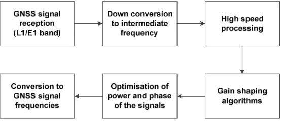
When either3σ> 45°or3σ> 1/4ܶor3σୈ >݀,the WIF shall be generated. The processing of GNSS signals in a receiver specific to anti-jamming function is illustrated in Fig. 2. Interference detection is typically performed based on a number of receiver parameters including output power, variance and standard deviation of the output power (correlated), carrier phase uncertainty and Automatic Gain Control (AGC) values. The key component to detect interference in the received signal is the Automatic Gain Control (AGC). In order to minimize the signal loss, the amplitude of the received GNSS signal is tuned to the ADC range. The gain in AGC drops significantly when there is an increased power in the GNSS bandwidth. The chirp signals are predominantly used for jamming in the recent times. Chirp signals are typically sinusoidal or cosine signals with sweeping of frequency within in-band GNSS frequency ranges. The chirp signals are modelled using a periodic Frequency Modulated (FM) signal and can be expressed as [12, 13]:
ݔ(ݐ) = a sin(2ߨ∑ୀஶ (∫௧݂ଵ(ݐᇱ− ℎ.ܶ௦,ଵ).݀ݐᇱ+ ⋯ + ∫௧݂(ݐᇱ−ℎ.ܶ௦,).݀ݐᇱ)) (5) where ݂ଵ(ݐᇱ− ℎ.ܶ௦,ଵ)is the 1st saw tooth function, ݂(ݐᇱ− ℎ.ܶ௦,)is the nth saw tooth function, ܶ௦, is the sweep time. A number of algorithms have been proposed for jamming detection, localisation and characterisation of interfering signals. Considering a GNSS jammer transmitting chirp signals (with zero mean) from a random position, the received signal can be expressed as:
ݏ(ݐ) =ݏ௧(ݐ)ට(.ସగ.ௗ )ఈ.݁ଶగௗ/ (6)
th
[image:6.595.160.439.176.298.2]are being introduced. These signals inherently possess higher precision of orientation and anti-jamming performance, and are also compatible existing GNSS signals. Binary Offset Carrier (BOC) modulation is introduced to increase the ERP for anti-jamming performance without affecting the existing GNSS signals. In these cases, Costas loop is used as carrier tracking loop to receive BOC modulated signals. When a jamming signal interferes with the GNSS signal, phase measurement error increases beyond a specified threshold value and as a consequence the tracking loop loses lock.
Fig. 2: GNSS receiver processing for anti-jamming function
The design of the GNSS antenna generally provides a superior polarisation signal reception and poor low elevation angle gain. As a result of superior polarisation, cross polarisation reception is less than -10dBic and thus effectively reduces unwanted signal reflections. In order to design GNSS receivers against interference, bandwidth, sampling and hardware considerations are taken into account. In order to increase the accuracy of the signal, narrow correlator spacing is employed by sharpening up the auto correlation function. Therefore, it is ensured that the correlators are still operating in a linear range. Noise increases due to the increase in pre-correlation bandwidth but it can effectively tackled by employing superior digital signal processing algorithms. Generally, the signal processor adopted has the capability of performing code correlation in two different modes: an early-minus-late power mode and a dot-product mode. The signal processor has two correlators in each channel and can operate one of the correlators as an early or an early-minus-late correlator. The normalised dot-product discriminator is given by [14]:
݀߬= ூషூುାொషொು
ூುమାொುమ (7)
where I and Q values are summed over the Prediction Integration Interval (PDI). ܫିூand
ܳିூrepresent the I and Q values when the hardware in implemented in the dot-product mode. P stands for I and Q and are similar to the ones used in carrier loop discriminators. For an infinite pre-correlation bandwidth, the normalised Early-minus-Late (EL) discriminator has an output at high values of SNR and the estimation is given by:
ܧ(݀߬) =(ଶିௗ)ସ(ଶିௗ)ఛమାସఛమ chips, -d/2≤ ߬≤ d/2 (8)
where ߬is the tracking error and ݀ is the EL discriminator spacing in chips. The standard deviation of the pseudorange observations (ߪఛ) is estimated from the discriminator output standard deviation (ߪௗ)and is given by:
ߪఛ= √ଶ்ீ ߪௗ (9)
th
receiver is operating on or near the correlation peak. The code-correlation process of the receiver is designed to increase the signal strength when compared to that of inherent and added noise. The spread spectrum processing gain (ܩ) is defined as the ratio of the spread bandwidth to the unspread (baseband) bandwidth and is expressed in dB. The post-correlation
ܵ/ܰ is given as:
(ܵ/ܰ)௦௧ି.= (ܵ/ܰ)ି.+ܩ (10)
When the receiver code is aligned with the transmitted code, the signal power at the band pass output is crushed into approximately 100 Hz of bandwidth. The processing gain can be calculated from:
ܩ = 10݈݃ ቀଶ்ವೃቁ[݀ܤ] (11)
whereܥோ is the chipping rate andܶ is the data period. For the C/A code this works out to be about 43 dB. Typical avionics receivers have a cut off value at 10 dB, which means that if the value is less than this the satellite signal level is too low to be used in the positioning computations [14]. An additional threshold criterion to be accounted for in the ABIA system is given as:
ܵ/ܰ௦௧ି.= ܵ/ܰି.+ܩ³10݀ܤ (12)
Whenܩis more than 11 dB (margin of 1 dB), the CIF shall be generated. Whenܩis less than 9 dB (margin of 1 dB), the WIF shall be generated.
Avoidance of Jamming Environment
A number of jamming mitigation techniques are normally adopted as counteract measures. The adoption of filters to fade out the jamming signal is usually employed. Specifically, a notch filter (narrowband band stop filter) is used against continuous wave or narrowband electronic attacks. Selective Availability Anti-Spoofing Modules (SAASM) are employed by the US DoD for tackling spoofing of GNSS signals. Controlled Radiation Pattern Antenna (CPRA) offering null steering is often bulky and expensive. Multi-constellation / multi-frequency receivers including the ones using embedded Software Defined Radio (SDR) based processing are used for tackling jamming. An analysis of the identified degradation results in inferring that a common criterion based on satellite elevation variation in the body frame can be adopted. Depending upon the technique used to capture the jammer’s coordinates, the targeting error represents approximately half of the final Circular Error Probable (CEP). Earlier methods to overcome jamming adopted the integration of GNSS with other navigation sensors; say Inertial Navigation System (INS) sensors [10]. When it is detected that the tracking loop (PLL/FLL/DLL/VTL) has lost lock in a jamming environment, the GNSS signal is decoupled from the integrated navigation system and then guidance for avoidance trajectory is obtained from the calibrated INS operating in a coast mode. Generally, in a tightly coupled architecture, the GNSS data is used to aid the navigation solution, and the INS is used to remove the majority of the error from the signal input to the GPS tracking loops. The amount of Doppler error that can be removed is determined from the accuracy of the navigation solution, and further, by the dynamics of the manned aircraft/RPAS. If the integrated navigation solution is more accurate, then the error is drastically reduced and the receiver loop bandwidth is reduced leading to the susceptibility to jammer noise. The GPS carrier tracking loop is more susceptible to jamming due to the small wavelength of the carrier (0.19 metres) compared to the P-code chip width (29.3 meters). One method of detecting carrier loop lock is to monitor the detected phase error estimate (u) in the PLL and is expressed as [10]:
th
The threshold of the loop is dynamically altered according to the computed S/N ratio and it is assumed that a loss of lock is evident when the signal strength falls below a fixed threshold. In order to compute the signal generated for input to the tracking loops, noise due to bot thermal and jammer sources is superimposed on the signals. Noise is generally assumed to be Gaussian in nature and its power is obtained from C/N value and the noise power is given by:
Noise power=ܲௌܤ/(C/N) (14) whereܲௌis the recived satellite signal power andܤis the prediction bandwidth. The design of avoiding jamming environment by adopting ABIA system involves the evaluation of the overall avoidance volume. The overall avoidance volume is obtained by combining the avoidance volume resulting from the jammer and uncertainty volume resulting from positional deviations. Extended Kalman Filter (EKF), Unscented Kalman Filter (UKF) or particle filter is used for multi-sensor data fusion of different navigation sensors to obtain the Position, Velocity and Attitude (PVA) estimates. Pseudo-spectral optimisation (PSO) or constrained Differential Geometric Optimization (DGO) techniques are used to generate the new trajectory based on the available time to conflict (host manned aircraft/RPAS entering the jamming avoidance volume). The shape of the combined jamming avoidance volume and navigation errors is described using spherical harmonics. Depending on if the errors are statistically independent or dependent; the resultant volume is obtained for uncorrelated or correlated errors respectively [16-19]. The selection of the optimal trajectory from the generated set of safe trajectories is based on minimisation of the following cost function:
ܬ= ݓ௧∙ tௌிா+ݓ∫[ܵܨܥ∙ܶ(ݐ)]݀ݐ− wௗ∙ܦ −ݓௗ∙ ∫ܦ(ݐ)݀ݐ (15)
where ܦ(ݐ) is the estimated distance of the generated avoidance trajectory points from the avoidance volume associated with the obstacle,ܦ = ݉ ݅݊[ܦ(ݐ)]is the estimated minimum distance of the avoidance trajectory from the avoidance volume,ݐௌிா =ݐ| is the time at
which the safe avoidance condition is successfully attained, ܵܨܥ[
ே ∙ݏ] is the specific fuel consumption, ܶ(ݐ) is the thrust profile, and ݓ௧,ݓ,ݓௗ,ݓௗ are the weightings attributed to time, fuel, distance and integral distance respectively. In time-critical avoidance applications (i.e., closing-up on jamming environments at high relative velocities especially for military aircraft) appropriate higher weightings are used for the time and distance cost elements. Based on the criteria identified for integrity monitoring and augmentation, the jamming environment represented by the radiation pattern is avoided by initiating avoidance manoeuvres obtained from the FPOM. In order to constrain the trajectory optimization process, dynamic constraint criteria are adopted.
Simulation Cases
th
(main lobe in the case of directional jammer). The optimised avoidance trajectory obtained in the presence of directional and non-directional jammers is illustrated in Fig. 5 and 6 respectively.
Directional Jammer Main Lobe
Aircraft Trajectory Position
Uncertainty
Side Lobes
Fig.5: Optimised avoidance trajectory in the presence of directional jammer
Non-directional Jammer
Aircraft Trajectory Position
Uncertainty
Fig.6: Optimised avoidance trajectory in the presence of non-directional jammer
th
Fig.7: Trajectory in the presence of directional jammer
Conclusion
In this research the effects of jamming on GNSS integrity augmentation performance were examined. The analytical models of Jamming-to-Signal (J/S) tracking thresholds for different types of jamming were described. In particular, the models for calculating the minimum acceptable aircraft-to-jammer ranges and the determination of the overall avoidance volume were presented. Simulation case studies conducted in the presence of directional and non-directional jammers demonstrated the capability of the on-board ABIA system to avoid jamming. Further research is focussing on the ABIA evolutions for Next Generation Flight Management System (NG-FMS) applications [20-23] as well as trajectory optimization for future CNS+A systems and 4 Dimensional Trajectory (4DT) Intent Based Operations (IBO).
References
1. Ndili, A. and Enge, D.P., “GPS receiver autonomous interference detection”,Proceedings of the IEEE Position, Location and Navigation Symposium—PLANS 98, Palm Spring, CA, USA 1998.
2. Landry, R.J., Calmetes, V. and Bousquet, M., “Impact of interference on a generic GPS receiver and assessment of mitigation techniques”, Proceedings of the IEEE 5th International Symposium on Spread Spectrum Techniques and Applications Proceedings, Vol. 1, 1998, pp. 87–91.
3. Landry, R.J., René, Boutin P. and Constantinescu, A., “New anti-jamming technique for GPS and GALILEO receivers using adaptive FADP filter”, Digital Signal Processing, Vol. 16, No. 3, 2006, pp. 255-274.
4. Ward, P., “GPS Receiver RF Interference Monitoring, Mitigation, and Analysis Techniques”, NAVIGATION, Journal of the Institute of Navigation, Vol. 41, No. 4 (Winter), pp. 367-391, 1994-95.
th
6. Sabatini, R., Moore, T. and Hill, C., “A New Avionics Based GNSS Integrity Augmentation System: Part 1 – Fundamentals”, Journal of Navigation, Vol. 66, No. 3, May 2013, pp. 363-383. DOI: 10.1017/S0373463313000027
7. Sabatini, R., Moore, T. and Hill, C., “A New Avionics Based GNSS Integrity Augmentation System: Part 2 – Integrity Flags”, Journal of Navigation, Vol. 66, No. 4, June 2013, pp. 511-522. DOI: 10.1017/S0373463313000143
8. Sabatini, R., Moore, T. and Hill, C., “GNSS Avionics-Based Integrity Augmentation for RPAS Detect-and-Avoid Applications”, Proceedings of the Fourth Australasian Unmanned Systems Conference, December 2014. DOI: 10.13140/2.1.3268.5120
9. Kiesel, S., Ascher, C., Gramm, D. and Trommer, G.F., “GNSS Receiver with Vector based FLL-assisted PLL Carrier Tracking Loop”, Proceedings of the 21st International Technical Meeting of the Satellite Division of The Institute of Navigation (ION GNSS 2008), Savannah, GA, USA, 2008.
10. Kessler, K.M., Karkalik, F.G. and Sun, J., “Performance Analysis of Integrated GPS/INS Guidance for Air-to-Ground Weapons in a Jamming Environment”, Proceedings of the Fourth International Technical Meeting of the Satellite Division of The Institute of Navigation, ION GPS, pp. 139-148, September 1991.
11. Kaplan E.D. and Hegarty, C.J., “Understanding GPS: Principles and Applications”, Artech House, Second Edition, 2006, pp. 197-203.
12. Bartolucci, M., Casile, R., Corazza, G.E., Durante, A., Gabelli, G. and Guidotti, A., “Cooperative/distributed Localization and Characterization of GNSS Jamming Interference”, Proceedings of the 2013 International Conference on Localization and GNSS (ICL-GNSS), 2013, pp. 1-6.
13. Liang, G.B., Li, F., Zhang, X.H. and Chen, Y., “Characteristic and Anti-jamming Performance of New Generation GNSS Signals”, Proceedings of the IEEE 14th International Conference on Communication Technology (ICCT), 2012, pp. 622-628. 14. Fenton, P.C., Falkenberg, W.H., Ford, T.J. and Ng, K.K., “NovAtel’s GPS Receiver –
The High Performance OEM Sensor of the Future”, Proceedings of the Fourth International Technical Meeting of the Satellite Division of The Institute of Navigation, ION GPS, pp. 49-58, September 1991.
15. Braasch, M.S., “On the Characterization of Multipath Errors in Satellite-based Precision Approach and Landing Systems”, College of Engineering and Technology, Ohio University, June 1992.
16. Ramasamy, S., Sabatini R. and Gardi, A., “Avionics Sensor Fusion for Small Size Unmanned Aircraft Sense-and-Avoid”,Proceedings of the IEEE Workshop on Metrology for Aerospace, Benevento, Italy, May 2014, pp. 271-276. DOI: 10.1109/MetroAeroSpace.2014. 6865933
17. Rodriguez, L., Sabatini, R., Gardi A. and Ramasamy, S., “A Novel System for Non-Cooperative UAV Sense-and-Avoid”, Proceedings of the European Navigation Conference 2013, Vienna, Austria, April 2013.
18. Sabatini, R., Gardi, A. and Ramasamy, S., “A Laser Obstacle Detection and Avoidance System for Unmanned Aircraft Sense-and-Avoid”, Applied Mechanics and Materials, Vol. 629, Trans Tech Publications, Switzerland, 2014, pp. 355-360. DOI: 10.4028/www.scienti fic.net/AMM.629.355
th
20. Sabatini, R., Liu, Y., Ridder, K. De., Gardi, A., Ramasamy, S., Zammit-Mangion D. and Rodriguez, L., “ENDEAVOUR Project – Novel Avionics and ATM Systems for SESAR and NextGen”, Proceedings of the Avionics Europe 2013 – Tackling the Challenges in Avionics: Single Sky Many Platforms, Munich, Germany, February 2013.
21. Ramasamy, S., Sabatini, R., Gardi A. and Kistan, T., “Next Generation Flight Management System for Real-Time Trajectory Based Operations”, Applied Mechanics and Materials, Vol. 629, Trans Tech Publications, Switzerland, 2014, pp. 344-349. DOI:10.4028/www.scientific.net/AMM.629.344
22. Ramasamy, S., Sangam, M., Sabatini R. and Gardi, A., “Flight Management System for Unmanned Reusable Space Vehicle Atmospheric and Re-entry Trajectory Optimisation”,
Applied Mechanics and Materials, Vol. 629, Trans Tech Publications, Switzerland, 2014, pp. 304-309. DOI: 10.4028/www.scientific.net/AMM.629.304
![Fig. 1: ABIA system architecture. Adapted from [8].](https://thumb-us.123doks.com/thumbv2/123dok_us/8679517.378089/3.595.174.424.136.303/fig-abia-system-architecture-adapted-from.webp)