Integration of an ARAIM algorithm in the
development of an Instrument Approach
Procedure and for pre-flight operational
briefing
S. Paternostro1, T. Moore1, C. Hill1, J. Atkin2, G. De Maere2, H. Morvan3 1Nottingham Geospatial Institute
2School of Computer Science, Nottingham University
3Institute for Aerospace Technology, Nottingham University
Email: [email protected]
KEY WORDS
1. ARAIM. 2. GNSS. 3. performance prediction.
Abstract— Advanced Receiver Autonomous Integrity Monitoring (ARAIM) offers the opportunity to enable Global Navigation Satellite System (GNSS) receivers to serve as a primary means of navigation, worldwide, for precision approach down to Localizer Performance with Vertical guidance (LPV-200) operation. Previous produced works analysed the performance of this new technique, clearly showing the potential of ARAIM architectures to provide the Required Navigation Performance (RNP) for LPV 200. However, almost all of the studies were performed with respect to fixed points on a grid on the Earth’s surface, with full view of the sky, evaluating ARAIM performance from a geometrical point of view and using nominal performance in simulated scenarios lasting several days. In our previous work we presented the ARAIM performance in simulated operational configurations. Attitude changes from manoeuvers, obscuration by the aircraft body and shadowing from the surrounding environment could all affect the incoming signal from the GNSS constellations, leading to configurations that could adversely affect the real performance.
In this paper, we continue the previous work. The new proposed algorithm integrates ARAIM performance prediction capability, considering the attitude and terrain shadowing effects, in two different scenarios:
In the design of instrument approach procedures. The algorithm could be used to improve the procedure of the development of new instrument approaches, reducing time, effort and costs.
In the aircraft Flight Management Systems. The algorithm could support the pilots in the pre-flight briefing, highlighting possible integrity outage in advance and allowing them to select a different approach or making them aware of the need to utilise additional positioning systems.
1. INTRODUCTION AND OBJECTIVES
Aircraft arriving at an airport will either follow a visual-based or instrument-based approach. The development of a new instrument approach at a given airport can greatly enhance the airport’s value to the aviation community by increasing the variety of aircraft which can use the airport, or the conditions in which it can operate. Historically, most instrument approaches have been based on terrestrial navigational aids (NAVAIDs) requiring a considerable investment in equipment and resources. However, with the proliferation of GNSS technologies, the infrastructure required to support traditional ground-based facilities may no longer be necessary in order to obtain an instrument approach.
Since 1995, the National Flight Procedures Office (NFPO) has played a key role in allowing the Federal Aviation Administration (FAA) to develop new procedures while maintaining the existing system infrastructure. The NFPO has produced a minimum of 500 new Global Positioning System (GPS) standard instrument approach procedures annually. This includes the commissioning of more than 2,000 stand-alone GPS approaches throughout the United States.
GNSS can be used to shorten routes, save time and fuel, reduce traffic delays, increase capacity, and permit controllers to monitor and manage aircraft with increased safety. The United States is currently implementing the Next Generation Air Transportation System (NextGen), a new air traffic control system that will transform the radar-based system with radio communication to a new satellite-based system. Similarly, the European Union launched the ambitious Single European Sky Air Traffic Management (ATM) Research (SESAR) initiative that aims to develop technologies and procedures for a new-generation of the ATM system capable of enhancing performance. As a result of these changes, planes will be able to fly closer together, they will be able to take more direct routes, there will be an increase in airspace capacity and there will be a reduction of accident risk, environmental impact and costs.
Although GNSS has the potential to support instrument flight procedures at hundreds of facilities, the development and implementation of a new approach is far from a simple undertaking; it is a complex, multi-disciplinary effort requiring the collaboration of many professionals within the responsible agencies.
The proposal of a new procedure must first undergo the scrutiny of a cost/benefit analysis before its development will be considered. In addition, the development of an instrument approach procedure must consider factors such as obstruction evaluations, airport requirements/capacity, compatibility with the existing airport master plan, noise and environmental issues, impact to the Air Traffic Control (ATC) system, airspace change, effects on other instrument approaches, and location of existing and proposed NAVAIDs and their limitations.
One of the main phases of the evaluation process for an instrument approach is the flight inspection, where criteria such as signal availability, integrity, and accuracy are all validated. Once this has been passed, the instrument flight procedure is forwarded for publication.
The algorithm which was developed in our research generates and analyses the intended flight path by using the list of selected waypoints (WP), in terms of latitude and longitude, along with information such as the type of waypoint (e.g. checkpoint or fly-by turn), heading angles, expected velocity and altitude. Importantly, the algorithm integrates the ARAIM technique to compute the GNSS integrity performance of the expected trajectory, considering the attitude and terrain shadowing effects which our previous research demonstrated as being important factors in performance degradation, as much as the number of constellations included in the computation.
benefits and limits. It can also help in increasing the automation in the design of possible alternative routes or improvements to the existing routes. Furthermore, the algorithm could be easily integrated into the aircraft’s Flight Management System to be used by the pilots during the pre-flight briefing. Knowing about possible integrity outages in advance might allow the pilots to select a different approach or make them aware of the need to utilise additional positioning systems. Increased awareness and better pre-flight planning could ultimately improve the safety of flights and contribute to the safe introduction of GNSS as a viable positioning method for instrument approach.
2. METHODOLOGY
Aircraft routes and trajectories are predefined through a series of waypoints and current regulations require RAIM prediction if GPS is to be used to solely satisfy the area navigation (RNAV) requirements ((FAA), 2007).
In (Paternostro et al., 2016), our research extended this requirement for a generic situation, analysing ARAIM performance prediction for different approach routes in several airports around the World. For the purpose of this research, the newly developed algorithm, named ARAIM Performance on Predicted Trajectories Tool (APPATT), has been modified with the main objective of computing the flight path of an aircraft in terms of position (latitude, longitude and altitude) and attitude (roll, pitch and heading angles) given the input procedure in terms of waypoints. Then the algorithm can compute the four ARAIM integrity parameters, indices of the reliability of the navigation solution provided by GNSS, for the specific planned flight or it can analyse the variation of the parameters values along the trajectory within a defined time interval (hours or days). Moreover, for the first scenario, in case of integrity outages, it attempts to modify the trajectory through the variation of flight parameters (e.g. max bank angle) or the provided waypoints. The result is a new trajectory that satisfies the Required Navigation Performance (RNP) in nominal conditions.
The paper is organized as follows: in the first section, the APPATT algorithm will be briefly explained. This is followed by a description of the flight path generator and modifier functions. Preliminary results are presented and discussed in the last chapter.
2.1 ARAIMPERFORMANCE ON PREDICTED TRAJECTORIES TOOL (APPATT)
The APPATT algorithm will be briefly described, here. For further details please refer to (Paternostro et al., 2016) and (Blanch et al., 2012) for the ARAIM algorithm, and to (Standford, 2014) for the Matlab Algorithm Availability Simulation Tool (MAAST).
The following section explains the APPATT algorithm functions used in this research. APPATT has the same objective as MAAST: to compute the four parameter indices of the reliability of the navigation solution provided by GNSS but with two main differences:
- The tool computes the parameters both while considering and while not considering the shadowing effects, in order to evaluate the difference
- The parameters are predicted for a specific point and time; they are not averaged values, but instantaneous, and are only valid for that well-defined configuration of the satellite constellations, signal errors and bias characterisation.
-
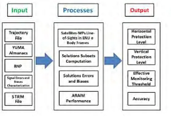
o Input and Output The tool takes as input:
The aircraft trajectory file
YUMA almanacs for the GNSS constellations
The high-resolution topographic data generated from National Aeronautics and Space Administration’s (NASA) Space Shuttle Radar Topography Mission (SRTM) ((NASA), 2000).
The tool provides as output for each trajectory waypoint:
Predicted ARAIM Performance with respect to the East North Up (ENU) reference frame (no shadow effect included, full view of the sky)
Predicted ARAIM Performance with respect to the aircraft body reference frame (both attitude and environment shadowing effect included)
Number of satellites in view in the two reference systems
[image:4.595.158.437.273.463.2] Number of satellites lost due to the shadowing effects
Figure 1summarises the flow chart and functions of the APPATT algorithm.
Figure 1. APPATT Scheme
2.2 FLIGHT PATH GENERATOR (FPG)
In ((ICAO), 2009), the International Civil Aviation Organization (ICAO) described design criteria to aid agencies in the implementation of RNP operational procedures. Moreover, the manual provides a basic model for the determination of manoeuvers based on two parameters: speed and bank angle.
The Flight Path Generator function takes as input a text file containing the list of waypoints for the selected procedure. The following are specified for each point:
- Name
- Latitude, Longitude and Altitude
- Type of WP (check WP, initial turn WP, turn WP, final turn WP, end of procedure WP)
- Turn type, if applicable (clockwise or counterclockwise)
- Preferred heading to next point
We assumed that the aircraft only performs a specific type of manoeuvre to change direction: fly-by turns.
TAS = IAS*171233*[(288+VAR) – 0.00198*H]0.5/ (288-0.006496*H)2.628 (1)
Where:
- VAR = variation from international standard atmosphere (ISA) (standard value +15) or local data for 95% high temperature, if available
- H = altitude (m)
However, the turn radius is calculated using the following equation for the speed:
V = TAS + assumed tailwind (TWD) (2)
Then, the rate of turn (R) in degrees/second can be computed as:
R = (6355*tan(α))/ (π*V) (3)
Where α is the bank angle.
And lastly, the turn radius is given by:
r = V/ (20* π*R) (4)
Knowing the radius of turn it is possible to compute the minimum distance from the turn WP at which the aircraft needs to start the turn manoeuvre, known as the Distance of Turn Anticipation (DTA), given by:
DTA = r*tan(A/2) (5)
Where A is the turn angle, the change of angle between the initial and final heading.
At this stage, the algorithm approximates the flight path to a series of connected lines and arcs in the 3D space using basic geometrical and kinematic equations. The generated path describes the aircraft trajectory in terms of position (latitude, longitude and altitude) and attitude (roll, pitch and yaw angles) in time within a user defined time step (e.g. 1s). In particular, the function monitors that the roll angle is always within the aircraft standard limits (the standard value for commercial flights is between 25-33°, but it can increase to a maximum of 60-70° in case of emergency).
The trajectory is then analysed by APPATT with the objective of evaluating the integrity performance of the trajectory considering the attitude. If it doesn’t satisfy the Required Navigation Performance and it presents one or more integrity outages, the Flight Path Modifier function is activated.
2.3 FLIGHT PATH MODIFIER (FPM)
In case of activation of the FPM function, the tool tries to modify the trajectory in order to remove the integrity outages and satisfy the Required Navigation Performance. The function analyses the trajectory section by section, examining which one needs to be modified.
Firstly, the function searches and memorises all of the turn points in the full list that it then analyses one by one, performing the following steps:
ending heading angles and turning points, given by the DTA (Figure 2 shows the initial waypoints, in red and green, and the initial and starting turn points, in blue).
- Checks the compatibility of the starting and ending turn points with the initial points, measuring their distance from the turn point. If one of the turning point distances is higher than the initial points, the tool checks their type in order to avoid conflicts between manoeuvres (e.g. if the following waypoint is a turn point too, the ending turn point of the previous manoeuvre can’t lay too close to the next one, otherwise the aircraft won’t have the time to end a manoeuvre before it will need to start a new one).
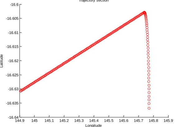
- If no incompatibilities are detected, the tool computes the trajectory of the current section, as shown in Figure 3.
144.9 145 145.1 145.2 145.3 145.4 145.5 145.6 145.7 145.8
-16.78 -16.76 -16.74 -16.72 -16.7 -16.68 -16.66 -16.64 -16.62 -16.6 -16.58
Trajectory waypoint
Longitude
L
a
ti
tu
d
[image:6.595.144.430.259.470.2]e
Figure 2. Initial waypoints, in red and green, and the initial and starting turn points, in blue
144.9 145 145.1 145.2 145.3 145.4 145.5 145.6 145.7 145.8 145.9
-16.64 -16.635 -16.63 -16.625 -16.62 -16.615 -16.61 -16.605 -16.6
Trajectory section
Longitude
L
a
ti
tu
d
e
[image:6.595.159.444.526.731.2]- Finally, the tool calls the APPATT function to compute the ARAIM performance parameters for the current trajectory section.
If the section presents an outage, the FPM performs the following steps:
- The function analyses the satellite which was lost due the attitude shadowing effect; if more than one satellite is not in view, it selects the satellite with the highest elevation angle and forces the aircraft to perform the manoeuvre with a bank angle smaller than the elevation angle. In this way, the satellite is again in the GNSS receiver’s field of view.
- If the new bank angle does not remove the outage, the tool selects as a new one the elevation of the next satellite lost in the list, and repeats this process until the outage is removed.
- Forcing the bank angle to a defined value modifies the values of the turn radius (r), the rate of turn (R) and the distance of turn anticipation (DTA). The function checks that the rate of turn stays within the standard values (for commercial flights R ≈ 3 deg/sec) and generates the new trajectory arc using the new DTA value.
- It then checks that the new arc segment is compatible with the provided waypoints.
- If an incompatibility occurs, the tool warns the user that with the current configuration the trajectory can’t be modified in order to meet the Required Navigation Performance
- The tool will then continue to analyse the following sections using the same procedure explained above.
3. SCENARIOS AND RESULTS
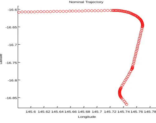
[image:7.595.172.425.521.722.2]The following results have been obtained from analysing the RNAV Standard Arrival Route (STAR) procedure Sunny Three Papa Arrival of the International Airport of Cairns (Figure 4), Australia, from the waypoint Konda, in a single constellation configuration (GPS).
Figure 5 shows the nominal trajectory with a banking angle of 25° for each turn manoeuvre while Figure 6 shows the aircraft attitude and Figure 7 to Figure 10 the ARAIM performance parameters.
145.6 145.62 145.64 145.66 145.68 145.7 145.72 145.74 145.76 145.78 -16.85
-16.8 -16.75 -16.7 -16.65 -16.6
Nominal Trajectory
Longitude
La
tit
ud
e
Figure 5. Nominal trajectory
0 50 100 150 200 250 300
-50 0 50 100 150 200
Aircraft Attitude
Waypoint
An
gle
s
(d
eg
)
[image:8.595.160.441.401.578.2]Roll Pitch Yaw
0 50 100 150 200 250 300 10
15 20 25 30 35 40
Horizontal Protection Level
Waypoint
HP
L
(m
)
[image:9.595.155.457.79.265.2]ref-ENU ref-Body Alert-Level
Figure 7. Horizontal Protection Level in the nominal trajectory
0 50 100 150 200 250 300
10 15 20 25 30 35
Vertical Protection Level
Waypoint
VP
L
(m
)
[image:9.595.166.446.306.489.2]ref-ENU ref-Body Alert-Level
Figure 8. Vertical Protection Level in the nominal trajectory
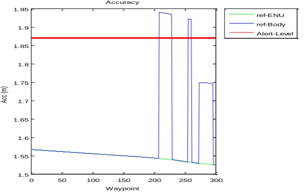
0 50 100 150 200 250 300
1.5 1.55 1.6 1.65 1.7 1.75 1.8 1.85 1.9 1.95
Accuracy
Waypoint
Ac
c
(m
)
ref-ENU ref-Body Alert-Level
[image:9.595.154.461.527.719.2]0 50 100 150 200 250 300 6
7 8 9 10 11 12 13 14 15
Effective Monitoring Threshold
Waypoint
EM
T
(m
)
ref-ENU ref-Body Alert-Level
Figure 10. Effective Monitoring Threshold in the nominal trajectory
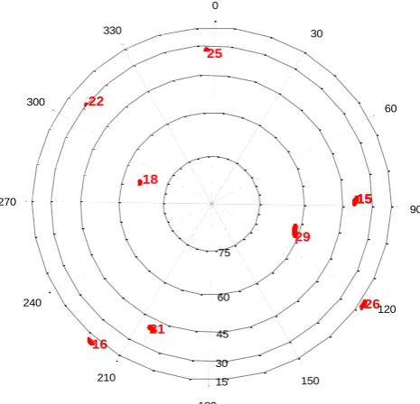
It is clear that each turn generates a peak, due to the loss of one satellite, GPS Pseudorandom noise (PRN) 25 for the first turn, PRN 26 for the second and PRN 16 for the last turn. In this configuration, the accuracy is only severely affected in the first and second turn. Figure 11 and Figure 12 show the difference in satellite in view between the ENU and body reference frames.
90 60
120 26 15 15 30
150 29 0
75
60
45
30
15
180 25
21 18 330
210 16 22 300
240 270
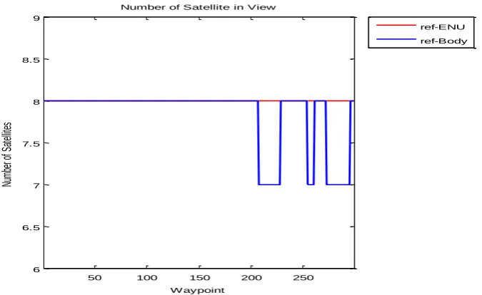
[image:10.595.192.425.385.609.2]50 100 150 200 250 6
6.5 7 7.5 8 8.5 9
Number of Satellite in View
Waypoint
Nu
m
be
r o
f S
at
ell
ite
s
[image:11.595.141.479.76.283.2]ref-ENU ref-Body
Figure12. Satellite in view in the ENU (red) and body (blue) reference frames in the nominal trajectory
50 100 150 200 250
-1 -0.5 0 0.5 1 1.5 2
Difference of Satellite ENU and Body and Terrain Shadowed satellites
W aypoint
Nu
mb
er
of
Sa
tel
lite
s
[image:11.595.117.506.355.575.2]diff-ENU/Body
Figure13. Difference of satellite in view between the ENU and body reference frames in the nominal trajectory
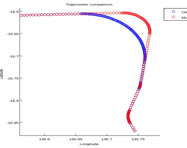
145.6 145.65 145.7 145.75 -16.85
-16.8 -16.75 -16.7 -16.65 -16.6
Trajectories comparison
Longitude
La
tit
ud
e
[image:12.595.103.414.77.322.2]Original Modified
Figure14. Standard trajectory (red line) and modified trajectory (blue line)
0 50 100 150 200 250 300 350
-50 0 50 100 150 200
Aircraft Attitude
Waypoint
An
gle
s
(d
eg
)
Roll
Pitch
Yaw
[image:12.595.138.496.385.611.2]200 250 300 350 -25
-20 -15 -10 -5 0 5 10 15
Aircraft Attitude
Waypoint
An
gle
s
(d
eg
)
[image:13.595.140.472.79.296.2]Roll Pitch Yaw
[image:13.595.154.454.419.634.2]Figure16. Focus on the modified roll angles
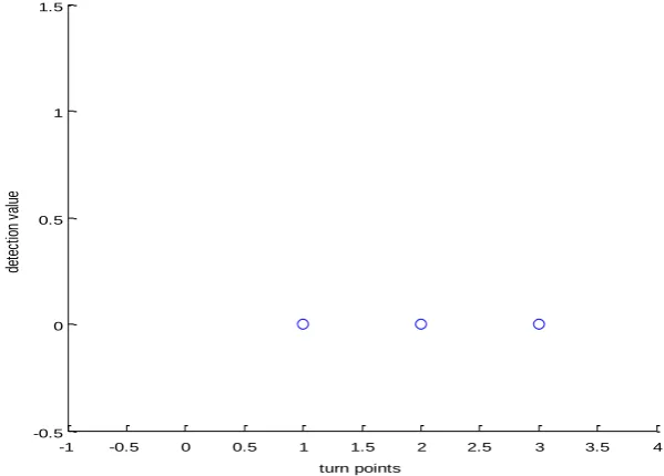
Figure 16 shows that the tool successfully modified the first two turns and the new trajectory does not present any incompatibility, Figure 17, while the third one is unchanged since the integrity parameters stay within the alert levels.
-1 -0.5 0 0.5 1 1.5 2 2.5 3 3.5 4
-0.5 0 0.5 1 1.5
Detection of trajectory incompatibilities (1 = detected, 0 = not detected)
turn points
de
te
ct
io
n
va
lu
e
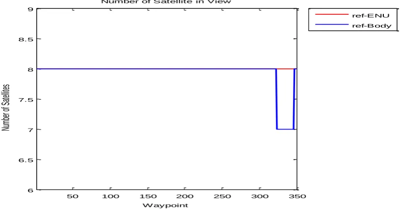
Figure 18 to Figure 23 show the number of satellites in view and the integrity parameters for the new trajectory.
50 100 150 200 250 300 350
6 6.5 7 7.5 8 8.5 9
Number of Satellite in View
W aypoint
Nu
mb
er
of
Sa
tel
lite
s
ref-ENU ref-Body
Figure 18. Satellite in view in the ENU (red) and body (blue) reference frames in the modified trajectory
50 100 150 200 250 300 350
-1 -0.5 0 0.5 1 1.5 2
Difference of Satellite ENU and Body and Terrain Shadowed satellites
W aypoint
Nu
mb
er
of
Sa
tel
lite
s
[image:14.595.100.503.400.615.2]diff-ENU/Body
0 50 100 150 200 250 300 350 10
15 20 25 30 35 40
Horizontal Protection Level
W aypoint
HP
L (
m)
[image:15.595.137.461.75.249.2]ref-ENU ref-Body Alert-Level
Figure 20. Horizontal Protection Level in the modified trajectory
0 50 100 150 200 250 300 350
10 15 20 25 30 35
Vertical Protection Level
Waypoint
VP
L
(m
)
[image:15.595.142.446.306.507.2]ref-ENU ref-Body Alert-Level
Figure 21. Vertical Protection Level in the modified trajectory
0 50 100 150 200 250 300 350
1.5 1.55 1.6 1.65 1.7 1.75 1.8 1.85 1.9
Accuracy
W aypoint
Ac
c (
m)
ref-ENU ref-Body Alert-Level
[image:15.595.121.459.545.725.2]0 50 100 150 200 250 300 350 6
7 8 9 10 11 12 13 14 15
Effective Monitoring Threshold
W aypoint
EM
T
(m
)
[image:16.595.124.461.77.269.2]ref-ENU ref-Body Alert-Level
Figure 23. Effective Monitoring Threshold in the modified trajectory
The previous graphs show that the modified trajectory does not present integrity outages, making the expected flight path safe in GPS nominal conditions.
4. CONCLUSIONS
The new algorithm allows the user to assess the benefits and limits of a selected procedure whether they are a procedure designer and tester or a pilot. Furthermore, Fig.(24) shows two possible applications of the algorithm, once enhanced with further functions such as no-fly zones and obstacle clearance controls, with the objective of providing a solution that oversees several problematic issues of an aircraft trajectory.
Moreover, the proposed tool could be used as an additional tool during the transition phase between the current procedures and navigation technologies and the introduction of GNSS as primary navigation system.
Increased awareness and better pre-flight planning could ultimately improve the safety of flights and contribute to the safe introduction of GNSS as a viable positioning method for instrument approach.
[image:16.595.188.407.522.689.2]REFERENCES
FEDERAL AVIATION ADMINISTRATION (FAA) 2007. AFS-400. Advisory Circular 90-100A - U.S Terminal and En Route Area Navigation (RNAV) Operations. In: FAA (ed.).
INTERNATIONAL CIVIL AVIATION ORGANIZATION (ICAO) 2009. DOC 9905 AN/471 – Required Navigation Performance Authorization Required (RNP AR) Procedure Design Manual.
NATIONAL AERONAUTICS and SPACE ADMINISTRATION (NASA) 2000. Shuttle Radar Topography Mission (SRTM) [Online]. Available: http://www2.jpl.nasa.gov/srtm/.
BLANCH, J., WALTER, T., ENGE, P., LEE, Y., PERVAN, B. & SPLETTER, A. Advanced RAIM User Algorithm Description: Integrity Support Message Processing, Fault Detection, Exclusion, and Protection Level Calculation. Proceedings of ION GNSS 2012, September 17-21 2012 Nashville, TN. pp. 2828-2849.
PATERNOSTRO, S., MOORE, T., HILL, C., ATKIN, J. & MORVAN, H. Evaluation of ARAIM Performance on Predicted Aircraft Trajectories. In: ION/IEEE, ed. PLANS 2016, 2016 Savannah, GA, USA. STANDFORD, U. 2014. MAAST download website [Online]. Available: