<http://orcid.org/0000-0002-6049-508X> and ZHANG, Hongwei
<http://orcid.org/0000-0002-7718-021X>
Available from Sheffield Hallam University Research Archive (SHURA) at:
http://shura.shu.ac.uk/25169/
This document is the author deposited version. You are advised to consult the
publisher's version if you wish to cite from it.
Published version
HAIRE, Matthew, XU, Xu, ALBOUL, Lyuba, PENDERS, Jacques and ZHANG,
Hongwei (2019). Ship Hull Repair Using A Swarm Of Autonomous Underwater
Robots: A Self-Assembly Algorithm. In: 2019 European Conference on Mobile
Robots (ECMR). IEEE.
Copyright and re-use policy
See
http://shura.shu.ac.uk/information.html
Sheffield Hallam University Research Archive
Abstract – When ships suffer hull damage at sea, quick and effective repairs are vital. In these scenarios where even minutes make a substantial difference, repair crews need effective solutions suited to modern challenges. In this paper, we propose a self-assembly algorithm to be used by a homogeneous swarm of autonomous underwater robots to aggregate at the hull breach and use their bodies to form a patch of appropriate size to cover the hole. Our approach is inspired by existing modular robot technologies and techniques, which are used to justify the feasibility of the proposed system in this paper. We test the ability of the agents to form a patch for various breach sizes and locations and investigate the effect of varying population density. The system is verified within the two-dimensional Netlogo simulation environment and shows how the system performance can be quantified in relation to the sizes of the breach and the swarm. The methodology and simulation results illustrate that the swarm robot approach presented in this paper forms an important contribution to the emergency ship hull repair scenario and compares advantageously against the traditional shoring methods. We conclude by suggesting how the approach may be extended to a three-dimensional domain to aid real-time implementation in the future.
I. INTRODUCTION
Innovations in materials, mechanical engineering, and naval architecture have ensured that the strength and resilience of ship hulls has remained steadfast this past century, but no sea-faring vessel is immune to accidental or deliberate damage. When a ship suffers a fracture or hull breach, the race to prevent the loss of the ship begins. Once a breach is detected, damage control crews are tasked with sealing off relevant compartments, plugging and patching holes from within the ship (shoring), and deploying pumps to remove sea water [1]. These repairs are essential to prevent excess listing of the vessel and restore stability, but shoring is a dangerous, time-constrained procedure that risks the lives of ship’s crew, and with modern naval services moving towards more intelligent autonomous sea faring vessels [2], relying on crew members to carry out these repairs seems less sustainable. To address this important issue, an approach to emergency ship hull repair using a swarm of autonomous underwater repair robots is proposed.
Using a swarm of robots to carry out the repair has many advantages over a single robot system [3]. Swarm-robot systems are typically more robust to unit failure, more scalable to different search spaces, and have the flexibility to adapt to different tasks.
¹
Corresponding Authors: [email protected]; [email protected] Matthew Haire, Dr Xu Xu, Dr Lyuba Alboul, Prof Jacques Penders and Dr Hongwei Zhang are part of the Centre for Automation and Robotics Research (CARR) and the Materials and Engineering Research Institute (MERI) at Sheffield Hallam University, England, United Kingdom.978-1-7281-3605-9/19/$31.00 ©2019 IEEE
In this approach, a decentralised group of homogeneous repair robots are used to inspect a ship hull, locate the damage, aggregate at the desired location and self-assemble to form a repair sheet of appropriate size using their own bodies. Once assembled, the newly formed robot patch is used to cover the breach and seal it, halting the ingress of water and allowing for safe deployment of pumps to drain the relevant compartments. Once realised, this solution could remove the requirement for ship’s crew to deal with most of the repairs, promoting greater autonomy of large sea-faring vessels and safeguarding the lives of crew. There are many aspects to this approach that require study such as optimal search patterns, navigation aspects, resilience to sensor noise, and adaptation to partial population failure, which will be addressed in a separate paper. This paper focuses on the self-assembly protocol to be used by the swarm once a breach has been located.
This paper will proceed as follows: Section II introduces key background literature used to formulate the approach and justify feasibility. Section III details the methodology, including the algorithm used by the swarm to perform self-assembly. Section IV outlines the experimental setup, presents results and identifies trends. Section V discusses the implications of our findings. Section VI concludes the paper with what has been achieved so far and describes future work, such as 3D implementation.
II. BACKGROUND
Self-assembly and modular robotics are two closely related fields of research which have seen significantly increased interest in the past 16 years [4-5]. Indeed, the existing literature is expansive covering many topics from morphology and re-configurability to behaviour and task allocation, but also highlights areas that require further development. Reviews of the current technology identify a need for systems that are truly scalable in terms of swarm size, robot module size, and practicality [5]. The approach proposed in this paper seeks to provide a practical application for a swarm of reconfigurable modular robots. The self-assembly protocol used by the swarm of repair robots is pivotal to the success of the emergency ship hull repair solution and is the focus of this paper. However, the robot modules used in simulation to demonstrate the self-assembly algorithm do not yet have a physical counterpart. As such, the robot module specifications are reduced to simple geometric shapes and a description of their abilities. The capabilities of the simulated robot modules are based on existing technologies found within the literature.
There are many existing mobile modular systems capable of self-reconfiguration [6-12]. These are systems that can navigate freely in a search space, capable of forming a
Ship Hull Repair Using a Swarm of Autonomous Underwater
Robots: A Self-Assembly Algorithm
required shape from scattered modules, and do not require human interaction to achieve required assembly. Such systems may assemble to create various formations, but a more notable example is that of the M-block robot [11] that can assume lattice structures, which are typically more resilient to shear forces than chain or truss shaped structures. Another aspect that affects resistance to external forces and the ability to hold a given shape is the type of connection used to join modules together. The two most common types of links used in existing systems are either magnetic or mechanical. Magnetic links allow for simpler attaching and releasing of modules and compare favourably to mechanical links. The Smart Blocks robot [13] is a prime example of a modular robot system capable of reconfiguration while maintaining bonds between units using magnetic links. In this paper, the simulated modules are assumed to form magnetic links between each other when attaching to form the repair patch.
The modules described thus far can be considered relatively self-sufficient since they are designed to operate using their own power supplies and can carry out actions independent of direct control. This seems to be a necessity to increase the ease of mobility and simplify the algorithms used to govern motion and guide re-configuration. Designing the system to be composed of homogeneous modules further helps simplify the control algorithm since any unit can theoretically occupy any position in the desired goal configuration [4]. Most aspects of modular robotics have been investigated on solid ground in both physical systems and simulations, but the domain we are interested in (underwater) is more dynamic in nature. Using a swarm of robots that can self-assemble to overcome difficult terrain has been explored in rough terrain environments [14-15]. However, modular robot systems that can be deployed in underwater environments are fewer in number. There are some modular underwater robots that have been developed through research [16-18], but none yet matches the morphology desired for the system proposed in this paper. The closest existing robots which could be used as a basis for the simulated robots in the experiments presented in this paper are the modular hydraulic propulsion robots developed by Doyle et al [19].
To achieve the desired self-assembly behaviour, the robot modules require sensors that allow them to gather adequate information about their environment, so they may orientate themselves and navigate effectively. The robots are intended to achieve localization by using a combination of small-scale gyroscopes [20], distance sensors, and a forward-facing camera to inspect the ship hull and use it as a point of reference. The modules may freely move in the fluid environment, but they should stay within range of the ship hull and work to maintain a set distance. This allows the modules to treat the environment more like a two-dimensional (2D) search space rather than a three-dimensional (3D) space - adding this constraint allows for the implementation of simpler algorithms for navigation and co-ordination.
The robots would be able to differentiate between an intact ship hull and a breach by using a combination of cameras and an on-board image processing tool to investigate their surroundings [21]. The camera may also be used to further reduce the errors in position estimation from the gyroscope and distance sensor readings by employing complimentary
localisation techniques [22]. The robot modules are intended to operate as a decentralised system, independent of any input from a master controller, but they still require methods of communication with each other to carry out the self-assembly protocol. For communication that can reach any of the modules at a given time, an active omnidirectional low frequency sonar system [23] could be used by the robots to signal when they have located a hull breach or detect when another robot is emitting such a signal. For local module-to-module interactions, LEDs and corresponding RGB colour sensors on each robot could be used, allowing each robot to communicate its state to local neighbours using their LEDs and examine the state of their neighbour’s state using their sensors. The reduced size, and power consumption of these devices compared to alternative methods make them ideal for use in a multi-robot system since the cost of such devices, and their power requirements, are less than that of more complex devices. Such efficiency and economic considerations are necessary if the system is intended for real-world implementation.
Communications between the robot modules, and their coupling/decoupling procedure, are assumed to be instantaneous. Some delay between module communication and linking is inevitable, but this issue falls outside of the scope of this paper and will be addressed in a future study. This study is concerned with the self-assembly protocol that will allow modules to form a repair patch of appropriate size, and how population density must be considered in order to achieve the fastest, most efficient response to a hull breach.
III. METHODOLOGY
The simulations for the self-assembly protocol are carried out in an open source simulation platform Netlogo - ideal for scenarios involving multiple agents with simple morphologies, operating in 2D environments. The simulated modules used in our experiments measure 5cm×5cm and can move one body length per simulation step, roughly equating to a top speed of 0.05 ms−1. The modules can freely move in the simulation
space but are unable to move through other robots and instead must give way to the units ahead of them, or to the right of them. They are always assumed to be able to maintain a set distance from the ship hull using their distance sensors, making the robots operate as though they are on the same plane. Modules can connect to each other using strong magnetic links and can also detach from each other easily. The robots use a small forward-facing camera to inspect the ship hull and choose an appropriate assembly point once the breach is located. Each robot is capable of two forms of communication: the first method (Fig. 1) uses sonar transmitters and receivers to send and receive the signal that indicates the location of the agent and the hull breach. The second method (Fig. 2) uses the LEDs and corresponding RGB sensors on each module that allows them to transmit their state in the form of a colour, and inspect the colour emitted from its neighbours, indicating their state.
deployed over the side of the ship and approach the reference point from above. Once robot modules have successfully navigated to the location of the first robot module, they may begin the assembly protocol. The protocol instructs agents to begin attaching to each other to form a block of connected robots that spans the diameter of the breach. The length of this block is determined by the cameras which can recognise when the modules have formed a line of adequate length. Once the first block has fully formed, the block advances by one module body-length (5cm) and the unattached modules begin forming a second block above the first, increasing the area of the patch. This process then repeats until every module on the perimeter of the breach can confirm they are not directly above the breach but are still connected to a module that is. In this case the robots enter their final state, and change their LED colour to purple, indicating the patch is ready. The result is a square sheet formed of robot modules which is large enough to cover the hole. The Pseudocode in Fig. 3 represents our algorithm, showing the protocol for navigation and the state transitions each robot module undergoes to form the resultant patch.
Fig.1. Robot module communication using omnidirectional low frequency sonar. The Robot that has located the breach transmits (Tx) the signal and robots that have not located the breach receive (Rx) and follow the signal.
Fig.2. Robot modules communicate their state with neighbours using LEDs (red, green, and orange circles) and RGB sensors (white triangles).
Algorithm 1 Self-Assembly Algorithm
1:begin program
2:
3: while unattached to block do
4: if agent ahead = false then
5: face reference point module.
6: move forward by 5cm.
7: else
8: if agent ahead = red then
9: move backwards by 5cm.
10: else if agent ahead = green then
11: attach to top of agent.
12: else if left neighbour of agent ahead = green then
13: attach to right side of block.
14: else
15: attach to left side of block.
16: end if
17: end if
18: end while
19:
20: while own state ≠ green do
21: if hull breach in line of sight = false then
22: own state = green.
23: else
24: if left neighbour state ≠ greenthen
25: own state = orange.
26: else
27: if right neighbour state ≠ green then
28: own state = orange.
29: else
30: own state = green.
31: end if
32: end if
33: end if
34: end while
35:
36: while own state ≠ purple do
37: if all neighbour states = green then
38: advance 5cm to cover hull breach.
39: if hull breach in line of sight = false then
40: own state = purple.
41: end if
42: else
43: if all neighbour states = purple then
44: own state = purple.
45: end if
46: end if
47: end while
48:
49: while breach ≠ sealed do
50: approach andseal hull breach.
51: end while
52:
53: end program
Fig.4. Netlogo simulated environment, showing robot modules carrying out the self-assembly protocol. The colours represent the LEDs on each face of the robot, indicating their state; Red for in transit, Orange for attached to an incomplete block, and Green for attached to a completed block.
The simulated environment (Fig.4.) consists of a rectangular arena, which represents a section of a damaged ship hull. The coloured cubes represent the robot modules that are either forming part of the patch (green and orange) or still in transit (red). The light grey area represents the section of ship hull above the waterline, the blue area is the section of ship hull beneath the waterline, and the black area represents the hull breach.
IV. EXPERIMENTS AND RESULTS
In all the experiments, robot modules are deployed at a steady rate ranging from 4 to 48 robots per minute. This is how we implement increases and decreases in population density and study the effect this has on the self-assembly process. Each set of variables tested represents the median value obtained from 50 consecutive experiments.
The first set of experiments address hull breaches ≤ 60 cm in diameter, since this represents the upper bound of common torpedo diameters [24]. In these scenarios, a single compartment is fully flooded but sealed off from other sections of the ship. The constants of this experiment are the shape of the breach, which was circular, the movement speed of the repair robots (0.05 ms−1), the speed of coupling and
decoupling of modules, and the speed of information exchange between the robots – both of which are assumed to be instantaneous. The variables of this experiment include the location of the hull breach, which ranges from 0.6m to 4.2m in depth, and the size of the breach which is between 10cm and 60cm in diameter. We use this information to determine the optimal amount of repair robots that should be deployed per minute to address these types of hull breach. The most notable sample of our graphs (Fig. 5) is provided to help identify trends.
The results from Fig. 5 show the number of robots in the swarm that remain unattached once the breach is sealed, and the time each simulation takes to complete against the number of robots deployed per minute. This information was used to determine the optimal amount of repair robots that should be present at once for breaches of difference sizes. Deploying fewer robots per minute yields the least number of robots that
remain unattached. However, the time taken to seal the breach is much greater when fewer robots are deployed each minute. A breached compartment needs to be sealed before pumps can be deployed to drain the compartment and help the ship regain stability. Therefore, in scenarios where the compartment is already fully flooded, time is a more heavily weighted constraint and repairing the breach quickly is the highest priority. The time taken to repair the breach increases minimally after a deployment rate of 36, but the number of robots that remain unattached increases significantly. Hence, it could be argued that the most optimal deployment rate is 36 robot modules per minute since this yields a sufficiently fast repair and minimises the number of unattached robots at the end of the simulation.
Fig.5. Results of first set of experiments using a breach diameter of 30cm. The top plot shows the time taken to form a patch of appropriate size at three different depths of breach. The bottom plot shows the number of robots that remain unattached at the end of each of the simulations.
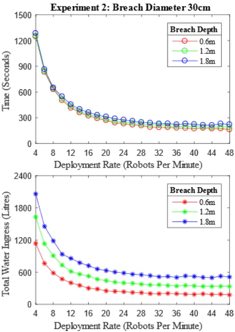
The second set of experiments also address hull breaches less than or equal to 60cm in diameter but attempt to seal the breach while an ingress of water is in progress – the goal being to minimise the ingress of water. The constants and variables of this experiment are the same as those of the first set of experiments, but now the flow rate of the water entering the compartment is also considered, which varies according to the size and depth of the breach. Equation (1) is used to determine the total volume of water that enters the container.
∆𝑉
where∆𝑉 is the volume difference of fluid flow in cubic metres (𝑚3), ∆𝑡 is the time interval in seconds (s), 𝐴 is the area of the
hull breach given in square metres (𝑚2), g is acceleration due
to gravity in metres per second squared (9.8 𝑚𝑠−2), and ℎ 1− ℎ2 is the difference in height of the water level inside the
[image:6.595.60.293.220.549.2]compartment and outside the compartment given in metres (m). We use this information to determine the optimal number of robots capable of sealing the breach with the least amount of water ingress, and again make use of the graph sample (Fig.6) to identify trends.
Fig. 6. Results from second set of experiments using a breach diameter of 30cm when water ingress is in progress. The top plot shows the time taken to form a patch of appropriate size at three different depths of breach. The bottom plot shows the total volume of water ingress that occurs for three different depths of breach.
Instead of measuring the number of robots that remain unattached, Fig. 6 shows the total volume of water ingress that occurred, and the time each simulation took to complete against the number of robots deployed per minute. This information is used to determine the optimal amount of repair robots that should be present at once for breaches of difference sizes. The method used by the robots to approach the breach means the robots are less effected by the ingress of water that would be expected if they were to hover directly above the breach. Hence the time taken to carry out the repair is largely unaffected, resulting in a similar length of time to repair the hull as those in the fully flooded compartment scenario. The results show that deploying a greater number of robots per minute yields the least volume of total water ingress, however the gains in time taken to repair the breach decay after a rate of 36 per minute is achieved. This decrease in time taken to repair
seems to be the result of overcrowding that occurs when too many robots are present within the same space at once, slowing the progress of their neighbours. Therefore, the most optimal deployment rate is 36 robots per minute since this results in fast repair, without suffering hinderances to swarm performance due to overcrowding.
The experiment codes we use can be accessed via our GitHub repository in [26], along with full videos of the simulation showing the self-assembly protocol.
V. DISCUSSION
The results indicate that a swarm of robot modules could use the self-assembly algorithm presented in this paper to repair a hull breach by forming a patch of appropriate size using their bodies. The experiments identified trends that hold across breach sizes and depths, namely that increasing the number of robots deployed each minute logarithmically decreases the time taken to repair the breach and the total volume of water that enters the hull. The diminished returns of time taken to repair are due to the overcrowding of robots near the top of the repair sheet. This effect could be mitigated by modifying the algorithm to allow agents to approach the repair sheet from all sides, and not just the top section closest to the waterline.
Increasing the robots deployed per minute also increases the number of robots that remain unattached at the end of the process, since the system is unaware of how many robots are required to repair the breach until the patch is formed. Deploying more robots than necessary to repair a breach is less economical than an adequate number being selected and by extension is less desirable. To realise a more optimal system, the next solution should include how to retrieve unattached robots at the end of the hull repair in order to reduce the cost of losing unattached robots. If the robot behaviour were to be expanded so that unattached modules could navigate to a point where they can be retrieved, this would further reduce issues regarding population density to a matter of deploying as many robots per minute as possible to seal the breach.
The results also identified a limitation of the current approach: when the breach is close to the waterline or if the repair robots approach the reference point at the wrong angle, the robots cannot connect to the robots already in place and the swarm fails to form an adequately sized repair sheet. This could be addressed by modifying the current procedure so that when the breach is located close to the waterline, the robot modules approach from beneath instead of above. The algorithms presented in this paper are conducted in 2D environments and serve as an important initial step towards realising the swarm approach for ship hull repair in emergencies. The next step would be to extend and test the current simulation algorithms in 3D environments.
In realistic scenarios, the repair robots will not be aware of the exact location of the hull breach and will have to undertake a search protocol before assembly can take place. Haire et al in [25] explore how this could be achieved in a 3D simulated environment. In their approach, they deploy robots along the side of the ship and have each member carry out an inspection of the ship hull using their cameras to determine the location of the breach. The repair robots that successfully locate a hull breach transmit their position to surrounding agents by emitting a sonar signal – indicating that there is a hull breach at their location.
If a similar inspection method was used in combination with the self-assembly approach in this paper, the repair robots could locate a breach, navigate towards the location, and begin their assembly protocol. However, to confirm the effectiveness of the algorithms presented in this paper, the experiments will need to be implemented in a 3D simulator. To further reduce the reality gap, the simulator should be capable of accurately modelling the physics of a fluid environment also.
VI. CONCLUSION
In this paper we have presented a new method of emergency ship hull repair using a decentralised swarm of autonomous underwater repair robots. We have identified a clear correlation between the number of robots deployed per minute to repair a breach, the speed of completion and the number of robots that will remain unattached given the population size. These results indicate that the new swarm robot approach could serve as a significant improvement over the traditional shoring methods provided the system can be implemented on a physical robot swarm. Future work will concern implementing these algorithms and modified variants in Webots, a simulator capable of modelling robots in 3D fluid environments, to see how they perform and bring these approaches closer towards implemented solutions. A real-world system may be achieved once simulations have been carried out and the swarm behaviours have been validated.
ACKNOWLEDGMENT
This work is supported and funded by Sheffield Hallam University through the Faculty of STA GTA scholarship program. We would also like to thank Dr Andreagiovanni Reina from the University of Sheffield for his valuable advice concerning decentralised systems and swarm robotics.
REFERENCES
[1] Center, N. (2013). Navy Damage Controlman - NAVEDTRA 14057 (Nonresident Training Course). [S.l.]: LULU COM.
[2] Ghaderi, H. (2019). Autonomous technologies in short sea shipping: trends, feasibility and implications. Transport Reviews, 39(1), 152–173. https://doi.org/10.1080/01441647.2018.1502834
[3] Brambilla, M., Ferrante, E., Birattari, M., & Dorigo, M. (2013). Swarm robotics: a review from the swarm engineering perspective. Swarm Intelligence, 7(1), 1–41. https://doi.org/10.1007/s11721-012-0075- [4] Ahmadzadeh, H., Masehian, E., & Asadpour, M. (2016). Modular
Robotic Systems: Characteristics and Applications. Journal of Intelligent & Robotic Systems, 81(3), 317–357.
https://doi.org/10.1007/s10846-015-0237-8
[5] Seo, J., Paik, J., & Yim, M. (2019). Modular Reconfigurable Robotics. Annual Review of Control, Robotics, and Autonomous Systems, 2(1). https://doi.org/10.1146/annurev-control-053018-023834
[6] Mondada, F., Guignard, A., Bonani, M., Bar, D., Lauria, M., & Floreano, D. (2003). SWARM-BOT: from concept to implementation.
In Proceedings 2003 IEEE/RSJ International Conference on Intelligent Robots and Systems (IROS 2003) (Cat. No.03CH37453) (Vol. 2, pp. 1626–1631 vol.2). IEEE. https://doi.org/10.1109/IROS.2003.1248877 [7] Rubenstein, M., Cornejo, A., & Nagpal, R. (2014). Robotics.
Programmable self-assembly in a thousand-robot swarm. Science (New York, N.Y.), 345(6198), 795–799.
https://doi.org/10.1126/science.1254295
[8] Sadjadi, H., Mohareri, O., Al-Jarrah, M., & Assaleh, K. (2012). Design and implementation of HexBot: A modular self-reconfigurable robotic system. Journal of the Franklin Institute, 349(7), 2281–2293.
https://doi.org/10.1016/j.jfranklin.2011.05.022
[9] Hong, W., Wang, S., & Shui, D. (2011). Reconfigurable robot system based on electromagnetic design (pp. 570–575).
https://doi.org/10.1109/FPM.2011.6045828
[10] Wolfe, K., Moses, M., Kutzer, M., & Chirikjian, G. (2012). M3Express: A low-cost independently-mobile reconfigurable modular robot. In 2012 IEEE International Conference on Robotics and Automation (pp. 2704–2710). IEEE. https://doi.org/10.1109/ICRA.2012.6224971 [11] Romanishin, J., Gilpin, K., & Rus, D. (2013). M-blocks:
Momentum-driven, magnetic modular robots (pp. 4288–4295). https://doi.org/10.1109/IROS.2013.6696971
[12] Gramescu, B., & Nitu, C. (2014). Modular Robot with Self-Reconfigurable Capabilities. Applied Mechanics and Materials, 555(Modeling and Optimization of the Aerospace, Robotics, Mechatronics, Machines-Tools, Mechanical Engineering and Human Motricity Fields), 352–357.
https://doi.org/10.4028/www.scientific.net/AMM.555.352
[13] Mobes, S., Laurent, G., Clevy, C., Le Fort-Piat, N., Piranda, B., & Bourgeois, J. (2012). Toward a 2D Modular and Self-Reconfigurable Robot for Conveying Microparts. In 2012 Second Workshop on Design, Control and Software Implementation for Distributed MEMS (pp. 7–
13). IEEE. https://doi.org/10.1109/dMEMS.2012.20
[14] Hongxing Wei, Youdong Chen, Jindong Tan, & Tianmiao Wang. (2011). Sambot: A Self-Assembly Modular Robot System. Mechatronics, IEEE/ASME Transactions on, 16(4), 745-757. [15] Kernbach, S., Meister, E., Schlachter, F., Jebens, K., Szymanski, M.,
Liedke, J., Ricotti, L. (2008). Symbiotic robot organisms: REPLICATOR and SYMBRION projects. Proceedings of the 8th Workshop on Performance Metrics for Intelligent Systems, 62-69. [16] Vasilescu, I., Varshavskaya, P., Kotay, K., & Rus, D. (2005).
Autonomous Modular Optical Underwater Robot (AMOUR) Design, Prototype and Feasibility Study. Robotics and Automation, 2005. ICRA 2005. Proceedings of the 2005 IEEE International Conference on, 1603-1609.
[17] Li, G., Gao, T., Dong, L., Liu, S., Xu, H., Lin, Y., & Jia, Q. (2016). A modular miniature underwater robot design scheme for swarm operations. OCEANS 2016 - Shanghai, 1-5.
[18] Moreno, & Shu-Yun Chung. (2014). SeaDrone: A modular and reconfigurable underwater robot for task optimization. OCEANS 2014 - TAIPEI, 1-7.
[19] Doyle, Xinyu Xu, Yue Gu, Perez-Diaz, Parrott, & Grob. (2016). Modular Hydraulic Propulsion: A robot that moves by routing fluid through itself. Robotics and Automation (ICRA), 2016 IEEE International Conference on, 5189-5196.
[20] Photonics; Researchers from California Institute of Technology Report Details of New Studies and Findings in the Area of Photonics (Nanophotonic optical gyroscope with reciprocal sensitivity enhancement). (2018, November 25). Journal of Technology & Science. [21] Wang, & Xie. (2014). An Adaptive and Online Underwater Image Processing Algorithm Implemented on Miniature Biomimetic Robotic Fish. IFAC Proceedings Volumes, 47(3), 7598-7603.
[22] Boudhane, & Nsiri. (2016). Underwater image processing method for fish localization and detection in submarine environment. Journal of Visual Communication and Image Representation, 39, 226-238. [23] Yusof, M., & Kabir, S. (2012). An Overview of Sonar and
Electromagnetic Waves for Underwater Communication. IETE Technical Review, 29(4), 307-317.
[24] Friedman, N. (2006). The Naval Institute guide to world naval weapon systems. Annapolis, Md.: Naval Institute Press.