Faculty of Electrical Engineering,
Mathematics & Computer Science
Analysis and Design of a
Dependability Manager
for Self-Aware System-on-Chips
Stephen A. Geerlings M.Sc. Thesis
August 2018
Supervisors:
This thesis describes the analysis, design, implementation and validation of a De-pendability Manager Core for Self-Aware System-on-Chips. This hardware is sup-ported by a redesigned software toolchain to allow reuse of IEEE 1687 (IJTAG) net-works. The Dependability Manager’s purpose is to be integrated into a large scale System-on-Chip. It will increase dependability of the system using software-based dependability applications. The application reuses IJTAG boundary scan test net-works during lifetime to increase dependability of system.
Many hardware and software solutions have been developed to improve depend-ability of System-on-Chips. The implementation of these solutions ranges from high to low level and design reuse is constrained in general. As complexity rises and manufacturing processes decrease over years, the industry must keep pace to guar-antee correct functionality of their computer products. Hardware design is a long process where reliability is a trade-off between risk and cost. Long lead times and high prices of wafer manufacturing threatens the design cycle, where multiple iter-ations improve the final product. A time-proven and universal platform for system reliability will help future hardware designers to minimize design cost and time while providing the same amount of reliability. This is the motivation behind the work in this research; creating a standardized programmable core that has can manage re-liability of a large scale system on chip.
This masters thesis constitutes the work for final graduation of the programme Embedded Systems at University of Twente, the Netherlands. This research follows a methodology for the design of an application specific instruction set processor. It has been adapted to suit the purpose of this research. It consists of analysing the application, creating a high level design and implementing and validating the hard-ware and softhard-ware separately. After which the two parts are combined and tested. Previous research along with the IJTAG standard provide a background of the appli-cation of a Dependability Manager. After the background information is presented, this thesis moves to create a high level design for the hardware and software. These sections are developed; the first as an RISC-V processor with memory mapped
vices for retargeting and interrupt management, the latter as a custom toolchain and system drivers. The toolchain features a redesigned PDL compiler, similar to previ-ous work, that creates an IJTAG framework to access the instruments in the network. Reuse of available tools such as the C compiler, Antlr, and VHDL memory IP speeds up the work. A Retargeting Engine for access to test networks and IJTAG interrupt manager are implemented and incorporated into the processor. Drivers along with a memory mapped IO system bus create a hardware abstraction layer that supports portability. The software toolchain and hardware implementation are validated by testing and eventually combined for a full integration test and quantification.
Hardware is emulated on an FPGA to show operation of a compiled program while benchmark networks from the Bastion project are used to show the correct operation of the PDL compiler. The retargeting engine is shown to operate on all Bastion Basic benchmark networks. The interrupt manager is tested with a special implementation of interrupt enabled network structures in a simple tree-network.
Although not perfect, the design of the dependability manager yields new ideas and entices the urge to develop a usable and matured IP core for dependability. The reuse of PDL scripts to generate a high level software framework makes them portable between different architectures and devices. It is a huge step compared to previous research into executing PDL in an embedded context. Practical issues have been found with converting PDL to static C which can be overcome with fur-ther research. The retargeting engine and interrupt manager have been validated to operate within the context of this research. The implementation of both hardware devices are tested and have been proven successful. The performance of the retar-geting engine is adequate but can be improved with caching. The interrupt manager operates according to its design and decreases the time for interrupt localisation tremendously. The dependability manager processor is simplistic without pipelining or caching. The dependability applications interface well with the generated PDL software frameworks. The hardware abstraction layer makes the interrupt manager and retargeting engine easily usable.
Stephen Geerlings
Summary iii
Glossary vii
1 Introduction and Problem Statement 1
1.1 Contributions . . . 2
1.2 Methodology . . . 3
1.3 Outline . . . 6
2 Related Work 7 2.1 Dependability Applications . . . 7
2.2 Dependability Management . . . 8
2.3 The IJTAG Standard . . . 10
2.4 Discussion . . . 19
3 Early Hardware/Software Codesign 21 3.1 Function of the Dependability Manager . . . 21
3.2 Architectural Design Exploration . . . 26
3.3 Hardware design . . . 37
3.4 Software design . . . 44
3.5 Discussion . . . 45
4 Software: Building the Toolchain 47 4.1 PDL to C Framework Compiler . . . 48
4.2 Compiler Implementation . . . 60
4.3 Drivers . . . 63
4.4 Toolchain . . . 66
4.5 Discussion . . . 66
5 Hardware: Creating the Dependability Manager 71 5.1 Processor . . . 71
5.3 Interrupt Manager . . . 82
5.4 TAP Control . . . 85
5.5 Validation of the Dependability Manager . . . 87
5.6 Discussion . . . 92
6 Experimental Results 95 6.1 Performance of the Retargeting Engine . . . 96
6.2 Performance of the Interrupt Manager . . . 102
6.3 Performance of the Dependability Manager . . . 104
6.4 FPGA Resource Usage . . . 105
6.5 Conclusion . . . 108
7 Conclusions & Future Work 111 7.1 Future Work . . . 113
References 115 Appendices A CSU Timing Diagram 123 B Retargeting Engine Memory 125 C The Mingle Network 127 D Detailed Modelsim Testbenches 145 E How to 149 E.1 Access the IJTAG PDL Compiler Source? . . . 149
E.2 Use the PDL2C framework compiler? . . . 149
E.3 Access the Dependability Manager Source? . . . 150
E.4 Use the RISC-V Compiler? . . . 150
E.5 Simulate the DM in ModelSim? . . . 150
E.6 Compile your own Dependability Application? . . . 150
iApply Applies the group of write, read or scan operations that has accummulated since the lastiApplycommand.
iCall Calls a PDL procedure defined by iProc from another
procedure.
iProc Defines a procedure that can be called. A procedure is
a collection of commands.
iRead Read a value from a register in the test network
dur-ing the nextiApply command. The command also can compare the read value to an expected value.
iReset Enforces that the reset port becomes asserted and a
target is set to its ICL defined reset state.
iWrite Write a value to a register in the test network during the
next iApply command. Arguments are the register or
port as defined in the ICL specification and the value that should be written.
AR-Stack Access Request Stack, a data structure of the retarget-ing engine that tracks the access requests and adds a new request on the stack if it is necessary to access a register or SCB.
AV Access Vector, a bit string that is shifted into the IJTAG network.
C The C programming language.
CSU Capture-Shift-Update, a process that captures data into a TDR, shifts it out and updates the instruments with data shifted in through the TAP.
DM Dependability Manager.
ESIB Extension of the SIB to store extra information as bit flags, in this research an interrupt flag which signals that the interrupt originated in the underlying segment. ESIB L A leaf node in the ESIB tree, performs similarly but does
not open the segment below as those elements are not ’active’ due to the Select signal being low.
FPGA Field Programmable Gate Array, a reconfigurable hard-ware capable of emulating digital integrated circuits.
gcc GNU C Compiler, the open source compiler for C that is ported to an impressive range of targets.
H-Array Hierarchy Array, a data structure that shows the ICL de-pendencies. It was introduced along with the traverse and generate algorithm for creating access vectors for IJTAG test networks.
HAL Hardware Abstraction Layer.
ICL Instrument Connectivity Language.
IJTAG Internal Joint Test Action Group develops the IEEE 1687 standard which is the successor of the JTAG stan-dard.
IM H-Array Interrupt Management Hierarchy Array, a data struc-ture that shows the network strucstruc-ture to locate interrupt sources.
IMU Interrupt Management Unit, used for managing inter-rupts coming from the extended IJTAG network.
IP Intellectual Property, a design for a component which can be licensed and reused for implementation.
ISA Instruction Set Architecture, the collection of operations a processor can perform and how they should be en-coded.
ISR Interrupt Service Routine, a function or piece of soft-ware that is executed when an interrupt is triggered by an external event.
JTAG Joint Test Action Group, the group responsible for the IEEE 1149 JTAG standard that allows test access of chips via boundary scan.
LSU Load Store Unit, responsible for loading and storing data between registers and the memory.
MIPS32 Instruction set based on the MIPS I and MIPS II instruc-tion set and it also added some features of III, IV and V. It was released next to a 64 bit version in 1999. It was also used as a base in the previous research.
MMIO Memory Mapped Input/Output.
PDL Procedural Description Language, scripting language defined by the IJTAG standard.
RE Retargeting Engine, a hardware device used for ac-cessing the IJTAG network.
RISC Reduced Instruction Set Computer.
RISC-V RISC-V is an open instruction set architecture devel-oped in academia and research and aimed at general purpose computing.
RSN Reconfigurable Scan Network, e.g. a IJTAG test net-work.
RV32I Base subset of the RISC-V instruction set architecture that features 32-bit integer addition and logic, condi-tional branching and jumping. It can be extended with floating point operations, multiplication and subtraction and other extensions.
ScanMux This network component of IJTAG acts as a switch. It is controlled by a scanmux control bit (SCB) and has at least two serial inputs and one output. It is a multiplexer of the scan chain of the test network.
SIB The Segment Insertion Bit is a network component of IJTAG to insert or skip a segment into the network, as defined in standard IEEE-1687, it is also an entry type in the H-Array.
SoC System-on-Chip.
TAP Test Access Port, an interface between the JTAG/IJTAG connection and the network.
Tcl Tool Command Language.
TDR Test Data Register, a component of the test network that stores data.
Introduction and Problem Statement
Scientific development has pushed the boundaries of chip production technology up to its physical limits. The quest for higher clock speeds, lower power consumption, better production yield and increasingly complex designs created a danger zone where lifetime of chips is shortened and reliability is compromised. Dependability of hardware, especially chips, is continuously threatened during lifetime as component failures occur randomly. This thesis is a step towards new ideas for chip reliability by managing chips during lifetime with software. By employing state of the art de-pendability procedures running on an embedded processor and reusing novel IJTAG test networks the chip can be monitored and dependability improved. Such a De-pendability Manager (DM) combined with a PDL cross compiler has been created for PDL based dependability procedures [1]. This work will extend the design with a functional retargeting engine (RE) [2], support for interrupt servicing [3] and high level language based dependability procedures.
Dependability procedures aim to improve the dependability of a system during lifetime. This system can be anything from a multi-core server processor to a com-plex mobile System on Chip (SoC). Dependability procedures exist on many layers of a system from hardware to operating system. Their goal is making a system more dependable but the procedures differ greatly in their methodology. Obviously, dependability procedures need interaction with the system to operate. Data about the system comes from sensors and other on-chip instruments and the output of the procedure must be applied to the system. Dependability applications are currently designed in an ad-hoc manner, often for scientific research. Reuse of these applica-tions in consumer or industrial products is problematic. Reuse is a significant money saver for chip designers and is encouraged by industry. Furthermore, dependability procedures implemented in a high level language could be used among different processors.
A new standard for internal instrument access is available since 2014. It improves on the tried and tested JTAG standard which was first named ’Boundary Scan’ in the IEEE 1149.1-1990 standard [4]. This boundary scan architecture meant to test the interconnects of a chip but over time has grown to test access in general and it became synonymous with JTAG. The new standard called IJTAG [5] employs a re-configurable scan chain to access internal instruments via a test access port. Its design goals are reusability and scalability meaning that instruments can be easily added to the network during chip design. A test host can use the network to access registers and instruments on the chip. However, usage of IJTAG is not limited to test-ing, the network can be used during lifetime to access instruments and safeguard correct functioning. An embedded processor would run a dependability procedure and use a retargeting engine to access this special network.
Not all chips will benefit from a dependability manager as its addition, along with the IJTAG network, incurs an overhead. The aim of the dependability manager is to govern heterogeneous complex SoCs. Such a system would most likely be man-aged by an operating system. The paradigm of a dependability manager hinges on the division of tasks in layers; functionality and dependability. If the functional layer, along with its operating system, undergoes some kind of fault then the dependability layer will notice and mitigate the problem. This dependability layer may be certified for use in vehicles or aircraft. Meanwhile the functional layer could undergo multi-ple revisions and can still rely on the same level of dependability. Making the DM feasible for as many chips as possible is a matter of costs. The overhead of a DM must be small. On the other hand, the DM could become a separate packaged chip. The design of scan networks enables the user to chain IJTAG devices on a printed circuit board together and a single DM could manage them all. In theory, the DM can be adopted to act as a separate IJTAG-programmer, i.e. a host-interface, to access or program devices during development. However, this thesis focusses on the first example; the DM as part of a large and complex SoC as in Fig. 1.1.
1.1
Contributions
Figure 1.1: Example System on Chip incorporating a DM reusing the IJTAG scan network.
processors with small costs.
The product created in this research is the Dependability Manager IP along with supporting software and drivers. The contributions of this research can be divided into the following.
• Implementation of a RISC-V RV32I instruction set processor.
• Realisation of a PDL to C-framework compiler.
• Implementation of a reusable retargeting engine IP device for IJTAG networks.
• Implementation of an interrupt management unit for the RISC-V processor.
• Implementation of interrupt enabled IJTAG SIB and localisation algorithm in the interrupt management unit.
1.2
Methodology
Figure 1.2: Design methodology and the products it yields, adapted for this project [6].
framework is originally exemplified by developing an Digital Signal Processor (DSP). The methodology has also been used in the previous work toward the DM [1]. The intention of this research is to extend a general purpose microprocessor with the retargeting engine and IJTAG IMU. Instead of creating a new application specific instruction set, an RISC instruction set is carefully selected for the application, i.e. the DM. In general, some steps in the methodology are unnecessary and skipped while others are slightly modified for this project’s purposes.
its abilities should be. This is formulated as a list of requirements. Design Space Exploration (DSE) optimises the processor but takes time as developing and testing a new design is arduous. Maintaining a ’Harvard’ architecture for the processor and focussing on the retargeting engine should yield a better design in the time frame.
Selection of the instruction set is entangled with the processor architecture. Trade-offs between them will bring them together. Development of an assembly emulator is not a goal of this project and relates more to ASIP feature testing. If the instruction set provides an assembly emulator it may be used to check the final design or test programs beforehand. High Level Language Compiler generation/development is a feature for ASIP production. The chosen instruction set architecture should provide one for this project to keep everything in the time budget. PDL Compiler is required to generate code that operates the Retargeting Engine. The HLL compiler and PDL compiler need to be verified, this can for example be done with the aforementioned assembly emulator to test the output.
The hardware development starts with designing an architecture around the cho-sen instruction set. Incorporation of the other system components is also part of the architecture. According to the methodology, a functional implementation can be made in a high level language (HLL) before switching to a hardware description lan-guage. This is similar to development of an emulator and as mentioned before not a step toward the goal. It is beneficial for ASIPs to be emulated and checked before further development [6]. For our architecture, it suffices to say that the algorithms behind the Retargeting Engine (RE) and the Interupt Management Unit (IMU) are already verified [2], [3]. The architecture implementation will create a base which will be extended in the hardware acceleration development step. This will yield a RE and IMU for IJTAG. The compiled programs, the base architecture and the exten-sions will need to operate together; trade-offs will define their relationship.
1.3
Outline
Related Work
This chapter attempts to give an overview of the state of the art in dependability man-agement in embedded systems. The scope is limited regarding dependability as the subject is immense and generally found in many fields of engineering. This chap-ter handles software-based dependability applications and hardware architectures to support dependability applications. A background of boundary scan architecture and test networks is provided as a fall-back for readers unfamiliar to the subject.
2.1
Dependability Applications
Dependability of a system is defined by its measure of reliability, availability, safety, maintainability and integrity [7]. Dependability applications form a collection of soft-ware algorithms made to increase these facets. Dependability applications can be incorporated into operating systems or added to an embedded program. A crude example is the screen saver feature in many desktop operating systems. The mov-ing images presented by the screen saver avoided ’burn-in’ in old monitors. Current versions of operating systems feature methods to dim or deactivate screens to save energy and prolong battery life.
These small examples are easily understood but the field of increasing depend-ability is interesting to say the least. Boundaries in engineering are pushed to get the most out of hardware. This hardware is not always created equal since it is a physical process [8]. Currently, in a process called ’binning’ the different tiers of chips are separated and they are sold according to their quality. The way chips are made creates a variability between devices. This is the first example of a depend-ability application that will be presented in this work. The varidepend-ability of devices can be measured to adapt the operation of software on the device [9]. This increases the yield of a silicon wafer but also increases the confidence that software can run
on less-than-perfect devices.
The second example of dependability applications focusses on the reliability and availability of systems. Dynamic Reliability Management continuously estimates the future reliability of a chip based on its current state [10]. For example, a server is bought and desired to run for at least 10 years. The amount of system degradation can be calculated based on physical properties. Processors suffer under high tem-peratures, voltages and current and a mean time to failure can be calculated based on these numbers. If the probability that it will fail before 10 years has passed be-comes too high the system needs to adapt and decrease temperature for example. However, the system must take into account that it has a certain workload, and that it will need to maintain a certain frequency to perform its job. Dynamic Reliability Management in general steers the processor based on a model of confidence but also needs to keep its workload in mind [11], [12].
2.2
Dependability Management
Dependable systems are ubiquitous. Bridges are ’over-engineered’ to withstand the test of time and the design of the internet is primarily redundant to ensure its functionality. Some special electronic systems are also designed to be dependable. Examples of this are computer memory for servers with error correcting code. Other examples are the RAD6000 [13] and LEON [14] processor designs which feature ionizing radiation resistance for use in outer space. Rigorous testing under set cir-cumstances tries to measure dependability of a device and to further improve the design. When it has undergone all possible tests and gets certified it cannot be changed easily. A new hardware revision takes months to produce new chips which need to be recertified before it may be used in cars or planes. Avoiding the uncer-tainty of new hardware has been a strategy in the Space Shuttle program at NASA, who were still searching for 8086 chips in 2002, two decades after their first re-lease [15].
cer-tified to give certainty to the developers of an application. And applications can be tested to document their performance. A better design for an application could quickly be tested and improved, thus functional revisions to the dependability layer can be made more often.
A dependability manager for a Dependable Reconfigurable Many-Core Proces-sor uses the Network-on-Chip interface to access cores in the chip [17]. Test vectors are generated for the core under test and the response is evaluated. Both JTAG and IJTAG can be used for communication through the dependability layer as it provides a standardized access method for instruments. These test networks are also present on many devices to find interconnect faults or to program the device. Reusing them during lifetime is a cost-effective method to add a dependability layer to an existing device [18].
An automated test coprocessor for JTAG was created for a MicroBlaze 32-bit processor [19]. The coprocessor has a simple microprogrammed control path to execute tests on the larger system through the boundary scan interface. The JTAG operations on the network where analysed and a minimal command set was created to support the test. Accessing JTAG from an embedded context has been done to execute tests during lifetime. For this a JTAG controller has been built that executes based on a FIFO queue [20]. This device could be reused to connect a DM to a JTAG network.
The management of hardware within hardware has also taken a step with the introduction of Intel’s Active Management Technology (AMT) which allows users to manage systems remotely [21]. Computer systems can be activated or deactivated with this daemon process within the hardware. The degradation and performance of systems was also presented to the user to let him repair components where needed. Among Intel’s line of products, the Intel Management Engine became well known due to its far reaching access to the hardware of consumers [?]. The separate em-bedded processor featured in many chips would be active even when a computer was shut down [?]. Connecting to a central platform would be a great feature for any Dependability Manager. It would allow companies to gain insight into the degra-dation of devices, similarly to Intel AMT. Considering the rise of Internet-of-Things (IoT) devices, this could become a reality.
PDL in a format, i.e. a grammar specification, supported by the Antlr4 parser gen-erator. The compiler compiles a modified version of PDL along with Tcl to MIPS32 assembly. The DM featured an empty shell for the retargeting engine and did not support the full MIPS32 instruction set. The future work suggested by the work of Zakiy includes: ’test for different processor, adding remaining PDL commands, cross compilation to other machines, and use of C libraries’. This research will take advantage of the lessons learned.
2.3
The IJTAG Standard
IEEE 1687-2014 Standard for Access and Control of Instrumentation Embedded within a Semiconductor Device [5], colloquially referred to as IJTAG is a new stan-dard developed by the Internal Joint Test Action Group. It provides methodology to access instruments within devices by reusing the Test Access Port (TAP), TAP Con-troller and Boundary Scan Architecture defined in the earlier JTAG standard [4]. It introduces a new version of the Procedure Description Language (PDL) along with the Instrument Connectivity Language (ICL). These technologies will be explained in this section to provide a background for the reader. Originally, the application of boundary scan architecture was to detect errors during manufacturing. For example, the scan cells can be used to probe signals to detect stuck-at faults on a printed cir-cuit board. Since then, the use of JTAG has grown beyond testing. Among its uses are programming devices, accessing internal registers and controlling the chip dur-ing debuggdur-ing. The role of JTAG has also grown in software design tools which can automatically load and execute a program on a device via JTAG. The rise in func-tionality, along with the rising hardware complexity prompted the development of the new standard. Its goals were, amongst others, to tackle the size of test networks and to support instruments with more functionality. The first was accomplished by adding network structures that add hierarchy and compartmentalises the network along with a description language that advocates reuse of network modules. The second goal is handled with PDL, a programming language targeted at electronic design automation and testing via the test network.
Listing 2.1: SIB module defined in ICL [23].
M o d u l e S I B _ m u x _ p r e {
S c a n I n P o r t SI ;
C a p t u r e E n P o r t CE ;
5 S h i f t E n P o r t SE ;
U p d a t e E n P o r t UE ;
S e l e c t P o r t SEL ;
R e s e t P o r t RST ;
T C K P o r t TCK ;
10 S c a n O u t P o r t SO {
S o u r c e SR ; }
S c a n I n t e r f a c e c l i e n t {
P o r t SI ; P o r t CE ; P o r t SE ; P o r t UE ;
15 P o r t SEL ; P o r t RST ; P o r t TCK ; P o r t SO ; }
S c a n I n P o r t f r o m S O ;
T o C a p t u r e E n P o r t t o C E ;
20 T o S h i f t E n P o r t t o S E ;
T o U p d a t e E n P o r t t o U E ;
T o S e l e c t P o r t t o S E L ;
T o R e s e t P o r t t o R S T ;
T o T C K P o r t t o T C K ;
25 S c a n O u t P o r t t o S I {
S o u r c e SI ; }
S c a n I n t e r f a c e h o s t {
P o r t f r o m S O ; P o r t t o C E ; P o r t t o S E ; P o r t t o U E ;
30 P o r t t o S E L ; P o r t t o R S T ; P o r t t o T C K ; P o r t t o S I ; }
S c a n R e g i s t e r SR {
S c a n I n S o u r c e S I B m u x ; C a p t u r e S o u r c e SR ; R e s e t V a l u e 1 ’ b0 ;
35 }
S c a n M u x S I B m u x S e l e c t e d B y SR { 1 ’ b0 SI ;
1 ’ b1 f r o m S O ; }
SIB
toSI fromSO
SI
01
SR
SO
Figure 2.1: Abstract representation of a SIB, not all Scan Interface signals are shown.
Table 2.1: Signals of a Scan Interface according to the IJTAG standard [5].
Signal Name Functionality
TCK (Clk) Clock signal for the test network. Elements operaate on the rising edge, except for the update operation which is falling edge.
Reset Reset signal for the test network, active high.
CaptureEn Signals that data must be captured from an instrument into the TDR. ShiftEn Signals that data must be shifted through the network.
UpdateEn Signals that all active TDRs must write their value to the instrument. ScanIn (SI) Serial data into the test network.
ScanOut (SO) Serial data from the test network.
Select (Sel) Select signal that activates a Scan Interface and subsequent interfaces.
2.3.1
Reconfigurable Network Structures
There are different structures within the test network that are defined in the stan-dard [5]. In general a Reconfigurable Scan Network (RSN) starts at the ’client in-terface’ which connects to a ’host inin-terface’. This network interface, referred to as the Test Access Port (TAP) consists of signals which can be seen in Table 2.1. The Instrument Connectivity Language (ICL) specification of a network or an instrument contains modules and instances. A module can be seen as a box with signals going in and out. Behaviour of the box and predetermined signals are specified with ICL keywords. The module specification for the SIB in Fig. 2.1 is shown in Listing 2.1. A module can be instantiated within the network specification.
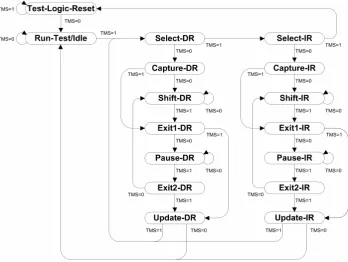
Figure 2.2: Test Access Port controller state machine, figure taken from the IJTAG standard [5].
Select’ signal. This state machine is shown in Fig 2.2. Its behaviour will be emulated by the DM’s hardware. The state machine executes cycles of Capture-Shift-Update (CSU-cycle) on the network to read and write data to the network. Most important to remember, is the sequence from theSelect-DR state. After parts of the network are activated by selecting them, the subsequent Capture-DR state will read data into the internal Test Data Register (TDR) of an instrument. The length and repre-sentation of this data is dependant on the instrument and must be managed by the retargeting tool. After capturing, the data will be shifted through the scan chain and new data will be shifted in to the network at the same time. Of course, this happens during theShift-DRstage. This new data is then written to an instrument during the Update cycle. There is always a Capture and Update stage, but the duration of the Shift cycle differs based on the length of active scan path. This length defines the size of the Access Vector (AV); the string of bits written to and read from the network.
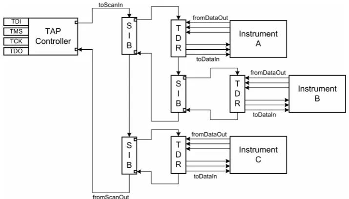
Figure 2.3: Hierarchical IJTAG Scan Network using SIBs, taken from the IJTAG standard [5].
to a SCB somewhere in the network. These structures offer the designer of a test network more versatility, optimise the design for fast access and provide hierarchy where needed. If no SIBs where placed in the hierarchical network of Fig 2.3 the shortest access vector would always be 3∗T DR.length. But with these structures the access vector size isT DR.length+ 2for the TDR connected to Instrument C.
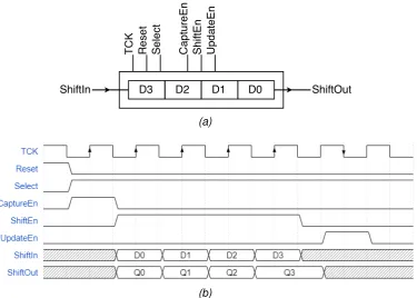
The data in access vector needs to have a certain order to wind up at the right place in the network. The data for the last element of the chain needs to be shifted in first. A nibble-sized example TDR is shown in Fig 2.4. The figure also contains a timing diagram of a CSU cycle along with the data in values (S0, S1..) and the data out values (D0, D1..).
ICL features more than is discussed here but this will suffice as a base for the remainder of this thesis. The design of ICL allows for many network configurations to be created. The remainder of this research will rely on the Hierarchy Array (H-Array) as a network specification. This data structure will be explained shortly.
2.3.2
Procedural Description Language
(a)
[image:25.595.128.504.84.352.2](b)
Figure 2.4: Timing diagram of a CSU cycle on a TDR Scan Interface.
be initialised to operate. It could also feature a self-test. Writing the code for those operations is error prone and tiring. An instrument designer can use PDL to write driver software to operate the device. The user of the device can then reuse the instrument and the code to quickly get up and running.
There are two levels of this language, namely PDL level-0 and PDL level-1. PDL level-0 is static in nature while PDL level-1 is dynamic. PDL level-1 incorporates Tcl which adds control flow to the language. Actually, when a file is deemed PDL level-1 the tool may expect Tcl statements along the code. This incorporates high level language components such as conditional branching in PDL. The base language is shown in Table 2.2 while the extra features are shown in Table 2.3. The operation of each command is discussed in Chapter 4.
PDL level-0 operates on the network with the ’scan commands’, the set of com-mands that issue reads and writes on the network. iWriteis responsible for writing to a register and iRead retrieves a value from a register. All scan commands are queued in an iApplygroup until they are applied to the network. The subset of the language is also responsible for procedures (iProc and iCall) which house these operations.
Listing 2.2: ICL along with PDL level-0 and PDL level-1 commands. Taken from the IJTAG standard [5].
ICL :
S c a n R e g i s t e r R e g A [ 5 : 0 ] { ... } ; S c a n R e g i s t e r R e g B [ 5 : 0 ] { ... } ;
5 A l i a s l b i t s = R e g A [1:0] , R e g B [ 1 : 0 ] ;
PDL :
i R e a d R e g A ;
i R e a d R e g B ( 3 : 0 ) 0 xf ;
10 i A p p l y ;
Tcl :
i G e t R e a d D a t a R e g A - hex ; # r e t u r n s a s t r i n g r e p r e s e n t i n g # a h e x a d e c i m a l n u m b e r
15
i G e t R e a d D a t a R e g B ( 3 : 1 ) ; # r e t u r n s a s t r i n g of 3 b i t s in b i n a r y
i G e t R e a d D a t a l b i t s - bin ; # r e t u r n s a s t r i n g of 4 b i t s in binary , # n o n e of w h i c h are ’x ’ , s i n c e all b i t s
20 # t h i s a l i a s r e f e r s to w e r e i R e a d
data from a device and to support a conditional flow through a test. An example of this can be found in Listing 2.2. The read data from a device can be used in Tcl after retrieving it. The test may go a different way based on the returned data from the network. Since this work will incorporate PDL in another high level programming language, the Tcl interface and support seems superfluous. More on this can be found in Chapters 3 and 4.
2.3.3
Structured Pattern Generation and Retargeting
The IJTAG networks are inherently master-slave and they need an entity to configure and control them. Specifically, IJTAG networks require a process called ’retargeting’ that reconfigures the active scan path to access an instrument [5]. This process can be compared with the operation of a railway-network; The railway’s switches need to be set appropriately to get a train from point a to point b. This sounds simple, but that is not all. In this case the order in which the switches are set matters; only the train driver can set the switches; and he can only do it when he passed the switch. At this point the analogy gets a bit vague. This subsection will try to explain the problems surrounding retargeting and discuss different approaches to solve them.
configu-Table 2.2: The set of PDL level-0 commands.
Command Example
iPDLLevel iPDLLevel 0 version STD 1687 2014;
iPrefix iPrefix core2.cpu;
iRead iRead temp register 0b1234;
iWrite iWrite temp register 0b1234;
iApply iApply;
iReset iReset;
iScan iScan foo 4 -si 0b0101 -so 0b1x0x;
iOverrideScanInterface iOverrideScanInterface core2.cpu -capture off; iOverrideScanInterface core2.cpu -update off;
iClock iClock foo;
iClockOverride iClockOverride foo -freqMultiplier 5;
iRunLoop iRunLoop 1000 sck foo;
iProcsForModule iProcsForModule foo namespace::core2 module; iProc iProc foo { arg1 {arg2 1234}} {
... ;
}
iUseProcNameSpace iUseProcNameSpace foo namespace;
iCall iCall foo 12 34;
iMerge iMerge -begin;
iCall proc1; iCall proc2; iMerge -end;
iNote iNote -status "Important Message"; iNote -comment "Hello World";
iTake iTake temp register;
iRelease iRelease temp register;
iState iState temp register 0b1101110011; iState SIB1 0b1;
Table 2.3: The set of PDL level-1 commands.
Command Examples
iGetReadData iGetReadData temp register hex ; iGetMiscompares iGetMiscompares temp register hex;
iGetStatus iGetStatus clear;
iCall myProc;
set num fails [iGetStatus]
ration, e.g. Fig. 2.3. For larger and more complex networks the problem forms a large Boolean equation. However, the order in which the SIBs and SCBs are set may matter in solving the equation. SAT solvers have been applied to perform re-targeting [24]. When it is clear which SCBs need to be set, the next step will be to determine how to get them in the active scan path. Solving this problem efficiently is crucial for automatic access in increasingly larger scan networks [2], [5], [16], [24], [25].
The approach using a SAT solver is applied in the research of Baranowski et al. [24]. The work focusses on reduction of test time and robustness of a tool to formally verify a network’s layout. The automatic pattern generation has been ap-plied to benchmark networks and different experiments were held, for example to reduce access time or to merge multiple concurrent access requests. The research suggests that optimal pattern generation also implies taking care of closing the seg-ments that are not needed any more.
The algorithm by Ibrahim for retargeting is based on an Access Request stack and a Hierarchy Array [2]. The H-Array shows the dependency relation between SIBs or ScanMuxes and their underlying instruments. This is done through the cre-ation of a Selection Dependency Graph based on the ICL specificcre-ation. The graph representation is then translated to the H-Array [2], [26]. To start retargeting the net-work, the access request stack is filled with one or multiple entries for instruments. Basically, an access request is created for every iWrite and iRead in the iApply
group. If an SCB needs to be changed for access to an instrument, it is pushed on the the stack of that instrument. If a SCB is on the active scan path, its new value will be put in the access vector. This opens the necessary segments of the IJTAG network and the instruments can be accessed. The work does not present a method to close a segment of the network. This project will focus on the work of Ibrahim as its ”execution model” is applicable in the embedded setting of the DM [2], [16], [25].
2.3.4
IJTAG Tools
tools and benchmark networks (in PDL, ICL and VHDL) made available by the Bas-tion project [23], [27]. These benchmarks contain ICL, VHDL, PDL and figures of different IJTAG networks. Some of the networks are based on the popular ITC’02 benchmark collection [28]. One of the networks, the Mingle network, is a versatile example that features all kinds of structures. This network has been used to test the automatic generation of the H-Array from the Selection Dependency Graph [26]. The benchmark networks can be used to test all the operation of the Retargeting Engine and PDL compiler.
Other tools that are available are aimed at the design of IJTAG compliant IP. Au-tomatic generation of ICL and PDL based on hardware and automated testing of developed IP are among the suites provided by different companies [29]–[31].
As mentioned, the previous work by Zakiy [1] offers a PDL compiler to MIPS32 assembly code. This compiler could be refurbished to fit the needs of this project. However, the supported syntax of the compiler is an adapted version of PDL and Tcl. Due to the nature of compiler generation with Antlr, it may be more feasible to start from scratch.
2.4
Discussion
Early Hardware/Software Codesign
This chapter will move through the first steps of the design methodology presented in the work of Jain et al. [32], see Fig 1.2. The methodology begins with a design phase analysing the problem, then combining hardware and software into a single solution. After that it moves to separate the tracks for implementation. This chapter explores the design space and creates a complete picture of the DM before moving further with implementation.
3.1
Function of the Dependability Manager
The adopted methodology starts with an application analysis to gather information about the domain of Dependability Management. This domain is characterized by the dependability applications and the operation environment. There are different dependability applications and some generalisations will be made to know what the DM shall execute. The operation environment provides a setting in which the DM will exist and hardware needs to be designed accordingly.
In Section 2.1 some examples of dependability applications are given. These algorithms to manage dependability all need a form of input from sensors. To ac-tively manage a system they also need an actuator. This is the definition of a control system as shown in Fig. 3.1. A control system consists of a controller, sensors, and actuators, see Fig 3.1. The system calculates the error between the setpoint and the measured value (PV). This error value is then used to steer the actuators. Many control algorithms exist for different purposes. Control systems are used in many fields of engineering; one of the first examples is the use of a so-called Governor
on steam engines. It maintains a steady speed by managing the amount of steam let into the engine [33], [34]. With the rise of digital systems came the control algo-rithms. These are used to measure and actuate within milliseconds and they are the
(a)Control System (b)Using IJTAG
Figure 3.1: Similarity of a Control System and Dependability Manager using IJTAG.
driving force behind drones, rockets and industrial plants.
The dependability manager will also operate as a control system using sensors and actuators in the IJTAG network. This is also shown in Fig 3.1. The setpoint is stored in the DM or calculated as part of the dependability application. The in-put and outin-put of sensor and steering values is done by shifting values through the IJTAG scan chain. The actuation rate of most dependability algorithms is low [10], as seconds pass between updates. This makes the use of IJTAG as a means of control system possible, at least for dependability applications. The clock speed for JTAG and IJTAG is affected by multiple factors. Normally, JTAG programmers are connected via a cable to the printed circuit board. The layout of the test access network may cause a clock speed limitation due to signal propagation delay. Typ-ical clock speeds for JTAG programmers is 1 to 50 MHz, the higher the speed the more expensive the unit. To guarantee operation of control algorithms on the IJTAG network, the following assumptions about it are made.
• Proper scan path optimisation to the required sensors and actuators.
• High throughput communication with the retargeting engine.
• A high availability of the IJTAG network.
• An average to high clock speed for the IJTAG network.
instruments to support the process of binning processors. The research into em-bedded instruments for IJTAG is ongoing and different instruments are adopted to be used within the network. Temperature, current and potential difference (voltage) sensors have been wrapped by an interface layer for IJTAG [1], [35]–[37]. The same approach for sensors can be taken for actuators. Thus the usage of dependability applications is limited by theneed of these actuators in the test network.
Dependability is a measure of a system’s availability, reliability, maintainability, integrity and security. A dependability application is defined as a software solution to improve dependability of a system. A dependable system implies maintainability of the system and by definition a dependability application needs to be maintainable to ensure its purpose. To create some scope of the domain in which the DM will operate different forms of dependability applications are discussed.
Variability Management Creating a processor in silicon is a physical process and not all chips are made the same. Multiple units are made on one wafer and sub-sequently cut into separate pieces, called a die. Each unit is then tested to finalize the manufacturing process. This test will check if all cores are functional or what the maximum sustained clock speed is. The chips are then sorted into separate bins [8], [38]. These bins give the practice its name;binningincreases the yield from a waver as partially working cores can still be used.
The variability in the produced chips is a key issue in modern many-core proces-sors. Binning is one of the options to mitigate the differences among processors and improve yield. The processors are tested after manufacturing and are clocked and configured accordingly. The variability among processors is not only noticeable after manufacturing but also during lifetime as the degradation of chips is also a physical process [9], [39]. The battery of a mobile phone or notebook computer will not keep the same capacity over time and the amount of power it can deliver at a given time will decrease. This has led to Apple under-clocking certain smart phones with a software update as the battery could not supply the phone with power [40].
be tested by executing benchmarks to check its operation [8]. The dependability application then proceeds to (de)activate components that have degraded or it de-creases clock speeds to allow correct operation of affected areas. This could hurt performance of the system in general and some form of communication with the functional layer could be beneficial [16].
Reliability & Availability Management Where the subject of the previous para-graph simply accepted the reality of failing components, the field of Dynamic Re-liability Management (DRM) tries to take it a step further. The physical process of degradation has been mapped and analysed to provide models of the environmental effects on degradation. These models are used to estimate the lifetime of a com-ponent, i.e. the mean time to failure. The goal of Dynamic Reliability Management is to give certainty that the component does not fail before reaching its lifetime goal while executing a certain workload.
The DRM algorithm proposes to manage a SoC’s different failure modes by em-ploying reliability models [10]. Temperature and voltage are the main causes of oxide breakdown, a reaction where the gate oxide of a MOSFET fails. This, among other failure modes of the semiconductors, are taken into consideration in the DRM algo-rithm. The algorithm calculates total reliability by analysing the different blocks on the chip. The workload of the device is also monitored and a gaussian distribution is fitted to it. A confidence function is used to create an estimator for the remainder of the work that needs to be executed in the chips lifetime. Knowing the proces-sor’s utilisation and its intended lifetime lets the algorithm calculate the likelihood of chip survival in those environmental conditions. The algorithm then steers the clock frequency and voltages applied to the device to lower temperature and voltage. Al-though this may reduce performance, the survival of the chip is guaranteed with a higher certainty.
The algorithm is optimised with the look-up-table approach but features extensive arithmetic to make proper decisions. The algorithm was validated with a simulated approach but also was implemented and tested for 24 hours. The update interval of the algorithm was 10 minutes as this should be enough on the long term. The calculations for expected workload etc. should easily be performed within that time.
Fault Management Faults can occur at any time in a device. They are technically defined as the cause of errors. If an error reaches the service interface and alters the service it will result in a failure. Managing faults will limit the potential ensuing damage of a failure. For example, a fault in the clock signal of a data bus may lead to erroneously read values. These values may change the system behaviour and this becomes a failure. An intermittent resistive fault instrument used to detect timing issues can notify the DM that a fault occurred [35]. This notification can also hap-pen with interrupt enabled IJTAG [3] which triggers a service routine to manage this occurrence. The interrupt enabled IJTAG architecture allows automatic scan path re-organisation to localize the interrupt. The test network configuration is not affected after the interrupt. There are multiple strategies in fault handling for dependability [7] based on the faults origin. Having a reactive system such as the interrupt manager will aid the end user to manage notifications of the instrument without continuous polling.
3.2
Architectural Design Exploration
The general concept of a dependability application is sketched in the previous sec-tion of this chapter. This secsec-tion will continue with this input to explore the architec-tural design space [32]. Questions about the high level language compiler, instruc-tion set, and other architectural features needs to be answered. At the end of the section, the interaction between software and hardware should be clear. This will allow for independent implementation of the two according to the methodology.
Figure 3.2: Design choices for the DM affect each other.
3.2.1
Instruction Set Architecture
A massive amount of Instruction Set Architectures (ISA) have been designed and implemented by processor manufacturers around the world. They are often reused or extended over the years, and some are backward-compatible. Instruction sets are classified, e.g. RISC, CISC, VLIW, based on features, size, functionality and purpose. A suitable instruction set is needed for the DM that fits its particular func-tionality, size and purpose. The instruction set is also required to feature an assem-bler and compiler for a high level language. The decisions for high level language and instruction set rely heavily on each other as can be seen in Fig. 3.2.
The work of Zakiy argues the use of MIPS (Microprocessor without Interlocked Pipeline Stages) as instruction set in its dependability manager [1]. The MIPS series architecture is chosen because the original MIPS I/R2000 ISA was published as an openly available architecture by its creator John L. Hennesy. MIPS I is a RISC ISA and the design features support for moving data to and from coprocessors. MIPS Technologies has made multiple iterations of the MIPS architecture. The MIPS I has been incorporated in the MIPS32 standard [41]. This ISA contains the full MIPS32 ISA which consists of multiple extensions, e.g. MIPS I, MIPS II, and this standard remains under intellectual property protection.
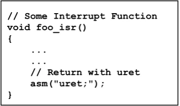
These custom instructions also raise the question on how these they can be ex-ecuted from the context of a high level language. The PDL-compiler automatically converted iRead, iWrite, and iApply to coprocessor instructions [1]. This is not an option as this new version will reuse an existing high level language compiler, such as gcc. The coprocessor-specific instructions should be usable from a high level language with inline assembly programming as shown in Fig. 3.3. This feature allows a programmer to incorporate assembly for increased performance and direct control of hardware. Some instruction sets like MIPS32 and RISC-V are extendible for application specific purposes, and a RISC computer can be extended to become an ASIP. This approach has the downside that the retargeting engine IP core will become less portable, and thus usable in other projects as the design is tied to the custom instruction set.
The approach of Zakiy’s design [1], i.e. the coprocessor-specific instructions for the retargeting engine, affects the use of high level language. Not all high level lan-guages allow for inline assembly programming or linking with custom machine code. A different approach than the ASIP solution is found in the Memory-Mapped I/O (MMIO) architecture and dedicated drivers for the retargeting engine and other DM subsystems. In general, drivers connect high level software with low level hardware. The MMIO architecture is further explained in subsection 3.3.
This leaves the choice for an ISA wide open. The results of the dependability application analysis in subsection 3.1 reveal that a RISC instruction set should suf-fice. High level language support is required for the ISA along with interrupt service routine features. Most dependability applications are some form of control algorithm so arithmetic must be supported. The high level language should also offer some mathematical libraries for computations. Relevant candidate ISAs are reviewed to find a suitable option. All discussed instruction sets are supported by gcc, so the project can fall back on C/C++ as a high level language. The requirements for the instruction set for the DM are drafted accordingly:
• The ISA must have high level language support, specifically a compiler for a preferred programming language.
• The ISA must have arithmetic and control logic that supports the execution of a compiled high level language program.
• The ISA must have interrupt support to enable the execution of interrupt ser-vice routines.
• The ISA should be considered RISC as this group features small and simple hardware designs.
• The ISA should be available for use in this academical project without license fees.
The amount of instructions in the ISA directly corresponds to the effort needed to implement the processor. More instructions mean more work as design, imple-mentation and validation of the processor is needed. However, if an architecture offers extendible implementations for this project it may be worthwhile to consider integrating it in this project.
The exploratory search into RISC architectures yielded the following candidates which are briefly discussed and compared in Table 3.1. All the ISAs in the table feature high level language support, arithmetic and control logic and memory oper-ations, so this is left out of the table. The table shows the word size in bits of the architectures, which typically corresponds to the register size for these ISAs. The third column contains the amount of instructions in the instruction set. This is an important factor for implementation and complexity of the hardware. Next to that are the amount of general purpose registers. Finally a classification is given for the sup-porting software. This column is denoted as ’Toolchain’ and more stars means the supporting resources are better. It is a classification based on amount of resources, software, emulators and other useful information surrounding the instruction set. The table shows whether interrupts are supported and if the ISA is ’Open’, i.e. not protected against use in this project.
Figure 3.3: Example of inline assembly programming in C.
Table 3.1: Comparison of instruction set architectures.
ISA Bits Instr. Regi. Toolchain Interrupts Open
RV32I 32 50 32 FFFF X X [42]–[44]
MIPS I 32 112 64 FFF X [46]–[48]
MIPS32 32 177 64 FFF X [41], [47], [48]
OpenRISC 32 48 32 FF X X [49], [50]
OpenSPARC 64 140 640 FFFF X X [51]–[53]
MICO32 32 61 32 FFF X X [54], [55]
MMIX 64 134 256 F X [56]–[58]
author is unfamiliar with Verilog and Scala.
The requirements for this project are covered by the ’RV32EN’ extension, where ’E’ stands for the ’embedded’ base instruction set. This reduces the number of gen-eral purpose registers from 32 to 16. It also drops the need for operations that access the control status registers of the core. The ’N’ extension covers the abil-ity to use user-level interrupts but both extensions are still in development. The workaround here is implementing all the general purpose registers and only use parts of the ’N’ extension. This means supporting the RV32I base instruction set. Surprisingly it is possible to employ ’N’-operations such asuretfrom C if we rely on inline assembly programming as can be seen in Fig 3.3.
MIPS I and MIPS32 are taken into consideration as it enables reusing previous work into the Dependability Manager [1]. Toolchain support is also extensive as MIPS is used in industry. However, implementing a MIPS32 compatible processor is an arduous task considering the amount of instructions. It is possible to eliminate part of that work by omitting the floating point coprocessor and using gcc with cor-responding flags. Still Table 3.1 shows the amount of instructions when hardware floating point operations are disabled. Adding that to the fact that MIPS is propri-etary technology makes it a bad choice.
accompanying simulator, hardware implementations and SoC design that feature the OpenRISC 1000 (or1k) processor [49]. They have ported Linux to their ISA and offer many tools to use the architecture [59]. Their ISA is also modular, the base instruction set is called ORBIS32 and features the same benefits as RISC-V.
The OpenSPARC architecture is available for use but it is not suitable for this project. It has a large amount of instructions and its 640 64-bit registers are certainly too much. There are more suitable ISAs. SPARC stands for Scalable Processor Ar-chitecture and is designed for data centers. OpenSPARC T1 was released as an open version of the UltraSPARC T1 for educational purpose [51]. This architecture complies with ARMv9 Level 1 and its features are described in Table 3.1. Presum-ably it features an extensive toolchain as the UltraSPARC is used in industry and is compatible with different operating systems. However, the amount of operations and the required general purpose registers makes it unsuitable for an small embedded environment.
The MICO32 RISC architecture has been made for use on Lattice Semiconduc-tor FPGAs. The architecture software and hardware is available as source code and features interrupts and external device support [54]. The available soft core is implemented in Verilog. The device is feature rich and is ready for incorporation into this project. However, unfamiliarity with Verilog is the main reason to avoid using this architecture implementation.
The MMIX architecture was developed by Donald Knuth for educational pur-poses. Support for the project by the community seems limited and only a hardware implementation in Verilog is available. However, the incredible amount of registers for an embedded system, lack of interrupt support and scarcity of tools and docu-mentation make this a poor choice for this project.
3.2.2
High Level Language
This research is a continuation of the work towards the dependability manager [1]. The previous project had no support for a high level language. Proper integration of a high level language compiler is an important feature in this work. The choice for a high level language support for an embedded system is dictated by the instruction set. Since this choice was already made we rely on the tools available. For the sake of completeness this subsection discusses high level languages that can be used to program dependability applications. Next to the compatibility of the programming language with the instruction set, the suitability and supporting libraries of the lan-guage are discussed. Rust, C/C++, Python and Java are evaluated as high level languages regarding their support and limitations for running on targets.
Rust is a new concept programming language where memory and thread safety is guaranteed [62]. It is syntactically similar to C++ but adds new mechanics to en-sure its intended goal. All values in the system have an implicit owner upon creation and are immutable unless otherwise specified. Current fully-supported targets for rust are the x86 and x64 architectures while other targets are supported with limita-tions [63]. There currently is no support for RISC-V, nonetheless, Rust would be a great language for dependability applications considering its safety features.
C and C++ are often named in the same breath and are considered the industry standard for programming embedded systems. C++’s object-oriented-programming characteristic is an added layer of higher level functionality to C. The language is considered mid-level as it lacks ease-of-use features present in modern high level languages such as garbage collection. C is compatible with many targets due to the design of its open source compiler that eases effort required for creating a cross compiler. The RISC-V architecture also features a cross compiler [60] to create bare metal code for the DM. Applications written in C are able to access memory locations directly which enables the MMIO operation of the DM’s system devices. In general, function attributes can be used to declare interrupt service routines although this is not yet supported for RISC-V. Maintainability and readability of C applications require an effort on the programmer’s part but adhering to code style conventions mitigates this problem [64], [65].
the chosen ISA. The Cython compiler translates Python to C code and then compiles to a Python module usable from the Python environment or from a C application. A dependability application can be made in Python and compiled to C and then com-piled with a target-gcc [69].
Java is a popular programming language and supports many devices [70]. Java is compiled to Java byte code and subsequently executed by the Java virtual ma-chine. Any target that features a virtual machine is able to execute Java programs. To support RISC-V an openly available virtual machine needs to be cross compiled, such as Avian [71]. Java was not designed to allow MMIO partly due to the virtual nature but some virtual machines feature direct access to memory nowadays [72].
The choice of ISA affect the high level language support tremendously. Python and Java feature the same method of operation, albeit a virtual machine or an in-terpreter, and both languages will require effort to run on the RISC-V ISA. Rust’s benefits are enabled for certain targets, e.g. x86 and x64, but not (yet) supported for the RISC-V architecture. This leaves the GNU gcc toolchain supplied by the RISC-V developers. Using C for this project is beneficial as it is an industry-proven language with a long successful history. It can run bare metal which reduces the code size and improves the processing speed.
3.2.3
PDL Incorporation
Now the discussion between ISA and high level language support is completed a design is needed to incorporate the PDL programs. First an introduction to and pre-vious work on the PDL compiler will be given as it is a starting point for how the programmer could use the DM. After a design is made to effectively use PDL speci-fications from a high level point of view.
(a) (b)
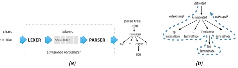
Figure 3.4: Language recognizer generated from a grammar changes input file to tree structure which is then walked. Custom code is called to perform the necessary actions at each node. Figures taken from the Antlr4 Definitive Reference [73].
The work of Zakiy introduced a PDL compiler from one complete PDL/Tcl script to an assembly program [1]. This compiler is based on the Antlr project which turns a BNF syntax grammar specification into a usable Lexer, Parser and Walker for an Abstract Syntax Tree (AST) [22], [73]. The Lexer will read a program and turn it into a stream of tokens. This tokenstream is parsed and stored as a tree data structure. This AST can then be walked by an observable TreeWalker object which calls func-tions in an observer class upon entering and exiting a tree node. The process is shown in Fig 3.4.
Zakiy’s syntax grammar specification incorporates Tcl next to the PDL syntax in align with the IJTAG standard that defines that PDL level-1 programs may fea-ture Tcl. However, Tcl is not a standardized language (reserved keywords may be redefined) which introduces the problem that no grammar was available and had to be reverse engineered. The IJTAG standard features an Antlr grammar for PDL (and also one for ICL) language and was modified to parse a subset of Tcl [1]. Un-fortunately during this process many concessions where made and the resulting grammar could only be used to compile custom PDL code,iProc andiCallwhere completely ignored. It was not able to compile BASTION benchmark files [27].
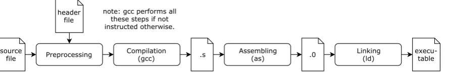
stan-Figure 3.5: Steps of the GNU C compiler.
dard. The second option is to compile a Tcl interpreter for the DM and let it run PDL files directly on the target. The normal Tcl interpreter (tclsh) program is too large to fit on most embedded systems. A minimalistic interpreter such as Partcl [74], [75] could be used, it is extendible with custom Tcl commands which would be the PDL definitions and has been tested on an embedded system. The custom commands would control the retargeting engine and the interpreter would be configured for PDL. However the project is considered a ’toy project’ by its creator, would require the whole dependability application to be written in Tcl and would be a far reach from the previous work. This leaves the PDL compiler as remaining option.
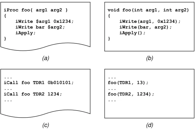
Among the choices for compiler output are high level language, assembly, and machine code. gcc uses these intermediate formats, see Fig. 3.5, and using these formats eases the integration of PDL and C. Some form of interfacing is required for using the PDL from the dependability application. So, basing the design on what tools are available is a reasonable choice. Assembly (.s) and machine code (.o) offer a complete control over the machine. However, compiling to assembly come with challenges. Storing and loading of variables needs to be managed, includ-ing the locations in memory. All administration of the machine needs to be done. The PDL compiler itself will also be responsible for managing the symbols (function and variable names) encountered in the PDL. Calling procedures in assembly must be correct. And the output of the compiler must adhere to the standard for linker files [76]. This is a tremendous amount of work compared to outputting high level language code. Fig. 3.6 shows the ease of converting the PDL syntax to C. Although this approach also has its challenges, the gcc compiler can manage the symbols, calling structures, and system management. This approach will only require correct parsing and symbol management of the PDL.
[image:45.595.96.542.87.164.2](a) (b)
[image:46.595.118.453.93.313.2](c) (d)
Figure 3.6:Two examples of how PDL can be converted to C.
by generating a new lexer and parser and filling the stubs, is necessary considering the grammar differences. The ISA used in the previous work is hard-coded into the compiler. The syntax specification is readily available from the IJTAG standard [5], so generating a new compiler with Antlr is trivial.
The previous work mentions portability as an option for future work [1]. In order to support any machine, and provide a hardware abstraction layer (HAL), a paradigm shift is needed for the compiler. This HAL consists of two parts: the instrument PDL library/framework and the retargeting engine drivers. To use the hardware effec-tively from software a layer of ’driver’ software is created. This can also be seen in Fig 3.6; iWrite and iRead are functions in the retargeting engine driver. If the hardware changes, only the drivers will need to be updated to ensure the software executes. The other part, the instrument PDL library, will be a translation of the PDL file accompanying a instrument. The code in such a file is always contained iniProc
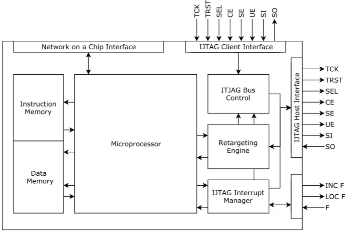
Figure 3.7: High level system block diagram.
3.3
Hardware design
A high level design for the dependability manager is discussed in this section. The application analysis showed no need for a specifically fast architecture. Recall that updates in the control algorithm happen with seconds in between. The calculations performed by the DM will be intermittent. Simplicity is at the core of the DM, to re-duce implementation time and increase maintainability. Construction of performance increasing technologies such as pipelining and branch prediction will remain out of the scope of this project. The microprocessor will need multiple clock cycles per instruction as it moves through its execution stages. The focus during implementa-tion will be on the retargeting engine and interrupt management unit. These will be necessary components to cope with the IJTAG networks.

![Figure 1.2: Design methodology and the products it yields, adapted for thisproject [6].](https://thumb-us.123doks.com/thumbv2/123dok_us/9677646.469513/14.595.58.506.83.511/figure-design-methodology-products-yields-adapted-thisproject.webp)