Language
.
Reference GUide
Ultimate
THE ULTIMATE CORP.
(
The Ultimate Corp.
East Hanover, NJ
© 1989,1990 The Ultimate Corp., East Hanover, NJ All Rights Reserved.
Printed in the United States of America.
How to order this guide:
The Ultimate Assembly Reference Guide is a restricted document. For information on ordering, call the Ultimate Administration Department.
Publication Information
This work is the property of and embodies trade secrets and confidential information proprietary to Ultimate, and may not be reproduced, copied, used, disclosed, transferred, adapted, or modified without the express written approval of Ultimate.
Operating System Release 10, Revision 210
© 1989, 1990 The Ultimate Corp., East Hanover, NJ
How to Use this Manual ... xvii How the Manual is Organized ... xviii Conventions ... xx
1 Overview of Assembly Language ... 1-1 The Ultimate Virtual System Architecture ... 1-3 User Processes in a Multi-User System ... 1-5 Process Workspaces ... 1 -6 The Kernel Software ... 1-8 Process Scheduling ... 1-1 0 Frame Faults ... 1-11 Automatic Disk Writes ... 1-13 Calls (MCALs) from Processes ... 1-13 Main Memory Management ... , ... 1-13
2 The Assembler ... 2-1 The Components of an Assembly Program ... 2-2
Displaying the Program ... 2-3 Creating an Assembly Language Program ... 2-4 Assembly Structures ... 2-5 Mode Structure ... 2-5 Mode-ids - External Program References ... 2-7 Program Line Structure ... 2-9 Displaying Assembly Programs in the Editor ... 2-12 The Assembler Program ... 2-1 5 Executing Assembled Programs ... 2-17 The AS Command - Firmware Assemblies ... 2-18 The OPT Command -S/370 Assemblies ... 2-21 The ASM Command - 1400 Assemblies ... 2-23
The Optimizer ... 2-26 Assembler Error Messages ... 2-27 OSYM Errors ... 2-28 Generating Object Code ... 2-29 Directives and Object Code ... 2-29 Instructions and Object Code ... 2-29 Generating Object Code ... 2-30 Symbol Files ... 2-31
The OSYM File Layout. ... 2-35 Symbols and Literals ... 2-44 Locally Defined Symbols ... 2-44 Literals ... 2-45 Shared Symbols (INCLUDE Directive) ... 2-48 Immediate Symbols ... 2-48 Assembler System Commands ... 2-50 CROSS-INDEX ... 2-51 MLIST ... 2-53 MLOAD ... 2-55 MVERIFY ... 2-56 X-REF ... 2-59 XREF ... 2-61
3 Addressing and Representing Data ... 3-1 Frame Formats ... 3-2
Frame Size ... 3-2 Link Fields ... 3-5 ASS Frames ... 3-7 Data Formats in a Frame ... 3-8 Virtual Addresses - Addressing Data in a Frame ... 3-1 0 Understanding Address Registers ... 3-13 Attaching an Address Register ... 3-15 Loading an Address Register ... 3-16 Conventional Usage of Address Registers ... 3-16 Understanding Storage Registers ... 3-19 Addressing Modes in an Instruction ... 3-21
Immediate Addressing ... 3-21 Relative Addressing ... 3-21 Indirect Addressing ... 3-22 Direct Register Addressing ... 3-23 Symbol Types ... 3-24 Computing Relative Addresses by Symbol Type ... 3-26 Limits in Offsets ... 3-27 Addressing the PCB Fields ... 3-29 The Accumulator ... 3-29 Scan Characters ... 3-33 File Control Block Pointers ... 3-35 Subroutine Return Stack Fields ... 3-36 XMODE Field ... 3-37 RMODE Field ... 3-37 WMODE Field ... 3-37
iv Assembly Manual 6973-1
Confidential and Proprietary to The Ultimate Corp.
( " \
(
... OVRFLCTR Field ... 3-37 INHIBIT and INHIBITH Fields ... 3-38 Addressing the SCB Fields ... 3-39 Addressing Conventional Buffer Workspaces ... 3-39 Programming Conventions ... 3-44 Global Symbolic Elements - PSYM File ... 3-45 Sharing Object Code Among Processes ... 3-46 Defining Additional Workspace ... 3-48 Ensuring Compatibility ... 3-484 Assembler Instruction Set and Dlrectives ... 4-1 Summary of the Instructions and Directives ... .4-2 Operand Types ... 4-5 Virtual Addresses ... 4-6 System Delimiters ... 4-6 ADD ... 4-7 ADDX ... 4-7 ADDR ... 4-9 ALIGN ... 4-11 AND ... 4-12
(
B ... 4-13 BBS ... 4-14 BBZ ... 4-14 BCA ... 4-15 BCNA ... 4-15 BCE ... 4-16 BCU ... 4-16 BCH ... 4-18 BCHE ... 4-18BCL ...
4-18 BCN ... 4-21 BCNN ... 4-21 BCNA ... 4-22 BCNN ... 4-22 BCNX ... 4-22 BCU ... 4-22 BCX ... 4-23 BCNX ... 4-23 BDHZ ... 4-24 BDHEZ ... 4-24BDZ ... 4-26 BDNZ ... 4-26 BE ... 4-28 BU ... 4-28 BH ... 4-31 BHE ... 4-31 BL ... 4-31 BLE ... 4-31 BHZ ... 4-34 BHEZ ... 4-34 BLl ... 4-34 BLEZ ... 4-34 BL ... 4-36 BLE ... 4-36 BLl ... 4-36 BLEZ ... 4-36 BNZ ... 4-36 BSL ... 4-37 BSL * ... 4-40 BSLI. ... 4-41 BSTE ... 4-42 BU ... 4-44 BZ ... 4-45 BNZ ... 4-45 CHR ... 4-46 CMNT ... 4-47 DEC (Data) ... 4-48 INC (Data) ... 4-48 DEC (Register) ... 4-50 INC (Register) ... 4-50 DEFx ... 4-52 DEFM ... 4-60 DEFN ... 4-61 DEFNEP ... 4-63 DEFNEPA ... 4-63 DIV ... 4-68 DIVX ... 4-68 DTLY ... 4-70 FTLY ... 4-70 HTLY ... 4-70 TLY ... 4-70 EJECT ... 4-72
MTL Y ... 4-1 34 ~,,,j;>J MTLYU ... 4-134
MUL ... 4-135 MULX ... 4-135 MXB ... 4-137 NEG ... 4-138 NEP ... 4-139 NOP ... 4-140 ONE ... 4-141 OR ... 4-142 ORG ... 4-143 OUT1 B ... 4-146 OUT1 BX ... 4-1 46 RQM ... 4-147 RTN ... 4-148 SB ... 4-149 SET.TIME ... 4-150 SETDSP ... ~ ... 4-151 SETR ... 4-153 SHIFT ... 4-155 SICD ... 4-156 SiD ... 4-161 SIDC ... 4-161 SIT ... 4-164 SITD ... 4-164 SLEEP ... 4-167 SR ... 4-168 SRA ... 4-170 STORE ... 4-172 SUB ... 4-173 SUBX ... 4-173 TEXT ... 4-174 TIME ... 4-175 TLY ... 4-176 XCC ... 4-177 XOR ... 4-178 XRR ... 4-179 ZB ... 4-180 ZERO ... 4-181
5 System Subroutines ... 5-1 Summary of the System Subroutines ... 5-2
Conventions Used to Describe System Subroutines ... 5-6 File Control Block Symbols ... 5-7 ACONV ... 5-9 AND IOFLGS ... 5-1 0 ATIOVF ... 5-11 CONV ... 5-12 CRLFPRINT ... 5-12 CVD ... 5-13 CVX ... 5-13 DATE ... 5-15 DECINHIB ... 5-16 ECONV ... 5-18 GETACBMS ... 5-19 GETSUF ... 5-20 GETFILE ... 5-21 GETIOFLGS ... 5-23 GETITM ... 5-24 GETOVF ... 5-27 GETBLK ... 5-27
PRINT ... 5-50 CRLFPRINT ... 5-50 PRNTHDR ... 5-52 RDLINK ... 5-54 WTLINK ... 5-54 RDREC ... 5-55 READ@IB ... 5-56 READX@IB ... 5-56 READLIN ... 5-57 READLINX ... 5-57 READIB ... 5-57 RELBLK ... 5-60 RELCHN ... 5-60 RELOVF ... 5-60 RESETTERM ... 5-61 RETIX ... 5-63 RETIXU ... 5-63 RTNMARK ... 5-65 SETLPTR ... 5-66 SETTERM ... 5-66 SLEEP ... 5-68 SLEEPSUB ... 5-68 SORT ... 5-69 SYSTEM-CU RSOR ... 5-72 TERM-INFO ... 5-85 TIME ... 5-87 DATE ... 5-87 TIMDATE ... 5-87 TPBCK ... 5-88 TPREAD ... 5-89 TPWRITE ... 5-89 TPRDBLK ... 5-89 TPREW ... 5-92 TPWEOF ... 5-93 UPDITM ... 5-94 WRITE@OB ... 5-96 WRITEX@OB ... 5-96 WRTLIN ... 5-97 WRITOB ... 5-97 WSINIT ... 5-1 00 WTLINK ... 5-102
x Assembly Manual 6973-1
(
6 System Software Interfaces ... 6-1 Interfaces Between TCl and User Programs ... 6-3
The Initial Conditions of a Process at TCL. ... 6-3 CONV Interface ... 6-5 Calling Conversion Program as a Subroutine ... 6-5 Calling a User-Written Subroutine ... 6-8 PROC Interface ... 6-10 RECAll Interface ... 6-13 Gaining Control After Selection ... 6-14 Gaining Control After Processing Codes ... 6-15 Element Usage ... 6-18 TCl-1 and TCl-1I Interfaces ... 6-24 TCl-1 Interface Requirements ... 6-27 TCl-1I Interface Requirements ... 6-30 WRAPUP Interface ... 6-33 WRAPUP Entry Points ... 6-34 XMODE Interface ... 6-36
7 Programmer's Reference ... 7-1 Hints ... 7-2
(
Guidelines for Data Moves and String Conversions ... 7-4 Guidelines for Defining Symbols ... 7-7 Two's Complement Arithmetic Concepts ... 7-8 Examples ... 7 -1 0TCl-1 Verb and BASIC Program ... 7-11 TCl-1I Verb and BASIC Program ... 7-13 Conversion Subroutine ... 7-15 Setting Up Heading and Footing Area ... 7-17 PROC User Exit ... 7-18 Cursor and Printer Control ... 7-19 Returning a Port's logon PCB Frame ... 7 -22 Returning Time in Milliseconds ... 7-23 Handling BREAK Key Activity ... 7-24 Changing Width on Wyse Terminals ... 7-25
8 The System (Assembly Language) Oebugger ... 8-1 Entering the Debugger ... 8-2
Displaying Data in the Debugger ... 8-11 Changing Data in the Debugger ... 8-14 A Command - Display Address ... 8-16 Arithmetic Commands ... 8-17 B Command - Breakpoint Specification ... 8-18 Bye Command - Exiting the Debugger ... 8-19 D Command - Display Tables ... 8-20 DI Command - Disabling the Debugger ... 8-21 E Command - Execution Step ... 8-22 END Command - Exiting the Debugger ... 8-23 F Command - Changing Frame Assignments ... 8-24 G Command - Resume Execution ... 8-25 K Command - Clear Breakpoints ... 8-26 l Command - Display Link Fields ... 8-27 M Command - Modal Execution Trace ... 8-28 N Command - Delay Entry to Debugger ... 8-29 P Command - Toggle Terminal Display ... 8-30 T Command - Trace Data ... 8-31 U Command - Delete Traces ... 8-32 Y Command - Data Breakpoint ... 8-33 », «, >, < Commands - Changing TCl levels ... 8-34 9 Monitor Calls (MCAls) ... 9-1
How to Use MCAl Information ... 9-4 ALARM.ClOCK - MCAl 1 C ... 9-6 ClEAR.INP _ MCAl 33 ... 9-7 ClOCK.CANCEl - MCAl 1 D ... 9-8 ClR.OUT - MCAl 36 ... 9-9 DB.ENT - MCAl 10 ... 9-10 DB.lV - MCAl 11 ... 9-11 DISK.ERR - MCAl 24 ... 9-12 DISK.STAT - MCAl 38 ... 9-13 DSABL.DSK - MCAl 2C ... 9-14 FAKE.RD - MCAl 14 ... 9-15 FAKE.READ - MCAl 49 ... 9-17 FAKE.WT - MCAl 15 ... 9-18 FORCE.WRITE - MCAl 25 ... 9-19 FRM.lOCK - MCAl 21 ... 9-20 FRM.UNlOCK - MCAl 20 ... 9-21 GET.ID - MCAl 9 ... 9-22 INT.CANCEl - MCAl 1 E ... 9-23 lINK.CNT - MCAl 3 ... 9-24
(
LOCK - MCAL 29 ... 9-25 LOCK - MCAL 2A ... 9-27 MTS - MCAL 4 ... 9-29 MTSF - MCAL 2 ... 9-30 N.GET.ID - MCAL 1 A ... 9-31 PANEL - MCAL 0 ... 9-32 PC.MSG - MCAL 48 ... 9-33 PERIPH.RD - MCAL 40 ... 9-34 PERIPH.RD.ONE - MCAL 35 ... 9-35 PERIPH.WRT - MCAL 41 ... 9-36 PERIPH.WRT.ONE - MCAL 34 ... 9-37 PIS.AND - MCAL 12 ... 9-38 PIS.ATL - MCAL 2S ... 9-39 PIB.OR - MCAL 13 ... 9-40 PIB.PEEK - MCAL 18 ... 9-41 PIB.POKE - MCAL 19 ... 9-42 PIB.XPCB _ MCAL 37 ... 9-43 QUERY - MCAL 17 ... 9-44 QUEUE.READ - MCAL 20 ... 9-46 RCV.LEN - MCAL 3A ... 9-47XFER.ClOCK - MCAl 3E ... 9-72
1 0 Instruction Set for Internal Use ...•... 1 0-1
Summary of the Instructions and Directives ... 10-2 :0 ... 1 0-4 :F ... 1 0-4 :Q ... 1 0-4
:T ... 1
0-4 :INIT ... 10-5 SISYNC.IO ... 1 0-6 Sequence for Data Transmission ... 1 0-9 Processing Interrupts ... 10-10 SNREAON ... 10-11 REAON ... 1 0-11 REAOT ... 10-11 CRC ... 10-14Mask Byte ... 10-15 OCD ... 10-17 FRM: ... 10-19 HlT ... 10-20 ISM.OS.TRAP ... 10-21 lOCK ... 10-22 MCAl ... 10-23 MCOOE ... ; ... 10-23 MODEM ... 10-24 MP ... 10-25 MSG ... 10-26 MTEXT ... 10-26 MV ... 10-32 MVER.OFF ... 1 0-33 MVER.ON ... 0 . . . 10-33
POPN ... 10-36 POPS ... 10-36 PUSH x ... 10-39 R1 EQU ... 10-42 REV ... 10-45 RPlOCO ... 10-46 RTNX ... 10-47 SCHR ... 10-48 SETAR ... 1 0-49 SETDO ... 10-50 SETDO ... 1 0-50
(
SHTl Y ... 10-52 SlEEPX ... 1 0-53 SMOD ... 10-54 TIIDC ... 10-55 Mask Byte ... 1 0-56 VIO ... 10-58 VIOlD ... 1 0-58 VM ... 10-61 XBCA ... 10-62 XBCNA ... 1 0-62
Figures
1-1. Virtual Memory System ... 1-4 1-2. Processes ... 1-5 1-3. Process Work Space ... 1-7 1-4. Main Memory layout ... 1-9 1-5. Frame Fault ... 1 -12 3-1. Frame Formats ... 3-4 3-2. Data Formats and Bit Numberings ... 3-9 3-3. Register Displacement Involving Linked Set of ... 3-13 3-4. Address Register Format. ... 3-14 3-5. Relative Addressing of Symbols ... 3-26 3-6 Primary Accumulator Area ... 3-30 3-7. Mask Byte Format.. ... 3-34 4-1. SICD Mask Byte Format.. ... 4-157 6-1. Processing Codes ... 6-7 6-2. TCl-1 Verb Definition Item Format ... 6-24 6-3. TCl-1I Verb Definition Item Format.. ... 6-25 Tables
2-1. 2-2. 2-3. 2-4.
Symbol Files ... 2-31 Symbol Type Codes and Storage Allocation ... 2-32 Format of Symbol File Item ... 2-33 Expressions to Generate Object Code ... 2-38 3-1. Resolution Table of Displacements and Addresses
5-1. Cursor Control Values ... 5-76 5-2. Letter-Quality Printer Control Values ... 5-84 7-1. Data Conversion Instructions ... 7-5 7-2. Data Move Instructions ... 7-6 8-1. Traps (Aborts) ... 8-5 8-2. Kernel Traps ... 8-6 10-1. CHAR.TABLE ... 1 0-65
(
This manual is intended as a reference for programmers using the Ultimate Assembly language. Although not a tutorial, it covers all
aspects of using Assembly language with the Ultimate system file structure and operating system. The material is presented in a structured format, with text and figures integrated into single-topic units.
How the Manual is Organized
xviii
This manual contains nine chapters, five appendices, a glossary, and an index. The following describes each of these components.
Chapter 1, Introduction to the Assembler, gives an overview of programming with Ultimate Assembly language. It covers the virtual system architecture, kernel software, and management of virtual memory.
Chapter 2, The Assembler, explains how the assemblers operate, including use of the symbol files, the format and editing of instructions in source items, assembler options and directives, and the assembly process itself. It also summarizes programming conventions
Chapter 3, Addressing and Representing Data, describes how data can
be represented, addressed, and manipulated in an assembly language program. It covers the topics needed to write an assembly language program for the Ultimate operating system. This includes the formats of linked and unlinked frames, data formats and the use of registers to address data. It also discusses the Ultimate system conventions for writing assembly language programs, such use of global variables, control blocks, and workspace buffers, re-entrancy, PCB fields, and SCB fields.
Chapter 4, The Instruction Set and Directives, details each instruction and assembler directive in the assembly language set in alphabetical order.
Chapter 5, System Subroutines, lists, in alphabetical order, the system subroutines that users may call, with one listing for each root routine. The root entry contains its associated routine names (different suffixes). These subroutines perform specific functions such as reading command lines or taking care of file management tasks. The standard system elements used as inputs and outputs are listed, and subroutine operations are explained.
Chapter 6, System Software Interfaces, discusses the Ultimate system flow of control, and conventions for interfacing between the system and a user-written assembly program. When a program is ready to run, it must be integrated to work within the system control flow. This chapter
(
(J
discusses the various ways a program can be executed; for example, as a type of system command o'r as a subroutine called from an appropriate system indicator or flag.
Chapter 7, References for Programmers, gives some guidelines on recommended methods for using the instruction set. It also contains examples of programs and their interfaces with the system. This chapter is intended as a transition for programmers who are new to the Ultimate system.
Chapter 8, The Assembly Language (System) Debugger, explains the tools available for program testing and debugging in the Assembly (System) Debugger. The Debugger messages are also included.
Chapter 9, MCALs contains a list of the system monitor calls.
Conventions
xx
This manual presents the general syntax for each BASIC statement and function. In presenting and explaining the syntax, the following conventions apply:
Convention
UPPER CASE
lower case
{ }
bold
RETURN
<key>
enter
X'nn'
Enter option
Assembly Manual
Description
Characters printed in upper case are required and must appear exactly as shown.
Characters or words printed in lower case are parameters to be supplied by the user (for example, line number, data, etc.).
Braces surrounding a parameter indicate that the parameter is optional and may be included or omitted at the user's option.
Boldface type is used for section and unit headings. It is also used in examples to indicate user input as opposed to system displayed data.
The RETURN symbol indicates a physical carriage return pressed at the keyboard. A RETURN is required to complete a command line, and signals the system to begin processing the command.
Angle brackets are used to indicate a key other than letters or numbers; for example <ESC>.
The word enter is used to mean "type in the required text, then press RETURN."
This form is used to defme a hexadecimal
number where Inn' is the hex value; for example,
X'QB', X'41', X'FF'.
This typeface is used for messages and prompts displayed by the system.
(
(~'
Ultimate assembly language is a generalized language that is not tied to any specific CPU type. The assembly language program source code is the same on any Ultimate system, regardless of the underlying
hardware. After the source program is written, an assembler process, provided by Ultimate, compiles it into object code for specific hardware. A different assembler process is needed for each type of hardware.
Assembly language programming on any computer requires greater attention to detail than programming in higher-level languages, but it also provides more control over the machine. Also, assembly programs tend to be much longer in source form than equivalent programs written in a high-level language such as BASIC, but the generated object code is often shorter and more efficient.
The Ultimate operating system is written mainly in assembly language.
The main features of the assembly language are
• symbolic addressing, which allows locations to be addressed by a symbolic name as well as by an absolute number
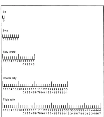
• bit, byte, word, double-word, and triple-word operations
• memory to memory operation using relative addressing on bytes, words, double-words, and triple-words
• bit operations permitting the setting, resetting, and branching on condition of a specific bit
• branch instructions which permit the comparison of two relative memory operands and branching as a result of the comparison
• addressing register operations for incrementing, decrementing, saving, and restoring addressing registers
• byte string operations for the moving of arbitrarily long byte strings from one place to another
• byte string search instructions
• buffered terminal Input/Output instructions, with selectable
1-2
• all data and program address references handled by vinual memory
• operations for the conversion of binary numbers to printable ASCII characters and vice versa
• arithmetic instructions for loading, storing, adding, subtracting, multiplying, and dividing the extended accumulator and a memory operand
• control instructions for branching, subroutine calls, and program linkage
(
The Ultimate Virtual System Architecture
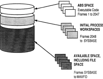
The concept of virtual memory used by Ultimate is that all data on disk, including files, is addressable by any assembly program. Any process on the system can address the entire disk in exactly the same manner. Software conventions are used to control and limit a particular process from using space that belongs to some other process, but there is no hardware enforced "memory exception" type of error.
This concept of virtual memory differs from that used by other systems where each process has its own process area and cannot address any other area and where files are not part of the addressable area.
Figure 1-1 shows a typical layout of an Ultimate virtual memory system.
Virtual memory is organized into blocks called frames. A frame is a fixed block of data resident on the disk, which can be transferred between disk and main memory. The size of a frame may vary from one hardware implementation to another, on firmware machines it is 512 bytes.
All frames are uniquely identified by a frame number, or frame-identifier (called the FID). Frame numbers start at one and continue to the last available frame in the disk set. The physical limit on the frame number is (2**24)-1, or 16,777,215. The frame numbers map directly into disk addresses.
For additional information on the Ultimate virtual memory system, see Chapter 3.
Caution! This ability to address any data in virtual memory, which
gives assembly programming its power, can also be
dangerous. Unlike BASIC, which tends to affect only the
account or terminal on which it is run, assembly programs can affect several terminals or even destroy data
1-4
ABS SPACE
Executable Code
Frames 1 to 2047
INITIAL PROCESS WORKSPACES
Frames 2048 to SYSBASE
AVAILABLE SPACE, INCLUDING FILE SPACE
Frames SYSBASE to MAXFID
Figure 1-1. Virtual Memory System
[image:24.621.185.523.93.353.2](
User Processes in a Multi-User System
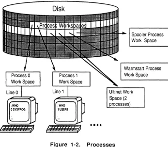
A process is an operating entity within the system that has its own functional elements and workspace. A virtual process is typically attached to a line on one of the asynchronous communication channels available on the system, and is therefore often called a channel or, more commonly in Ultimate, a port or line.
Each user interacts with the system via an assigned process line. A peripheral device connected to the line, usually a terminal, is the user's means for interaction with the system. All Ultimate systems can support one or more users at a time; the maximum number of users and/or processes that can be running at one time is a function of the system's configuration.
Note: In addition to processes that are assigned to physical lines, the print spooler and network processes are always assigned to
"phantom lines".
Figure 1-2 illustrates an Ultimate system with many processes.
Line 0
: WHO OSYSPROG
Process 1 WorkSpace
Line 1
••••
Spooler Process Work Space
Warmstart Process Work Space
[image:25.617.206.553.411.714.2]Ultinet Work Space (2 processes)
Process
Works paces
1-6
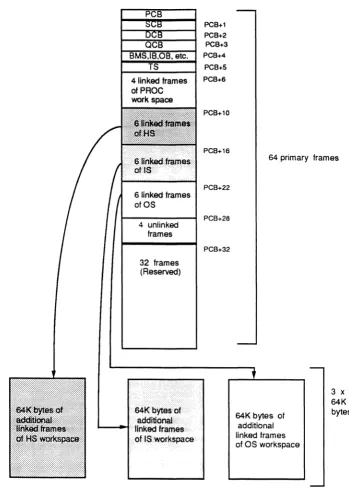
Each process has a dedicated area of virtual memory called the process workspace (see Figure 1-3). Approximately 256K bytes of workspace are reserved for each process.
The first frame of each process work space is called the Primary Control Block (PCB). The PCB is used for assembly program "housekeeping" requirements such as registers for manipulating data, stacks for program loops, and an accumulator for arithmetic functions. When a process executes an assembly instruction that references an element in this housekeeping area, the reference is always relative to the beginning of the workspace assigned to that process. This allows several processes to execute the same program simultaneously.
The format of a PCB is shown in Appendix B.
In addition to the workspace in virtual memory,each process has a dedicated block of space in main memory called the Process
Identification Block (PIB). The PIB is a fixed block of main memory that serves to define the status of a virtual process. It is used by the Kernel for process scheduling and input/output operations associated with a process, and contains all information necessary for process activation.
The PIB and its extensions constitute the only elements of a process that are always in main memory. All other information associated with a process is in virtual memory, and can remain on disk if the process is not active.
For more information about PIBs, see Appendix C.
4 unlinked frames
32 frames (Reserved)
PCB+1 PCB+2 PCB+3 PCB+4
PCB+S PCB+6
PCB+10
PCB+16
PCB+22
PCB+28
PCB+32
64 primary frames
64K bytes of additional linked frames of OS workspace
3 x 64K bytes
[image:27.613.192.541.86.575.2]The Kernel Software
1-8
The Kernel is the executive program of an Ultimate system. It is responsible for virtual process scheduling, all I/O, monitor calls, and management of memory tables.
The Kernel software differs from other assembly language software in the following respects:
• it is resident in main memory
• it is usually written in the "native" language of the machine (Honeywell Level 6, DEC LSI-ll, Motorola 68000, etc.), unlike virtual software which is written in Ultimate assembly language
• it can address any location in memory directly
All input and output (I/O) from an Ultimate system to the disk is under control of the Kernel. No other process can explicitly perform any I/O to the disk. For example, when a user process issues a write command, a flag is set in main memory to indicate that a disk write is required. The actual writing of data to disk happens at some time later as determined by the state of the memory buffer and the Kernel (and is transparent to both user and process).
At system startup, the Kernel process is used to colds tart the system. This involves loading all system software and starting up the processes that make up a multi-user computer system.
When the system is running, the Kernel is called whenever the following tasks are needed:
• process scheduling
• frame faults
• automatic disk writes
• special functions that are requested by a user process via an assembly language Monitor Call (MCAL) instruction
• terminal input/output
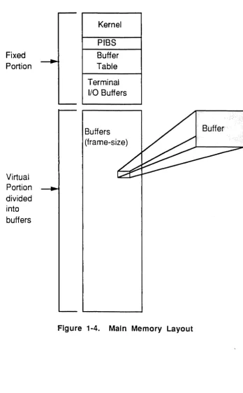
Figure 1-4 shows the main memory portion of an Ultimate computer system. Note that the fixed portion contains the Kernel software and a few other control tables (which are discussed later in this section). The
(
(
virtual portion is simply storage space to be used as needed by user processes.
Fixed Portion
Virtual Portion divided into buffers
Kernel
PIBS
Buffer Table
Terminal I/O Buffers
Buffers (frame-size)
[image:29.615.197.546.136.698.2]Process
Scheduling
1-10
A process may be active or inactive. The Kernel maintains a schedule of available processes, their current statuses (active or inactive), and their relative priority to be activated.
When the Kernel turns over control by selecting the virtual process that is next in line, with no roadblocks to prevent activation, that process is said to be active .
A process is inactive, but eligible to be activated, if it has returned control to the Kernel due to one of the following events:
• The process has executed a Monitor Call instruction. Normally, when the Kernel has completed the function that it was called upon to perform, it reactivates the virtual process immediately.
• The process was terminated by some external interrupt such as a timeslice runout.
A process is inactive and roadblocked if it has returned control to the Kernel due to one of the following events; the process will not be eligible to be activated until the roadblock is resolved:
• The process has made reference to data which is not in main memory. This causes a frame fault trap to the Kernel.
• The process has executed a READ (asynchronous channel byte) instruction when the terminal input buffer is empty.
• The process has executed a WRITE (asynchronous channel byte) instruction when the terminal output buffer is full.
• The process has executed a SLEEP and the time has not elapsed.
Assembly Language 6973-1
Confidential and Proprietary to The Ultimate Corp.
( /
Frame Faults
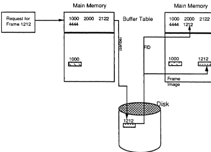
The Kernel handles disk scheduling, which involves bringing data from the disk into main memory for processing. This mechanism is called a "frame fault".Data is transferred between disk and the main memory, frame by frame (one frame at a time). Each frame is stored in memory in a block of the same size; the memory block is called a "buffer".
The FID of each frame that has been brought into memory from the disk is kept in the buffer table. Each time a frame is referenced, the system checks for its FID in the buffer table; if the FID is not there, the frame must be retrieved from disk (a "frame fault" occurs). After the frame is brought into memory, its FID is put into the buffer table.
Before the system brings the frame into memory, it checks to see if the buffer table is full. If it is full, the least recently used frame is written to disk if necessary, its FlD removed from the table, and the new FlD is added.
1-12
Request for Frame 1212
Main Memory
Request for . lOC P 2000 2122 Frame 1000 444
1000 ~
FlO in buffer table - no frame fault
Main Memory
1000 2000 2122 4444
1000 ~
Buffer Table
Buffer Table
Main Memory
1000 2000 2122 4444 1
1000 ~
1212
[image:32.621.184.525.281.526.2]FlO not in buffer table - frame fault
Figure 1-5. Frame Fault
(
(-Automatic
Disk Writes
Calls (MCAls)
from
Processes
Main Memory
Management
Periodically, such as whenever the system is idle, the Kernel attempts to "flush" memory by writing buffers to disk which have their write-required flags set This ensures that updated data is safely on disk in case of a power failure, which could destroy the contents of main memory.
If uninterrupted, the Kernel writes one or more write-required buffers at a time to disk and resets the write-required flags, until memory is
flushed. Various types of interrupts, however, such as frame faults from virtual processes, can suspend the automatic-write mechanism. During this time, the disk is kept busy reading in requested frames, and writing other frames out as needed on a least-recently-used basis. When the system again becomes idle, the automatic-write mechanism is
restarted.
The precise criteria for detennining when the system is idle is subject to variation according to configuration and operating system release.
User processes communicate with the Kernel via assembly language instructions called Monitor Calls (MCALS). Each Ultimate
implementation has its own set of MCALs that allow assembly language programmers to call the Kernel whenever any I/O functions are needed.
All I/O operations initiated at the virtual level, except those to or from the asynchronous communication channel, are accomplished through the MCALs.
The format and meaning of these Monitor calls depend on the particular Ultimate implementation being used; no details are given here.
However, standard system subroutines are provided in Section 6 for programmers to use with common devices such as tape drives and line printers (e.g., TPREAD, SETLPTR, WRTLIN, etc.).
1-14
In order to manage the main memory, the Kernel uses several tables that contain information regarding the buffers. These tables may be
accessed by memory management fIrmware as well as by the Kernel software. They are not accessible to the virtual processes.
The protection afforded to the tables is set up by the initial condition of the tables themselves. Since the memory map indicates the relationship between a disk address and a main memory location, the protected areas of memory do not have corresponding disk addresses, and therefore cannot be addressed by a virtual process.
The Ultimate operating system is configured on a wide variety of
computers. On some computers, such as the Honeywell Bull DPS-6 and various Digital Equipment Corporation (DEC) models, a ftrmware
implementation is used. On others, such as the IBM 4300 or 9370, a software implementation is used. The assembly language program source code is the same for all implementations.
A ftrmware implementation is one in which the virtual machine language is directly executed by underlying fIrmware. In addition to instruction decoding, the ftrmware also aids in virtual memory management.
A software implementation is one in which the virtual machine language is translated to the native machine language of the computer by the assembly process.
The assembly language program is assembled at the TCL level using the process referred to as the assembler. The assembler generates the machine-speciftc object code that is needed to execute the program on a given implementation. There is one assembler for ftrmware
implementations and a different assembler for each software implementation.
The Components of an Assembly Program
2-2
Assembly language programs are stored as items in disk flIes. A program is made up of assembly language instructions, as well as directives that are interpreted and used by the assembler.
An assembly instruction tells the system to perform a specific program operation, for example, move an element. An assembly directive tells the assembler to perform a specific function about the way the program is assembled (for example,. define and reserve space for symbols).
An instruction or directive must contain an operation code mnemonic (opcode), and may also contain a label, operands, and comments. Only one instruction or directive can appear on a program line. The general format is:
{label} opcode {operand{,operand ... } {comments}}
Only the opcode is required; operands may be required, depending on the instruction. Labels and comment fields are optional. One or more blanks are needed to separate label from opcode, opcode from first operand, and last operand from comments.
If a program line has a label, the label must start at the first character position in the line. If a line does not have a label, there must be at least one blank space before the opcode. A label may be composed of either alphabetic or numeric characters.
The comment field can be used to explain or document the program operation. It allows the programmer to keep a running commentary on the meaning or purpose of each line of code.
In a program item, extra blank spaces surrounding the opcode or operands in a line are ignored; however, all-blank lines or null lines are illegal.
{
Displaying the
Program
The MLIST command and the line editor AS command can be used to produce a formatted listing of the program. Figure 2-1 shows a sample excerpt from an assembly program's source code, formatted using MLIST. (For more information on MLIST, see the section, Assembler System Commands.)
! START EQU BSL BBZ MCI * LOGHDR RMBIT,RTN SM,R15 BSL INITTAPE BZ BNZ INC TCTLBSRF,RTN REJCTR,RTN INHIBITH MOV OSBEG,OS
rtn if error
mark header end in CS
tape problem tape problem
INC OS,l+ID.PWS.SZ and stay here until wrapup FAR OS,4
MOV XPFID,D8 save until wrapup MOV OSFID,RECORD
INC RECORD,-l+ID.WS.FRAMES [abt0387] MOV RECORD,XPFID
BSL RDLINK MOV OSFID,XNFID MOV SHED, MAP LOAD PRECL STORE BLOCKSIZE LOAD PROCESS# STORE CAMP# MOV OS,DECKBEG
link first to last
link last to first
get my PIB#
[image:37.612.198.554.263.655.2]Creating an Assembly Language Program
2-4
An assembly language program, also called a mode, is created using either the line editor or the screen editor. However, only the line editor provides assembly formatting.
The line editor can be set to display the lines of code in assembly listing format, using the following commands:
AS assembly listing format on/off switch; default OFF.
M macro expansion display on/off switch; default OFF. S suppress object code on/off switch; default OFF.
In addition, the following command can be used to locate a line of object code in a previously assembled mode:
QIloc#/ locates the line that contains object code location 'loc#', which is specified as a hexadecimal byte offset in the current mode (for example: 005D). Differs from Ustring/ in that only object code is searched, and the match is on a location, not a string value.
For more information on the editors, see the Guide to the U Inmate Editors.
Assembly Language 6973-1
Confidential and Proprietary to The Ultimate Corp .
(
(
(
Assembly Structures
Mode
Structure
An assembler mode item has a specific overall structure and each program line within the mode has a specific structure. The assembler program checks for this structure. In addition, the line editor uses this structure to display assembly source code lines in a standard assembly listing format, including object code, if any is present.
The assembler expects an assembly source mode to begin with comment lines. The comments may use as many lines as needed. Following the initial comments, the assembler looks for the beginning of the Entry Point Branch Table, followed by the directives that are used to define symbols and registers in the program. This section of the program is then followed by the main program instruction routines. This structure is similar to the following:
001 FRAME directive.
002 * Comment line.
003 * Comment line.
004 * Comment line.
005 * Comment line.
006 * Comment line.
Onn entry point 1
By convention, program type/purpose.
assembler places current system date
By convention, these lines contain
revision level, author, and other
explanatory comments.
nnn final entry point
xxx symbol definitions
yyy main program
zzz END
Each of these elements is discussed on the following pages.
2-6
FRAME Directive
The FRAME directive specifies the frame in which this program mode is to be loaded. FRAME also sets the assembler's location counter to I or 2, depending on the implementation. You may use an ORG directive to reset the location to ORG 0 if you wish to use the first 1 or 2 bytes.
The frame number must be within the limits for ABS frames. For release 200, the limits are frame 0 to frame 2047. In general, user-written code should be loaded into frames 400-599; Ultimate reserves these frames for user modes. It is possible that other user modes and applications already have used some of these frames, so be sure to check that the frame is free before using it.
No Ie: The USER-MODES file in the SYSPROG account contains user
modes that are loaded by the COW-START PROC. This is a
good starting point in detecting used program/rames.
Comment lines
A comment line is defined by an asterisk (*) in column 1 or by the
CMNT directive. The
*
comment line has no tabbing performed; it is one long line of text comments. The CMNT directive must be in column 2 or beyond; everything else on that line is considered to be comments. ACMNT directive may be preceded by a labeL
N
ole:
The assembler puts the system date in line 3 onlyif
it is a comment line that begins with an *.Entry Point Branch Table
This is a sequence of up to 16 Entry Point (EP) instructions that defines the entry points (numbered 0-15) into the mode. The entry points may be given sequential labels such as 0, 1, 2, etc., or alpha labels. (For information on using the entry points to execute the program, see Chapter 6.)
The entry points must be the first instructions that generate object code.
(
c
Modeids
-External
Program
References
By setting the entry points up as a series of branches, you can later change the program and reassemble it without affecting the entry points.
Note: Although no entry points are required to be defined after the
last used entry point, it is usually safer to put NEP instructions
in place of all unused entry points.
All assembly language programs to be executed must be identified by a mode-id in order for the system to access the correct frame (Fill) and entry point in memory where the program is located.
A mode-id is a 16-bit field (that is, it fits in a tally), and is composed of one hex digit for the entry point and three hex digits for the frame number (Fill). Together these make up an address to which execution control can be transferred in a program.
Every program needs to have a defined mode-id; however, the mode-id is actually stored in different places, depending on the system interface being used to initiate the program:
• If the program is to be executed as a verb (system command) from TCL, the mode-id is stored (in ASCII character format) in the verb definition item in the Master Dictionary (MD) of each account that runs the program.
• If the program is to be executed via the CONY (Conversion) interface, the mode-id is given as part of the 'Unxxx' conversion code in the
BASIC ICONV or OCONV function that calls it. If the program is associated with Recall attributes, the mode-id is given in the 'Unxxx' (User Exit) Correlative or Conversion code (line 7 or 8) in a
dictionary attribute definition item.
• If the program is to be executed from PROC, the mode-id is given as part of the 'Unxxx' or 'Pnxxx' PROC command that calls it.
In all 'Unxxx' specifications, the 'nxxx' is four hexadecimal digits of mode-id, which immediately follow the 'V' conversion code letter. 'Unxxx' means entry point 'n' (O-F) of frame 'xxx' (I-FFF, which is 1-4095 in decimal). For more information on BASIC, Recall, and PROC, please see the appropriate reference manual.
2-8
above 1023, especially, are typically used for purposes other than assembly programming.
In assembly language programming, when a program needs to branch to an entry point in another frame, a symbol should be predefined as a mode-id that points to the desired entry point in the desired frame. If a symbol already exists in the PSYM file which defmes this mode-id, then that symbol may be used. Otherwise, both the entry point and FID of the mode-id should be explicitly specified in the calling program.
A mode-id may be defined in two ways:
• DEFM directive (defines a symbol; no object code)
• M1L Y or M1L YU directive (defines a symbol and reserves storage, word-aligned only if MTL Y)
The DEFM method may be used to simply define a synonym for a location already allocated storage (or that will be allocated storage before the program calls it). For example, the following defines the symbol EXT.SUB as a mode-id whose value is entry point 4 in frame 500:
EXT. SUB DEFM 4,500
EXT.SUB may then be used as an operand in instructions such as the following:
BSL EXT. SUB
ENT EXT. SUB
Call external subroutine
Branch with no return
The M1L Y directive should be used when storage needs to be reserved.
M1LY and M1LYU are less frequently used, except when constructing tables of mode-ids. For example:
EXT. SUB MTLY 4,500
LOAD EXT. SUB
BSLI *
CMNT *
Assembly Language
Get mode-id in accumulator
Call subroutine referenced
by accumulator
Program Line
Structure
A source line may contain up to five fields of infonnation:
• label field
• source code operation field (opcode mnemonic)
• source code operand field
• comment field
• object code generated by assembler
Label field
The optional label, if present, must begin in column 1 of an input line and must begin with an alphanumeric character. Labels may be up to 50 characters in length, although only 10 columns are reserved for the format on an assembly listing.
Labels should not contain an asterisk (*), a slash (/), or a plus sign (+).
A label is separated from the opcode mnemonic by a space.
Labels are locally defined symbols used to address locations in the program, or to defme other symbol types. A label must be used as the target of all branch instructions (conditional or unconditional).
Examples are:
LOOP
!STARTIT
TOTAL-X
TEST123
Opcode field
The opcode is separated from the label and the operands by at least one space. If there is no label, at least one space must precede the opcode.
Opcodes may be primitive or macro instructions, or directives. They consist of the opcode mnemonic and usually one or more operands. Examples of mnemonics are:
2-10
INC
BSL
The valid opcodes are described in Chapter 4.
Operand field
The operands are separated from the ope ode by at least one space. Multiple operands are separated by commas, and no spaces are allowed within the field (except in quoted character literals). Operands may be literals, symbols, or the current location counter, using the forms shown below:
Form Description
C'xxxx' Text string; example:
e'NOT AGAIN'
If a single quote (') is needed as a literal, two adjacent single quotes must be used; example: for JOE'S, use the operand
e'JOE" s'
For just a single quote, use
e""
n Decimal integer; examples: 120 or -42
X'xxxx' Hexadecimal constant; example: x' FE' or
X'8100FF'
If an odd number of hex characters is used, a leading zero is assumed to fill the leftmost nibble
symbol Symbol name predefined in the PSYM file or defined in the label field of the source program
* Current byte location in frame; uses the
assembler program location counter to return the first byte of the current location or address being assembled
*n Current location in units of 'n' bits; examples: *1
=
loco in bits; *8=
*; *16=
loco in words This location counter advances as instructions are assembled; the counter can be altered only via an Origin (ORG) directive.literals +/-loc Literals or * locations combined with a plus (+)
or minus (-). Symbols cannot be used here; examples:
*+2
*-1
Displaying
Assembly
Programs in
the Editor
2-12
Comments field
The optional comments field follows the last operand, separated by at least one space, and may be of any length.
Object Code field
The first four columns of the object code field contain the byte offset (displacement) in the frame, followed by a space, followed by the actual object code. The object code is separated from the source code by a subvalue mark, placed there by the assembler.
The line editor has three commands that can be used to display assembly language programs:
AS displays source code in pre-sized fields
M displays macro expansions
S suppresses object code (if any) in object field
Source code lines may be displayed on the screen with all fields shown when the Editor is used with the assembly listing switches AS and M
turned on and S turned off.
If both the AS switch and the
s
switch are off, each line is displayed as entered. Macro expansions and error messages, if any, follow the source code and are separated from it by value marks. Object code, if any, follows the source code and any macro expansion code; it is separated by sub-value marks. For example,013 SAVE MCC R4,R5 MOVE THE TERMINATOR\0056 645D 014 MCC R4,R16 SAVE IT ALSO]*ERR: REF:UDEF, REF:UDEF 015 B OK] B: OK\0058 lE45
(
(~
" " / '
When AS is on, the assembly listing fonnat is as follows:
Col 1-15 16 17-25
26
27-31 32 33-49 50 51-75Field description
object code
blank
label field; contains one of the following: label
*
(comment line)(null) neither label nor comment
blank opcode field blank operand field blank comment field
The following example shows a program in the editor with AS on, but with S and M off (the editor item line numbers are shown to the left of the program line itself).
column: 1 2 3 4 5
1234567890123456789012345678901234567890123456789012_.
001 0001 7FF001D7 FRAME 471
002 * SAVE/RESTORE
003 *24 APR 1990
013 0000 ORG 0
014 0000 FE CHR AM
015 AM EQU R1
016 *
017 0001 1E27 0 EP !LOG
018 0003 1E38 1 EP !CMDLOOP
073 0028 !LOG EQU *
074 0028 A00200 ZERO PRMPCH
085 0049 1172B2 B CMD200
2-14
If S is on (suppress object code), lines 13-18 would list as:
1 2 3 4 5 1234567890123456789012345678901234567890123456789012_ 013 ORG 0
014 CHR AM 015 AM EQU R1 016
*
017 0 EP !LOG 018 1 EP !CMDLOOP
If M is also on (display macro expansions), line 85 would list as:
085 B CMD200 +B: CMD200
(
The Assembler Program
The assembler translates source code statements into object code. The source mode may be stored as an item in any fIle. In firmware
implementions, the object code is assembled in place; that is, at the conclusion of the assembly process, the item contains both the original source code and the generated object code. In software implementations the destination of the object code must be specified; it can be a separate fIle or it can be in the current file.
The assembled object code must be less than or equal to one ABS frame in size. On all machines the operative frame size is stored in the PSYM file as the symbol ID.ABSFRM.SIZE; on firmware machines, this is 512 bytes.
Each implementation has its own version of the assembler and is invoked as follows:
fmnware systems use the AS verb
s/370 systems
1400 systems
use the OPT verb.
use the ASM verb
When a program is assembled, the generated object code is stored along with the source statement and system delimiters are used to separate the components on each line. On fmnware machines, the object code is stored back into the source file. On 1400 and s/370 systems, it is stored a separate fIle. On a fmnware system, while you are editing an already assembled program, you can ignore any data beyond the source
statement, because the assembler examines only the source data on each line as it performs the assembly; any existing object code and other characters are discarded.
Listing
Assembled
Programs
2-16
The following system commands can be used to generate listings using an assembled program item:
MLIST generates a fonnatted listing
MLOAD
MVERIFY
loads the program for execution
verifies the loaded code
CROSS-INDEX generates concordance listings
X-REF generates a cross reference by symbol name
XREF enhanced version of X-REF
These system commands are described in in this chapter in the section, Assembly Program Listings.
Executing Assembled Programs
An assembled program is not automatically ready to execute. In order to run an assembled program, you must create a verb definition item in the account's Master Dictionary (MD), or call the program from BASIC, PROC, Recall, or another assembly language program.
The following interfaces can be used between user-written programs and the Ultimate operating system. Each interface is designed for a particular function or type of program.
Interface Function
CONY For subroutine calls from BASIC or Recall. Used when a conversion needs to be perfonned.
PROC For routines called from PROC.
RECALL For verbs that use Recall's data base reponing capabilities.
TCL-I For verbs that use the TCL-I fonn (no filename)
TCL-II For verbs that use TCL-II fonn (filename).
WRAPUP For exiting verbs, or anywhere if a program may exit on an error condition.
XMODE For handling Forward Link Zero register
conditions (that is, to add frames to a linked set during program operation).
When an assembled program is ready for production, the appropriate interface must be selected and programmed. Most user-written programs use the TCL-I, TCL-II, or the CONY interfaces. The TCL interfaces involve defining the program as a verb in the MD. Once the verb defmition is stored, the program can be executed by entering the verb name at the TCLor specifying the name anywhere a system command is valid.
The AS Command - Firmware Assemblies
Syntax
Description
2-18
The AS command is used to assemble programs for a fmnware machine.
AS filename {itemlist} {(options)}
filename name of fIle that contains items to be assembled
itemlist names of items to assemble; may be one or more explicit item-IDs, or an asterisk (*) to specify all items in the file; may be omitted if a select-list is active
(options the following options are available:
E when used in conjunction with the L option, lists only errors
L generates a listing equivalent to the MLIST command during assembly
N inhibits waiting at end-of-page during listing to terminal; useful in conjunction with
z
optionP routes output to print spooler
Q specifies that messages are not to be displayed nor the editor entered if assembly errors are found; normally, this is used when multiple items are being assembled
Z specifies that, if assembly errors are found, the editor is not to be entered; normally, this is used when multiple items are being assembled
The AS command requires three files to be defined on the user's account:
OSYM opcode symbol fIle; contains all the opcodes and valid symbol types for each opcode
PSYM permanent symbol file; contains the global symbols available to all assembly language programs
TSYM temporary symbol file; used by the assembler to store the symbols used in the mode currently being assembled
OSYM and PSYM are typically Q-pointers to the Ultimate-supplied OSYM
and PSYM fIles, but TSYM must be created for each account. For more information on the symbol flies, see the section, Symbol Files.
(
('
Only one user at a time in an account can use the AS command.
The AS command is table driven and performs two passes over the source code. During the first pass, all instructions that have undefmed and forward references are flagged as requiring re-assembly. Local labels are stored in the temporary symbol flle (TSYM) during this first pass, along with the literal definitions that need to be created.
As the assembler processes items, it outputs an asterisk (*) after every ten source statements are assembled. At the end of the first pass, the literals are generated and added to the end of the current object code.
On pass two, a new line is started and an asterisk is printed for each ten statements reassembled.
If there are any assembly errors, the assembler enters the editor so that the program may be conveniently corrected for reassembly (unless suppressed by the Q or Z option).
If there are no errors, the following message is displayed (unless the Q
or Z option is used):
[236] No errors
The AS command is table driven and performs two source code passes:
I . In the first pass, all instructions haveing undefined and forward references are flagged as requiring re-assembly. Local labels are stored in the temporary symbol file (TSYM), along with the literal definitions that need to be created. At the end of the first pass, the literals are generated and added to the end of the current object code. As the Assembler processes items, it outputs an asterisk (*) after every 10 source statements assembled.
2. In pass two, a new line is started and an asterisk is printed for each 10 statements reassembled.
Assembly errors cause the Editor to be entered for program correcttion for reassembly (unless suppressed by the Q or Z option). If no errors, the following message displays (unless the
Q
or Z option is used):2-20
Assembler error messages are stored as part of the source line in error. Undefined symbols are stored as a message list in the last line of source. Assembler error messages are explained below.
Message
OPCD? OPRNDREQD ILGL opeD: xxxx
LBLREQD
MUL-DEF OPRND DEF
OPRNDRNGE
REF:UDEF
TRUNe
UNDEF: xxx {,xxx .. }
:AS SM PROGl
******************
***
[236] No errors
Assembly Language
Description
opcode mnemonic is missing
instruction is missing at least one operand
either the opcode mnemonic, or operands specified are not valid for this opcode
an Equate (EQU) directive does not contain a symbol in the label field, so there is nothing to equate the value to
label is defined more than once
either the operand is defined improperly or is not valid for this instruction
operand's numeric value is not within the valid range for this instruction
instruction references an undefined symbol
an operand is out of range. Typically this error occurs when a program exceeds the size of a frame and an instruction tries to reference an Assembler-generated literal beyond the last location of an ABS frame
list of undefined symbols found
(pass 1 output from assembler) (pass 2 output from assembler)
(
The OPT Command -
S/370 Assemblies
Syntax
Description
(
('~
The OPr command is used to be assemble a program for s/370
implementations of the Ultimate Operating System. The command itself is a cataloged BASIC program and is included in the SYSPROG account.
OPT
filename {itemlist}
{(L}filename
name of file that contains items to be assembleditemlist
names of items to assemble; may be one or more explicit item-IDS, or an asterisk (*) to specify all items in the file; may be omitted if a select-list is active(L generates an instruction that allows a BREAK at each label.
Note: Once a program has been debugged, it should be assembled
without the L option in order to run more efficiently.
OPT requires the following symbol files to be defined on the account doing the assembly:
Il.PSYM pennanent symbol file used in pass I of the assembly
Il.OSYM opcode symbol file used in pass 1 of the assembly
IPSYM pennanent symbol file used in pass 2 of the assembly
IOSYM opcode symbol file used in pass 2 of the assembly
ISM file used by the assembler to store assembled object code; must be created by user
TSYM temporary symbol file; used by the assembler to store the symbols used in the mode currently being assembled. This file must be created with a data section modulo of 31.
The Il.PSYM, Il.OSYM, IPSYM and IOSYM files are delivered on the SYSPROG account. To assemble from another account, Q-pointers should be set to the file in the SYSPROG account.
The OPT command uses the following two verbs, which must be defined on the account doing the assembly:
AS.IBM
2-22
The OPT version of the assembler makes two passes. Pass I converts the Ultimate source code to s/370 source code. Pass 2 assembles the s/370 source code into s/370 object code.
When the assembly is complete, the following message is displayed:
[206] 'itemname' assembled
The object code is stored in the ISM file under the item name used in the assembly. If there were errors or undefined references, these are also stored in the item in the ISM file.
Each assembled item should be edited to determine if errors exist. The following shows an assembled item with errors:
*ERR MOV BMS, 15
*ERR: ILGL opeD: MOV:RN
(
(
"('~'
The ASM Command - 1400 Assemblies
Syntax
ASM is used to assemble a program for 1400 implementations of the Ultimate Operating System. The command itself is a cataloged BASIC
program.
ASM fIlename {item-ist} {(options)}
filename name of fIle that contains items to be assembled
itemlist names of items to assemble; may be one or more explicit item-IDs, or an asterisk (*) to specify all items in the fIle; may be omitted if a select-list is active
(options the following options are available:
C retains comment lines from the source code instead of suppressing them from the assembled program. By default,
ASM deletes comment lines in the source, and converts source code into comment lines; the assembled code is indented beneath the source code that generated it. With the
c
option, a comment line is converted as a comment with a greater-than sign (that is, It*> comment-textlt) .
E when used in conjunction with the L option, lists only errors
L generates a listing equivalent to the MLIST command during assembly.
N inhibits waiting at end-of-page during listing to tenninal; useful in conjunction with Z option.
p routes output to print spooler.
Q specifies that messages are not to be displayed nor the editor entered if assembly errors are found; nonnally, this is used when multiple items are being assembled
V inserts a V.TRAP instruction into the native code before each source instruction instead of just at labels. By default, ASM
Description
2-24
N
ole:
Once a program has been debugged, it slwuld be assembled witlwut the V option in order to run efficiently.Z specifies that the editor is not to be entered if assembly errors are found; normally, this is used when multiple items are being assembled
ASM requires the following symbol files to be defmed on the user's account:
M1.0SYM
Ml.PSYM
M2.0SYM
M2.PSYM
opcode symbol file; used by pass 1 of the assembler program to convert Ultimate assembler code to 1400 assembler code
permanent symbol file; contains all predefined symbols available to the assembly language programmer
opcode symbol file; used by pass 3 of the assembler program to convert 1400 assembler code to object code
permanent symbol file; used by the assembler program
OPT.ERRORS optimizer errors; used by optimizer to store errors encountered during pass 2
TSYM temporary symbol file; used by the assembler to store the symbols used in the mode currently being assembled
The symbol files are described in the section, Symbol Files.
The OPT command uses the following two verbs, which must be defined on the account doing the assembly:
ASMI
ASM2
When ASM is invoked, it first prompts for a destination file name:
To: {(filename) {item-list}
The response to the To: prompt may be a filename or item-IDS or both; pressing RETURN with no response cancels the ASM command. All destination filelitem name forms that are valid for a COpy command may be used. For example:
(,
ASM BP
*
TO: (BD
assembles all items in the BP source fIle to the BD fIle using the same item-IDS as in BP. Another example:
ASM SSM T
To:T.OBJ
assembles one item in SSM to the same file as item 'T.OBJ'.
After a valid destination fIle has been specified, the ASM command starts the assembly.
ASM uses three passes:
I. Executes the ASMI verb, which assembles virtual code into native machine source code, using M1.0SYM and M1.PSYM.
2. Executes a BASIC program in the SYSPROG-PL file called OPT. The symbol fIles are used to construct the destination file items. Any errors encountered are logged in the OPT.ERRORS fIle, described below. The optimized items are output to the specified destination file.
3 . Executes the AsM2 verb, which assembles the object code, using the output of the optimizer and the M2.PSYM and M2.0SYM symbol fIles. The items are updated in the destination file.
This sequence is looped through for all items in the list.
The Optimizer
Object code for an assembled item must fit into one ABS frame. If the object code generated by the optimizer in pass 2 does not fit in an ABSframe in the first try, the optimizer reassembles the code using a compression algorithm. Level 0 is "no compression"; level 9 is "maximum compression". The higher the compression level, the
2-26
Each level of compression specifies which instructions are to be
compressed by the optimizer. An instruction is compressed by moving most of its code to the Kernel, leaving only code to set up a call to the Kernel in the assembled object code.
The level of compression for a program is stored in attribute 2.of the destination item in the following format:
002 * compression level = n
n number of iterations used by the Optimizer to get the object code to fit into an ABS frame
If the destination item already exists, the value in attribute 2 is used as the compression level for the program being assembled. The Optimizer does not reduce the compression level value previously stored. This means that even if code has been removed to make the program smaller, the optimizer starts the assembly at the previous level of compression. To overcome this restriction, you should either delete the old destination item, or edit the old item and set the compression level back to 0 before reassembling the program.
The OPT.ERRORS File
This file contains an item for each source file item that has been
assembled. OPT. ERRORS stores the time and date of the assembly in the item, as well as any errors that the optimizer found while processing the source file item.
(~'
Assembler Error Messages
(
Assembly error messages are stored as part of the source line in error.
If undefined symbols exist, a list of these symbols is stored as a
message in the last line of source. If any assembly errors are found, the Editor is called as a convenient way to edit the source item, unless the Q or
z
option was specified with the assembler command.Message Description
OPCD? The opcode mnemonic is missing.
OPRNDREQD The instruction is missing at least one operand.
ILGL OPCD: xxxx Either the opcode mnemonic is not valid, or the operands specified are not valid for this opcode.
LBLREQD An Equate (EQU) directive does not contain a
symbol in the label field, so there is nothing to equate the value to.
MUL-DEF The label is defined more than once.
OPRNDDEF Either the operand is defmed improperly or
is of an invalid type for this instruction.
OPRNDRNGE The operand's numeric value is not within
the valid range for this instruction.
REF: UDEF The instruction references an undefined
symbol.
TRONC An operand is out of range; typically this
occurs when a program exceeds the size of a frame and an instruction tries to reference an assembler-generated literal beyond the last location of an abs frame.
UNDEF:xxx List of undefined symbols found.
OSYM Errors
2-28
The following error messages are issued when the assembler detects errors in the OSYM file defmitions:
FRMT. A-FIELD
FRMT. B-FIELD
OPCD TYP
MACRO DEF
# MOD WORDSIZE > 32 BITS EXIT DEFN
To correct the OSYM file, perform a selective restore (SEL-RESTORE command) of the OSYM file using the latest SYSGEN tape.
(
(
Generating Object Code
Directives and
Object Code
Instructions
and Object
Code
The output of the assembly procedure is object code that the Ultimate machine can direcdy execute. The actual object code on Ultimate software implementations depends on the native code of the system; however, all firmware machines generate the same object code.
The assembly procedure performs two distinct tasks on source code, determined by the type of operation:
• directives are processed to set up the program structure and generate object code where needed
• instructions are assembled into object code
Directives do not generate executable code. They may, however, generate object code in the sense that symbol defmitions may reserve space in the program frame and may also assign a value which is in "object" format.
The following directives do generate object in that sense:
ADDR ALIGN DTI.Y FrLY H1LY MTI.