Thank you for using ArmyStudyGuide.com. Free Online U.
S. Army Board Study
Guide
Other Sections: Cadences Counseling PowerPoint Leaders Book SMCT (CTT)
Schools Prep For Basic
Online Since 1999
Print Study Guide Home
Forum Tell a friend
Prepare for boards Promotion Points Add A Shortcut
Site Sponsor
Other Sections
Counseling Help Prepare for Basic PowerPoint Help Cadences
Army Schools Games
SMCT SL 1,2,3,4 Leaders Book Info Audie Murphy Expert Infantry Exp. Field Medical Drill Sergeant Army Recruiter
Advertise Here!
You are here: Home > M203 >
Choose A Study Guide Subject: .
M203 Information
Weight:
Launcher: 3 pounds (1.36 kilograms)
Rifle (M16A2): 8.79 pounds (3.99 kg)
Total (including 30 rounds): 11.79 pounds (5.35 kg)
Bore diameter: 40mm
Maximum effective range:
Area target: 1148.35 feet (350 meters)
Point target: 492.15 feet (150 meters)
Maximum range: 1312.4 feet (400 meters)
Minimum safe range:
Training: 426.53 feet (130 meters)
Combat: 101.71 feet (31 meters)
Unit Replacement Cost: $601
Features: The M203 40mm Grenade Launcher is used while attached to an M16A2 5.56mm rifle. It is a lightweight, compact, breech loading, pump action, single shot launcher. The launcher consists of a hand guard and sight assembly with an adjustable metallic folding, short-range blade sight assembly, and an aluminum receiver assembly which houses the barrel latch, barrel stop and firing mechanism. The launcher is capable of firing a variety of low velocity 40mm ammunition.
The launcher also has a quadrant sight which may be attached to the M16A2 carrying handle and is used when precision is required out to the maximum effective range of the weapon.
Background: The M203 was designed and procured as the replacement for the M79 grenade launcher of the Vietnam era
Thank you for using ArmyStudyGuide.com. Free Online U.
S. Army Board Study
Guide
Other Sections: Cadences Counseling PowerPoint Leaders Book SMCT (CTT)
Schools Prep For Basic
Online Since 1999
Print Study Guide Home
Forum
Cadences
Games
The four fundamentals of M203 marksmanship are steady position, aiming, breathing, and trigger control. When the soldier changes his position, only the first fundamental (steady position) varies. The other three remain the same.
a. Steady Position. This varies according to the position.
(1) Prone position. If you fire prone, try to use a prone supported position (Figure 5-1).
(a) Lie face down, grasp the M16 pistol grip with your right hand and place the butt of the rifle into the pocket of your right shoulder.
(b) Lower your right elbow to the ground so your shoulders are level. This places the weight of your body behind the weapon, which enables you to recover quickly each time you
so your heels will rest on the ground. Relax the weight of your upper body forward onto your left arm.
(d) For ranges greater than 150 meters, lower the buttstock of the weapon to obtain the proper sight alignment and sight picture. Grip firmly to prevent this from moving the weapon from your shoulder pocket.
WARNING
ENSURE THE SLING IS CLEAR OF THE WEAPON MUZZLE BEFORE FIRING. >
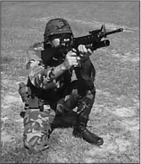
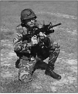
(2) Kneeling position. Figure 5-2 shows the kneeling position.
(c) Keeping your right toe in place, sit on your right heel.
(d) Place your left elbow forward of your left knee, resting the flat portion of your upper arm on your knee.
(e) Move the rifle butt into the pocket of your right shoulder, pulling the rifle pistol grip with your right hand.
(f) With your left hand on the rifle magazine, place your left forefinger in the trigger guard of the grenade launcher.
(g) Pull the rifle firmly into your shoulder.
(h) Pull your right elbow in close to your body to help you apply rearward pressure to the weapon. Ensure that your leg completes a solid, three-point base for your position. For ranges greater than 150 meters, lower the buttstock of the weapon to obtain the proper sight alignment and sight picture. Grip firmly to prevent this from moving the weapon from your shoulder pocket.
position--(b) Grasp the rifle magazine with your left hand and the pistol grip with your right hand.
(c) Bend forward from your hips, and rest your left upper arm against the inside of your left knee.
(d) Move the butt of the rifle into the pocket of your right shoulder, still holding the rifle pistol grip with your right hand.
(e) Rest your right elbow on the inside of your right knee.
(f) Pull the weapon down slightly with your left hand, and pull it to the rear firmly with your right hand.
(g) For ranges greater than 150 meters, lower the buttstock of the weapon to obtain the proper sight alignment and sight picture. Grip firmly to prevent this from moving the weapon from your shoulder pocket.
(4) Sitting position, cross-ankled. Figure 5-4 shows the cross-ankled sitting position. To assume this
(a) Sit facing the target half right.
(d) Grasp the rifle magazine with your left hand and the rifle pistol grip with your right.
(e) Place your left upper arm across your left knee.
(f) Move the butt of the rifle into the pocket of your right shoulder.
(g) Lower your right elbow so that your upper right arm is in contact with your right knee.
(h) For ranges greater than 150 meters, lower the buttstock of the weapon to obtain the proper sight alignment and sight picture. Grip firmly to prevent this from moving the weapon from your shoulder pocket.
(5) Sitting position, cross-legged. Figure 5-5 shows the cross-legged sitting position. To assume this
(a) Sit down facing the target half right.
(b) Cross your left leg over your right leg, and draw both feet close to your body.
(f) Lower your right elbow so that your right upper arm is against your right knee.
(g) For ranges greater than 150 meters, lower the buttstock of the weapon to obtain the proper sight alignment and sight picture. Grip firmly to prevent this from moving the weapon from your shoulder pocket.
(6) Squatting position. Figure 5-6 shows the squatting position.
(a) Turn half right to the target, and with your feet a
comfortable distance apart, squat as low as you can, keeping both feet flat on the ground.
(b) Grasp the rifle magazine with your left hand.
(c) Place your left upper arm inside your left knee and the butt of the stock into the pocket of your right shoulder, then grasp the rifle pistol grip properly.
(d) Lower your right elbow against the inside of your right knee.
(7) Fighting position. If you fire from a fighting position, try to use support (Figure 5-7).
(a) Place your right foot against the rear of the fighting position, then lean forward until your chest is against its forward edge.
(b) Grasp the magazine with your left hand.
(c) Place your left elbow on or against solid support.
(d) Use your right hand to position the butt of the stock in the pocket of your right shoulder, then grasp the rifle pistol grip properly.
(e) Place your right elbow on or against a solid support, and relax into a comfortable firing position.
(f) For ranges greater than 150 meters, lower the buttstock of the weapon to achieve proper sight alignment and sight
picture. Grip firmly to prevent this from moving the weapon from your shoulder pocket.
NOTE:
(a) Face the target standing, and spread your feet a comfortable distance apart.
(b) Grasp the rifle pistol grip with your right hand and the rifle magazine with your left hand. Then place the butt of the stock into your right shoulder so that the sight is level with your eyes.
(c) Hold your right elbow high to form a good pocket for the butt of the stock and to permit a strong rearward pressure with your right hand.
(d) Hold most of the weight of the weapon with your left hand.
(e) Shift your feet until you achieve a natural aiming stance.
b. Aiming. Aiming procedures for every position are as follows:
(1) Aligning sight. When using the leaf sight, align it with the front sight post of the M16. When using the quadrant sight, align its rear sight aperture with its front sight post. Picture a horizontal line through the center of the leaf sight or rear sight aperture. The top of the M16's front sight post should touch this line. Picture a vertical line through the center of the leaf sight or rear sight aperture. This line should vertically dissect the front sight post (Figure 5-9).
(2) Focusing. For either sight, focus on the front sight post; a good firing position places your eye directly on line with the center of the leaf sight or rear sight aperture. Your eye's natural ability to center objects in a circle and seek the point of greatest light will help you align the sight correctly.
(3) Obtaining sight picture. To achieve a correct sight picture, align the front sight post and leaf sight or rear sight aperture with the target. For area targets, aim where the round's bursting radius will make the round most effective. For point targets, aim at the target's center of mass.
c. Breathing. The technique for breathing is the same for every position: Breathe naturally. Exhale most of your air, hold your breath, and fire before you become uncomfortable. In combat, just choke off your breath before firing.
d. Trigger Control. The technique for trigger control is the same for every position. Place your trigger finger (the index finger of your left hand), between the first joint and the tip of your finger (not at the
40-MM
GRENADE LAUNCHER,
M203
FEBRUARY 2003
DISTRIBUTION RELEASE: Approved for public release; distribution is unlimited. ________________________________
FIELD MANUAL HEADQUARTERS
NO. 3-22.31 DEPARTMENT OF THE ARMY
Washington, DC, 13 February 2003
40-MM GRENADE LAUNCHER, M203
CONTENTS
Page
PREFACE... iv
CHAPTER 1. INTRODUCTION
1-1. Training Strategy ... 1-1 1-2. Combat Conditions ... 1-2
CHAPTER 2. OPERATION AND FUNCTION
2-1. Operation ... 2-1 2-2. Loading ... 2-1 2-3. Unloading... 2-2
2-4. Cycle of Functioning ... 2-3
CHAPTER 3. DESCRIPTION AND MAINTENANCE
3-1. Description... 3-1 3-2. Technical Data ... 3-3 3-3. Components ... 3-4 3-4. Ammunition ... 3-7 3-5. Clearing Procedures... 3-13 3-6. General Disassembly ... 3-13
3-7. Cleaning and Lubrication... 3-15
3-8. Inspection... 3-16 3-9. General Assembly... 3-16
3-10. Care and Handling ... 3-18 3-11. Care and Handling Under NBC Conditions ... 3-19
3-12. Decontamination... 3-19
CHAPTER 4. PERFORMANCE PROBLEMS AND DESTRUCTION
4-1. Malfunctions ... 4-1 4-2. Stoppages ... 4-1 4-3. Immediate Action ... 4-2 4-4. Remedial Action ... 4-3
Page
4-5. Destruction Procedures ... 4-3
CHAPTER 5. MARKSMANSHIP TRAINING
Section I. Preliminary Marksmanship Training
5-1. Four Fundamentals of Marksmanship ... 5-1
5-2. Limited Visibility... 5-18 5-3. NBC Environment ... 5-20 5-4. Fire Commands... 5-20 5-5. Dry-Fire Exercises ... 5-21
5-6. Sensing and Adjustment of Fire... 5-22 5-7. Grenade Launcher Range Layout ... 5-23 5-8. Description of Range and Targets ... 5-23 Section II. Basic Gunnery
5-9. Zeroing the M203 Grenade Launcher... 5-24 5-10. Overall Qualification Standards... 5-26 5-11. Day Record Fire... 5-28 5-12. Day Record Fire Qualification Standards... 5-31 5-13. Mounting the AN/PVS-4 (Without the Rail System) ... 5-32 5-14. Zeroing the AN/PVS-4 to the M203... 5-33 5-15. Night Record Fire ... 5-36 5-16. Night Record Fire Qualification Standards ... 5-37
CHAPTER 6. COMBAT TECHNIQUES OF FIRE
Section I. Advanced Gunnery
6-1. Characteristics of Fire... 6-1 6-2. Classes of Fire... 6-1
6-3. Range Estimation... 6-4 6-4. Predetermined Fires ... 6-6
6-5. Types of Targets ... 6-7
6-6. Decontamination... 6-9 Section II. Fire Control
6-7. Methods of Fire Control ... 6-10
6-8. Fire Commands... 6-12 Section III. Application of Fire
6-9. Suppressive Fire... 6-16 6-10. Overwatch Fire ... 6-16
6-11. Area and Point Fire ... 6-16
6-12. Target Engagement ... 6-17 6-13. Limited Visibility... 6-18 6-14. Overhead Fire ... 6-18
CHAPTER 7. TRAIN-THE-TRAINER PROGRAM
Section I. Organization
Page
7-4. Assistant Trainers and Cadre Coaches... 7-2
7-5. Command Benefits ... 7-3 7-6. Program Phases... 7-3 Section II. Training Tasks
7-7. Phase I, Preliminary Marksmanship Instruction... 7-3 7-8. Phase II, Basic Gunnery... 7-5 Section III. Trainers’ Certification
7-9. Training Base... 7-6 7-10. Certification Outline ... 7-6
APPENDIX A. 40-MM GRENADE LAUNCHER, M79... A-1
APPENDIX B. UNIT TRAINING PROGRAM ...B-1
APPENDIX C. PROFICIENCY (PERFORMANCE) EXAMINATION...C-1
APPENDIX D. RANGE SAFETY... D-1
APPENDIX E. STANDARDS, STRATEGIES, AND REQUIREMENTS ...E-1
GLOSSARY... Glossary-1
REFERENCES... References-1
PREFACE
This manual provides technical information on and training and combat techniques for the M203 grenade launcher. Intended users include leaders and designated grenadiers, who will use this information to successfully integrate the M203 into their combat operations. This manual discusses gunnery training and train-the-trainer and includes an appendix on the 40-mm grenade launcher, M79.
The tactical positions shown in this manual were drawn to enhance the reader’s understanding of related subject material and are not tactically correct.
Unless stated otherwise, masculine nouns and pronouns in this publication do not refer exclusively to men.
CHAPTER 1
INTRODUCTION
This chapter discusses the training strategy and combat conditions for the 40-mm grenade launcher, M203. (Appendix A discusses the M79 model.)
1-1. TRAINING STRATEGY
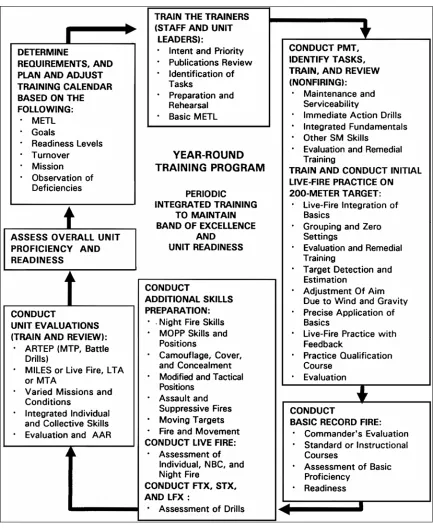
An effective overall training strategy produces well-trained grenadiers and trainers by integrating resources into an effective year-round training program. Beginning with IET and continuing both in other institutions (NCOES, IOBC, and IOAC) and in the unit, such a program trains and sustains the individual and collective skills needed to perform the wartime mission. Specific training strategies are implemented by institutional and unit training programs, and supporting training strategies are implemented through the use of other resources such as publications, ranges, ammunition, training aids, devices, simulators, and simulations. The year-round program includes periodic preliminary marksmanship training followed by zeroing and range qualification firing. Other key elements of the program are training for the trainers and refresher training for nonfiring skills. The example in Figure 1-1 on page 1-3 shows the flow of unit sustainment training.
a. Institutional Training. Training strategy begins with combat arms initial-entry training (IET), which trains soldiers in the standards of M203 gunnery tasks. Soldiers graduate with basic and advanced M203 skills that include maintaining the M203 and using it to hit a variety of targets. Other institutional training programs, such as NCOES, IOBC, and IOAC, reinforce these skills. Related soldier skills are integrated into tactical training (STP 21-1-SMCT).
b. Unit Training. Training continues in units, where, in addition to sustaining proficiency in skills gained in institutional training, leaders and soldiers develop and sustain new skills such as suppressive and supporting fire. These skills are integrated into collective training exercises to develop combat readiness. Preliminary marksmanship training is conducted before firings and as other opportunities arise. (Appendix B discusses an M203 unit training program.) To be effective, a unit training program focuses on three battlefield variables:
(1) Target. Is the target moving or stationary, single or multiple?
(2) Grenadier. Is the grenadier moving or stationary? Is he kneeling, prone, or standing?
(3) Conditions. Is visibility full or limited? Must soldiers wear protective masks or not? Is it day or night?
c. Initial and Sustainment Training. A task that is taught correctly and learned well is retained longer, so initial training is critical. In addition to being more easily sustained, well-trained skills are also easier to regain if not used for some time. Retraining may be needed, however, if too much time elapses, if training doctrine changes, or if personnel turnover is high.
and MTPs provide tasks and guidance needed to plan and conduct the exercises. After each, leaders and trainers conduct an AAR to evaluate both individual and unit proficiency. The results provide readiness indicators and requirements for future training. LFXs provide leaders with an overview of unit proficiency and training effectiveness. They can be conducted on any range approved for M203 firing.
(2) Leader Training. The most critical part of the Army’s overall gunnery training strategy is to train the trainers and leaders first. Leader courses, however, include only limited M203 training, so officers and NCOs should use available publications to develop their proficiency with the M203. Publications help leaders plan, conduct, and evaluate their gunnery training programs. Proponent schools provide training support materials (field manuals, training aids, devices, simulators, and audiovisual programs), which provide the doctrinal foundations for training the force.
(3) Advanced Training. Once the soldier knows the weapon and has demonstrated skill in zeroing, training strategy provides for additional live-fire training and target-acquisition exercises, which are conducted at various ranges. To develop proficiency, soldiers must master different types of targets and scenarios of increasing difficulty.
(4) Proficiency Assessment. This is conducted on the zeroing and record live-fire exercise range when soldiers complete IET.
1-2. COMBAT CONDITIONS
The trainer must realize that qualification is not an end but a step toward reaching combat readiness. To reach combat readiness, the grenadier should consider his position, the capabilities of his weapon, and the following combat conditions:
a. Enemy personnel are seldom visible except when assaulting.
b. Most combat fire must be directed at an area where the enemy has been detected or is suspected but cannot be seen. Area targets consist of objects or outlines of men irregularly spaced along covered and concealed areas (ground folds, hedges, borders of woods).
c. Most combat targets can be detected by smoke, flash, dust, noise, or movement and are visible only for a moment.
d. Some combat targets can be engaged by using reference points, predetermined fire, or range card data.
e. The nature of the target and irregularities of terrain and vegetation may require a grenadier to use a variety of positions to place effective fire on the target. In a defensive situation, the grenadier usually fires from a supported fighting position.
f. Most combat targets have a low-contrast outline and are obscured. Therefore, choosing an aiming point in elevation is difficult.
g. Time-stressed fire in combat can be divided into three types:
• A single, fleeing target that must be engaged quickly.
• Area targets engaged within the time they remain available.
CHAPTER 2
OPERATION AND FUNCTION
This chapter discusses the operation and function of the M203 grenade launcher.
2-1. OPERATION
The grenadier’s operations include loading, unloading, and firing the weapon. The weapon uses a high-low propulsion system to fire a 40-mm round. The firing pin strikes the primer, whose flash ignites the propellant in the brass powder-charge cup inside the high-pressure chamber. The burning propellant produces 35,000 psi chamber pressure, which ruptures the brass powder-charge cup at the vent holes and allows the gases to escape to the low-pressure chamber in the cartridge case. There the pressure drops to 3,000 psi and propels the grenade from the muzzle at a velocity of 250 fps. The grenade’s 37,000-rpm right-hand spin stabilizes it during flight and applies enough rotational force to arm the fuze. The weapon is unloaded with the barrel open and fired from a closed bolt. It must be cocked before it can be placed on SAFE.
2-2. LOADING
To load the weapon, the grenadier must first press the barrel latch and slide the barrel forward. Once the barrel is in the forward position, the grenadier places the weapon on SAFE and visually inspects the barrel to ensure it is clear. Then he inserts clean, dry, undented ammunition into the chamber and slides the barrel rearward until it locks with an audible click (Figure 2-1).
WARNING
Keep the muzzle pointed downrange and clear of all soldiers.
Use the correct ammunition: never use high-velocity 40-mm ammunition designated for other 40-mm weapons such as the MK 19. High-velocity rounds are longer than those used in the M203 and may cause this weapon to explode.
2-3. UNLOADING
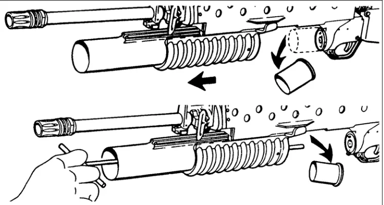
[image:25.612.100.479.321.524.2]To unload the grenade launcher, the grenadier must first depress the barrel latch and move the barrel forward. The cartridge case or round should automatically eject. If the case is stuck, he taps it with a cleaning rod to remove it (Figure 2-2). He places the weapon on SAFE, then slides the barrel rearward, locking it to the breech.
Figure 2-2. Unloading the M203 grenade launcher.
WARNING
2-4. CYCLE OF FUNCTIONING
Knowing the M203’s cycle of functioning from loading to firing helps grenadiers recognize and correct stoppages. Many of the actions described in this chapter occur at once, but here they are explained separately.
a. Unlocking. The cycle begins when the grenadier depresses the barrel latch to unlock the barrel assembly and slides the barrel assembly forward (Figure 2-3).
Figure 2-3. Unlocking the barrel assembly.
b. Cocking. The grenadier moves the barrel assembly forward, then backward, to cock the weapon. As the barrel assembly moves, it takes with it the barrel extension. Their movement causes the following to occur:
(1) The cocking lever is forced down as the barrel assembly and barrel extension, which are interlocked with the cocking lever, move forward.
(2) The movement of the cocking lever forces the spring-loaded firing pin to the rear. (3) The spring-loaded follower also moves forward with the barrel extension.
(4) The barrel assembly continues forward, disengaging the barrel extension from the cocking lever. The cocking lever is then held down by the follower.
(5) When the grenadier begins to move the barrel assembly back to the rear, this forces the follower to the rear.
Figure 2-4. Cocking the M203 grenade launcher.
c. Extracting. Extracting and cocking occur at the same time. As the grenadier opens the barrel assembly, a spring-loaded extractor keeps the live round or spent cartridge case seated against the receiver until the barrel clears the cartridge case (Figure 2-5).
Figure 2-5. Extracting the round or cartridge case.
d. Ejecting. The spring-loaded ejector pushes the live round or spent cartridge case from the barrel assembly (Figure 2-6).
e. Loading. With the barrel assembly open, the grenadier inserts a round into the breech end of the barrel (Figure 2-7).
Figure 2-7. Loading the M203 grenade launcher.
f. Chambering. As the grenadier closes the breech end of the barrel assembly, the extractor contacts the rim of the cartridge and seats (chambers) the round firmly (Figure 2-8).
Figure 2-8. Chambering a round.
g. Locking. As the barrel assembly closes, the barrel latch engages it. The cocking lever engages the barrel extension so that it cannot move forward along the receiver assembly.
CHAPTER 3
DESCRIPTION AND MAINTENANCE
Proper weapon maintenance is a vital part of all gunnery training programs. Good maintenance contributes to weapon effectiveness as well as to unit readiness. This chapter provides a technical description of the M203 grenade launcher, its components, and its ammunition. It also discusses proper procedures for clearing, disassembling, cleaning, lubricating, inspecting, and caring for the weapon.
3-1. DESCRIPTION
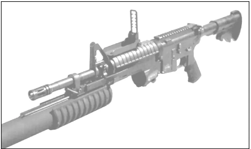
The M203 grenade launcher is a lightweight, single-shot, breech-loaded, pump action (sliding barrel), shoulder-fired weapon that is attached to an M16 rifle series (Figure 3-1), or the M4 carbine series with the M203A1 (Figure 3-2), and M4 carbine series with the rail system (Figure 3-3, page 3-2).
Figure 3-1. M203 grenade launcher (left side view).
Figure 3-3. M4 carbine with rail system.
NOTES: 1. The M203 grenade launcher must be mounted to the M16 rifle series by the unit's armorer, and the M203A1 must be mounted to the M4 carbine rifle series by the unit's supporting DS maintenance company IAW instructions contained in TM 9-1010221-23&P.
3-2. TECHNICAL DATA
The technical data for the M203/M203A1 grenade launcher is as follows: a. Weapon.
Length:
Rifle and grenade launcher (overall) ...99.0 cm (39 inches) Barrel only ...30.5 cm (12 inches) Rifling ...25.4 cm (10 inches) Weight:
Launcher, unloaded...1.4 kg (3.0 pounds) Launcher, loaded...1.6 kg (3.5 pounds) Rifle and grenade launcher, both fully loaded ...5.0 kg (11.0 pounds) Number of lands...6 right hand twist
b. Ammunition.
Caliber...40 mm
Weight...About 227 grams (8 ounces) c. Operational Characteristics.
Action...Single shot Sights:
Front...Leaf sight assembly Rear ...Quadrant sight Chamber pressure...206,325 kilopascals
(35,000 psi) Muzzle velocity...76 mps (250 fps) Maximum range ...About 400 meters
(1,312 feet) Maximum effective range:
Fire-team sized area target ...350 meters (1,148 feet) Vehicle or weapon point target ...150 meters (492 feet) Minimum safe firing range (HE):
Training...130meters(426feet) Combat ...31 meters (102 feet) Minimum arming range ...About 14 to 38 meters
(46 to 125 feet)
Rate of fire ...5 to 7 rounds per minute Minimum combat load ...36 HE rounds
WARNING
3-3. COMPONENTS
Figure 3-4 shows the M203’s major components, and the following paragraphs describe their purposes. The sight assemblies, the trigger and trigger guard, and the safety are shown in Figures 3-5 through 3-10.
a. Handguard. The handguard assembly houses the rifle barrel (Figure 3-4).
Figure 3-4. Components of the M203 grenade launcher.
b. Quadrant Sight Assembly. The quadrant sight assembly, which attaches to the left side of the rifle’s carrying handle, enables the grenadier to adjust for elevation and windage (Figure 3-4). This assembly consists of the sight, mounting screw, sight latch, rear sight aperture, sight aperture arm, front sight post, and sight post arm (Figure 3-5).
Figure 3-5. Quadrant sight assembly.
(1) Clamp, Bracket Assembly, and Mounting Screw. The clamp and the bracket assembly hold the quadrant sight on the rifle’s carrying handle. The mounting screw inserts through the right side of the clamp and into the bracket assembly.
sight post). This procedure allows the sight to pivot on the range quadrant to the desired range setting. The range quadrant is graduated in 25-meter increments from 50 to 400 meters. Applying rearward pressure on the sight latch releases the quadrant sight arm so it can move along the range quadrant. Centering the number in the rear sight aperture selects the desired range. Releasing the sight latch locks the sight in position.
(3) Front Sight Post. The front sight post mounts on the sight post arm by means of a pivot bracket. To prevent damage to the sights, keep the bracket closed when the sights are not in use. Use the sight post as follows to make minor adjustments in elevation when zeroing the launcher:
(a) To decrease elevation, turn the elevation adjustment screw on the sight post clockwise; to increase elevation, turn it counterclockwise.
(b) To move the impact of the projectile 5 meters at a range of 200 meters, turn the elevation adjustment screw one full turn--360 degrees. To move the impact of the projectile 2.5 meters at a range of 200 meters, turn the elevation adjustment screw one half turn--180 degrees.
(4) Rear Sight Aperture. The rear sight aperture is on the sight aperture arm, which is attached to the rear portion of the quadrant sight arm. Use the rear sight aperture as follows to make minor adjustments in deflection (windage) when zeroing the launcher:
(a) To move the impact to the left, press the rear sight aperture retainer down and move the rear sight aperture away from the barrel; to move to the right, move it toward the barrel.
(b) To move the impact of the projectile 1.5 meters at a range of 200 meters, move the rear sight aperture one notch.
c. Receiver Assembly and Serial Number. The receiver assembly houses the firing mechanism and ejection system and supports the barrel assembly. On the left side of the receiver assembly is the launcher’s serial number (Figure 3-4).
d. Barrel Assembly. The barrel assembly holds the cartridges ready for firing and directs the projectile (Figure 3-4).
e. Barrel Latch. On the left side of the barrel is a latch that locks the barrel and receiver together (Figure 3-4). To open the barrel, depress the barrel latch and slide the barrel forward.
Figure 3-6. Leaf sight assembly.
(1) Sight Base. Two mounting screws permanently attach the sight base to the rifle handguard. When the sight is down or not in use, the base protects it from damage.
(2) Sight Mount and Sight. The grenadier uses the sight mount, which is attached to the sight base, to raise or lower the sight. Though the range is not marked on the sight in meters, the sight is graduated in 50-meter increments from 50 to 250 meters, which are marked with a “1” at 100 meters and a “2” at 200 meters.
(3) Elevation Adjustment Screw and Elevation Scale. The screw attaches the sight to its mount. When the screw is loosened, the sight can be moved up or down to make minor adjustments in elevation during the zeroing procedure. The rim of a 40-mm cartridge case is useful for turning the screw. Raising the sight increases the range; lowering the sight decreases the range. The elevation scale consists of five lines spaced equally on the sight. The index line is to the left of the sight. Moving the sight one increment moves the impact of the projectile 10 meters in elevation at a range of 200 meters.
(4) Windage Screw and Windage Scale. The knob on the left end of the windage screw is used to make minor deflection adjustments during the zeroing procedure. The scale has a zero line in its center and two lines spaced equally on each side of the zero line. At a range of 200 meters, turning the knob on the windage scale one increment to the left moves the impact of the projectile 1.5 meters to the right.
DANGER
f. Trigger Guard. The trigger guard protects the trigger (A, Figure 3-6). Depressing the rear portion of the trigger guard rotates it down and away from the magazine well of the rifle, which allows the weapon to be fired while the firer is wearing gloves or mittens (B, Figure 3-7).
Figure 3-7. Trigger guard.
g. Safety. The safety is inside the trigger guard, just in front of the trigger. For the launcher to fire, the safety must be forward. When the safety is rearward, the launcher is on SAFE. The safety is manually adjusted (Figure 3-8).
Figure 3-8. Safety.
3-4. AMMUNITION
WARNING
If fired into snow or mud, 40-mm rounds may not hit hard enough to detonate. An undetonated round may explode when stepped on or driven over. During training in snow or mud, avoid this hazard by firing only TP rounds.
a. Types, Characteristics, and Capabilities. All M203 grenade launcher rounds are fixed rounds (Figure 3-9). (TM 43-0001-28 provides more details.)
Figure 3-9. Cartridges for the M203 grenade launcher.
Figure 3-10. HEDP round.
(2) High-Explosive Round. The HE round has an olive drab aluminum skirt with a steel projectile attached, gold markings, and a yellow ogive (Figure 3-11). It arms between 14 and 27 meters, produces a ground burst that causes casualties within a 130-meter radius, and has a kill radius of 5 meters.
Figure 3-11. HE round.
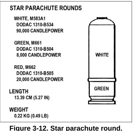
Figure 3-12. Star parachute round.
[image:39.612.174.404.70.296.2](4) White Star Cluster Round. This round is white impact or bar aluminum alloy with black markings (Figure 3-13). The attached plastic ogive has five raised dots for night identification. The round is used for illumination or signals. It is lighter and more accurate than comparable handheld signal rounds. The individual stars burn for about 7 seconds during free fall.
Figure 3-13. White star cluster round.
Figure 3-14. Ground marker round (smoke).
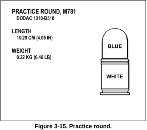
(6) Practice Round. Used for practice, this round is blue zinc or aluminum with white markings (Figure 3-15). It produces a yellow or orange signature on impact, arms between 14 and 27 meters, and has a danger radius of 20 meters.
Figure 3-15. Practice round.
[image:40.612.174.475.390.656.2]in MOUT. It arms between 10 and 30 meters and produces a white cloud of CS gas on impact.
Figure 3-16. CS round.
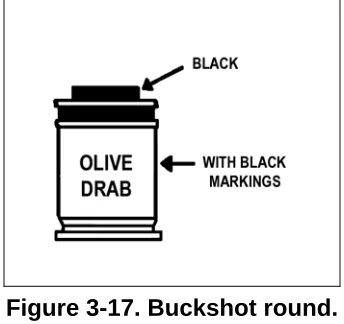
(8) Buckshot Round. This round is olive drab with black markings (Figure 3-17). Though it is a multipurpose round, it is most effective in thick vegetated areas or for room clearing. Inside it has at least 2,000 pellets, which cast a cone of fire 30 meters wide and 30 meters high and travel at 269 meters per second. Be sure to aim buckshot rounds at the foot of the target. The round has no mechanical-type fuse.
Figure 3-17. Buckshot round.
b. Storage. Ammunition should be stored under cover. If this is not possible, store it at least 15 centimeters (6 inches) above the ground and covered with a double layer of tarpaulins. Place the tarpaulins so they protect the ammunition but still allow for ventilation. Dig trenches to prevent water from flowing under the ammunition.
c. Care, Handling, and Preservation. Do not open ammunition containers until you are ready to use the ammunition. Ammunition removed from the airtight container is likely to corrode, particularly in damp climates. Soldiers must take the following precautions:
discovered. Do not fire heavily corroded or dented projectiles or those with loose parts or particles.
(2) Avoid Exposing Ammunition to the Direct Rays of the Sun. Hot powder can cause excessive pressure when the round is fired.
(3) Do Not Lubricate Ammunition. This can cause dust and other abrasives to collect on it and damage the operating parts of the launcher.
d. Packaging. Ammunition packaging varies according to the type of ammunition: (1) HE, HEDP, and TP. Each box of HE, HEDP, and TP ammunition contains 1 can with 6 bandoleers of 12 rounds each, for a total of 72 rounds.
(2) Smoke and Cluster Ammunition. Each wire-bound box of smoke and cluster ammunition contains 2 cans with 22 rounds each, for a total of 44 rounds.
(3) CS Ammunition. Each box of CS ammunition contains 2 cans with 4 bandoleers of 6 rounds each, for a total of 48 rounds.
(4) Buckshot. Each box of buckshot ammunition contains 12 bandoleers of 6 rounds each, for a total of 72 rounds.
3-5. CLEARING PROCEDURES
The soldier must clear the weapon before performing maintenance on it. FM 23-9 (3.22.9) provides instructions for clearing an M16-series rifle. To clear the grenade launcher--
a. Push in the release button and pull the barrel forward. b. Watch to see if a round extracts.
c. Place the safety on SAFE.
d. Inspect the breech to ensure a round is not present.
e. Pull the barrel to the rear until it clicks. This cocks the weapon. f. Place the safety on FIRE.
3-6. GENERAL DISASSEMBLY
When disassembling the weapon, the soldier places each part, as it is removed, on a clean, flat surface such as a table, shelter half, or disassembly mat. This aids in reassembly and simplifies the task of keeping up with the parts. The soldier will later assemble the grenade launcher in the reverse order that he disassembled it (paragraph 3-9). (Only ordnance personnel disassemble the grenade launcher beyond the steps described here.) To disassemble the weapon--
Figure 3-18. Removing the quadrant sight assembly.
b. Remove the barrel assembly and handguard assembly, in either order:
(1) Barrel Assembly First. Push the barrel latch and move the barrel forward until it hits the barrel stop. On the left side of the handguard, insert a cleaning rod into the fourth hole back from the muzzle, depress the barrel stop, and slide the barrel forward and off (Figure 3-19).
Figure 3-19. Removing the barrel assembly before the handguard assembly.
Figure 3-20. Removing the handguard assembly before the barrel assembly.
3-7. CLEANING AND LUBRICATION
After firing the grenade launcher, or if it has been idle for a long time, the soldier must clean and lubricate it as follows:
a. Bore. Attach a clean, dry rag to the thong and thoroughly moisten the rag with CLP. Pull the rag through the bore several times. Attach the bore brush to the thong, pull it through the bore several times, and follow this with more rags moistened with CLP (Figure 3-21). Pull dry rags through the bore, and inspect each rag as it is removed. The bore is clean when a dry rag comes out clean. Finally, pull a rag lightly moistened with CLP through the bore to leave a light coat of lubricant inside the barrel.
Figure 3-21. Cleaning the barrel with thong and bore brush.
b. Breech Insert. Clean the face of the breech insert with a patch and CLP. Remove this CLP with dry rags; then lubricate the breech with a new, light coat of CLP.
c. Other Parts. Use a brush and dry rags to clean all the other parts and surfaces. After cleaning, apply a light coat of CLP to the outside of the launcher.
d. Safety Mechanism. Clean the safety mechanism properly with CLP; then
lubricate it with CLP.
e. Special Lubrication Requirements. Lubricate the grenade launcher only with CLP and IAW the following environmental guidelines:
(2) Damp or Salty Air. Clean the weapon and apply CLP, grade 2, frequently.
(3) Sandy or Dusty Air. Clean the weapon and apply CLP, grade 2, frequently. Remove excess CLP with a rag after each application.
(4) Temperatures Below Freezing. When the weapon is brought in from a cold area to a warm area, keep it wrapped in a parka or blanket, and allow it to reach room temperature gradually. If condensation forms on the weapon, dry and lubricate it at room temperature with CLP, grade 2, before returning it to cold weather. Otherwise, ice will form inside the mechanism.
NOTE: Although CLP provides the required lubrication at temperatures down to
-35°F (-37°C), it will not flow from a 1/2-ounce bottle at temperatures below 0°F (-17°C).
3-8. INSPECTION
Inspection begins with the weapon already disassembled into its major groups or assemblies. Parts with shiny surfaces are serviceable. The following parts of the weapon and related equipment are inspected IAW TM 9-1010-221-10:
a. All Parts. Check for wear and damage, including burrs, scratches, and nicks. b. Handguard. Check for cracks, dents, or distortion that prevents its firm attachment to the rifle.
c. Leaf Sight Assembly. Check for bent or damaged parts, rust or corrosion, and illegibility of markings.
d. Barrel. Check for cracks or dents.
e. Cartridge and Retainers. Check for breakage, bends, chips, or missing parts.
NOTE: Take any unserviceable part to the armorer, who will determine its
serviceability and replace parts as necessary.
3-9. GENERAL ASSEMBLY
The soldier assembles the grenade launcher in the reverse order of disassembly.
a. Install the barrel by pressing the barrel stop and sliding the barrel into the receiver (Figure 3-22).
b. Lock the barrel by moving it rearward until it closes with a click (Figure 3-23).
Figure 3-23. Locking the barrel.
c. Install the handguard and secure it with the slip ring (Figure 3-24).
Figure 3-24. Installing and securing the handguard.
Figure 3-25. Installing the quadrant sight assembly.
e. Perform a function check to ensure that the grenade launcher has been assembled correctly. Notify the unit armorer at once if the launcher fails to function. Conduct the function check in this order:
(1) Check the proper operation of the sear. Cock the launcher and pull the trigger. The firing pin should release with a metallic click. Hold the trigger to the rear and cock the launcher again. Release the trigger, then pull. The firing pin should again release.
WARNING
If the sear malfunctions, the launcher could fire without the trigger being pulled.
(2) Check the safety by pulling the trigger in both the SAFE and FIRE positions. The launcher must be cocked before the safety can be placed in the SAFE position.
(3) Check the leaf sight assembly windage adjustment screw for proper operation. Move the elevation adjustment screw only if the weapon has been zeroed.
(4) Move the barrel forward and back to be sure the barrel stop and barrel latch function.
3-10. CARE AND HANDLING
Certain steps must be taken before, during, and after firing to properly maintain the grenade launcher.
a. Before firing.
• Wipe the bore dry.
• Inspect the weapon as outlined in the operator’s technical manual.
• Ensure the weapon is properly lubricated. b. During firing.
• When malfunctions or stoppages occur, follow the procedures outlined in Chapter 4.
3-11. CARE AND HANDLING UNDER NBC CONDITIONS
If contamination is anticipated, the soldier should apply CLP to all outer metal surfaces of the weapon. Ammunition, however, should never be lubricated. The soldier should keep the weapon covered as much as possible. If the weapon is contaminated, he should decontaminate it IAW FM 3-3 and FM 3-4 and then clean and lubricate it.
3-12. DECONTAMINATION
Leaders must try to reduce the penetration of contaminants and exposure to them. Contaminated material is disposed of IAW SOP.
a. Nuclear. Wipe off the weapon with warm soapy water. Otherwise, use towelettes or rags. (FM 3-5 provides details.)
b. Biological. Use towelettes from the M258A1 kit to wipe off the weapon. If these are not available, wash with soap and water.
CHAPTER 4
PERFORMANCE PROBLEMS AND DESTRUCTION
This chapter identifies some of the problems that can cause the M203 grenade launcher to perform incorrectly. It also explains how to identify unserviceable parts and how to destroy the weapon when authorized to do so.
4-1. MALFUNCTIONS
A malfunction occurs when a mechanical failure prevents the weapon from firing properly. Neither defective ammunition nor improper operation of the weapon by the firer is a malfunction. The weapon should be cleaned, lubricated, and retried. If it still fails to function, it should be turned in to the unit armorer. Table 4-1 shows probable causes and corrective action for each type of malfunction.
Malfunction Probable Cause Corrective Action
Broken sear
Improper assembly of cocking lever Failure to cock
Loose, broken, or missing cocking lever spring pin
Failure to lock Excess plastic on breech end of
barrel assembly
Notify unit maintenance
Table 4-1. Malfunctions.
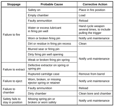
4-2. STOPPAGES
Stoppage Probable Cause Corrective Action
Safety on Place in fire position
Empty chamber Load
Faulty ammunition Reload
Water or excess lubricant in firing pin well
Hand cycle weapon several times, to include pulling the trigger
Worn or broken firing pin Notify unit maintenance
Dirt or residue in firing pin recess Clean
Blurred sear or firing pin
Dirty firing pin well opening Failure to fire
Weak or broken firing pin spring
Defective extractor on spring or spring pin
Notify unit maintenance
Failure to extract
Ruptured cartridge case Remove from barrel
Failure to eject Worn, broken, or missing
ejector spring or retainer Notify unit maintenance
Faulty ammunition Reload
Failure to
chamber Dirty chamber Clean bore and chamber
Safety fails to stay in position
Missing spring pin or
[image:50.612.94.485.68.428.2]broken or worn safety Notify unit maintenance
Table 4-2. Stoppages.
4-3. IMMEDIATE ACTION
Immediate action refers to anything a soldier does to reduce a stoppage without taking time to look for the cause. Immediate action should be taken in the event of either a hangfire or misfire. Either can be caused by an ammunition defect or by a faulty firing mechanism. Any failure to fire must be considered a hangfire until that possibility is eliminated.
• A hangfire is a delay in the functioning of the round’s propelling charge explosive train at the time of firing. The length of this delay is unpredictable, but in most cases, it ranges between a split second and 30 seconds. Such a delay in the functioning of the round could result from the presence of excess oil or grease, grit, sand, frost, or ice.
• A misfire is a complete failure of the weapon to fire. A misfire in itself is not dangerous, but because it cannot be immediately distinguished from a hangfire, it must be considered to be a hangfire until proven otherwise.
a. Keep the M203 pointed downrange or at the target and keep everyone clear of its muzzle. If the stoppage occurs during training, shout MISFIRE and clear the area of any soldiers not needed for the operation.
b. Wait 30 seconds from the time of the failure before opening the barrel assembly to perform the unloading procedure.
c. After removing the round from the receiver, determine whether the round or the firing mechanism is defective. Examine the primer to see if it is dented. If the primer is dented, separate the round from other ammunition until it can be disposed of properly. However, if the primer is not dented, the firing mechanism is at fault. Once the cause of the failure to fire has been corrected, the round may be reloaded and fired.
WARNING
If you are unloading a weapon that has not been fired, avoid detonation either by catching the ejected round or by holding the weapon close to the ground to reduce the distance the round can fall.
4-4. REMEDIAL ACTION
Remedial action is any action taken by the gunner to restore his weapon to operational condition. Take remedial action only if immediate action does not remedy the problem.
4-5. DESTRUCTION PROCEDURES
Destruction of any military weapon is authorized only as a last resort to prevent the enemy from capturing or using it. This paragraph discusses planning for destruction, priorities and methods of destruction, and degree of damage. In combat situations, the commander has the authority to destroy weapons, but he must report doing so through channels.
a. Planning. SOPs for all units should contain a plan for destroying equipment. Having such a plan ensures that the damage is effective enough to deny use of the equipment to the enemy. The plan must be flexible enough in its designation of time, equipment, and personnel to meet any situation.
b. Priorities of Destruction. When lack of time prevents them from completely destroying equipment, soldiers must destroy the same essential parts on all like equipment. The order in which the parts should be destroyed (priority of destruction) is as follows:
(1) Bolt assembly (M16) and breech mechanism (M203). (2) Barrels (both M16 and M203).
(3) Sights or sighting equipment (including nightsight). (4) Optics mount.
c. Methods of Destruction. Equipment may be destroyed by any of several
(1) Mechanical. Use an axe, pick, sledgehammer, crowbar, or other heavy implement.
(2) Burning. Use gasoline, oil, incendiary grenades, other flammables, or a welding or cutting torch.
(3) Demolition. Use suitable explosives or ammunition or, as a last resort, hand grenades.
(4) Disposal. Bury essential parts, dump them in streams, or scatter them so widely that recovering them would be impossible.
CHAPTER 5
MARKSMANSHIP TRAINING
Marksmanship training is conducted in three phases. This chapter discusses the first two phases: preliminary marksmanship training, which develops nonfiring individual skill proficiency (Section I), and basic gunnery, during which the soldier learns to apply the fundamentals of gunnery and to zero the M203 during qualification exercises in day, NBC, and night conditions (Section II). Chapter 6 discusses the third phase, advanced gunnery. Every phase has the same three objectives: to teach each grenadier to hit the target accurately with the first round, to adjust fire, and to do both quickly.
WARNING
Before allowing anyone to move between stations, ensure that all rifles and grenade launchers have been cleared, that bolts are to the rear, and that barrel assemblies are in the open position. Anyone observing an unsafe act should call CEASE FIRE and notify range personnel immediately.
Section I. PRELIMINARY MARKSMANSHIP TRAINING
Grenadiers and leaders must master marksmanship fundamentals before firing individually or collectively. During preliminary marksmanship training, grenadiers learn and demonstrate the individual skills that prepare them to fire live ammunition. After learning the characteristics and mechanics of the weapon (Chapters 2, 3, and 4), they learn the four fundamentals of marksmanship, sight manipulation, and response to fire commands. Dry-fire exercises are excellent for training to proficiency. Good preliminary marksmanship instruction improves individual proficiency, which in turn improves the proficiency of collective fire.
5-1. FOUR FUNDAMENTALS OF MARKSMANSHIP
The four fundamentals of M203 marksmanship are steady position, aiming, breathing, and trigger control. Only the first fundamental (steady position) varies. The other three remain the same regardless of the soldier’s position.
a. Steady Position. This varies according to the position and the type of sight used (quadrant or leaf).
(1) Prone Position. When firing prone, a supported position is best. (a) Quadrant Sight (Figure 5-1, page 5-2).
• Lie face down, grasp the M16 pistol magazine with your right hand, and place the butt of the rifle into the pocket of your right shoulder.
• Grasp the barrel grip with your left hand, supporting with sandbags. Straighten your upper body and spread your legs a comfortable distance apart. Try to point your toes outward and relax your ankles so your heels will rest on the ground. Relax the weight of your upper body forward onto your left arm.
Figure 5-1. Prone supported position, quadrant sight.
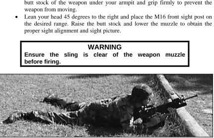
(a) Leaf Sight (Figure 5-2).
• While firing with the leaf sight at ranges greater than 150 meters, place the butt stock of the weapon under your armpit and grip firmly to prevent the weapon from moving.
• Lean your head 45 degrees to the right and place the M16 front sight post on the desired range. Raise the butt stock and lower the muzzle to obtain the proper sight alignment and sight picture.
WARNING
Ensure the sling is clear of the weapon muzzle before firing.
(2) Kneeling Position.
(a) Quadrant Sight (Figure 5-3).
• Kneel on your right knee while facing the target with your right hand on the magazine and your left hand grasping the barrel grip.
• Place your left foot about .45 meter (18 inches) to your left front with your toes pointing in the general direction of the target.
• Keeping your right toe in place, sit on your right heel.
• Place your left elbow forward of your left knee, resting the flat portion of your upper arm on your knee.
• Move the rifle butt into the pocket of your right shoulder, pulling the rifle magazine with your right hand and grasping the barrel grip with your left hand.
• With your right hand on the rifle magazine, place your right forefinger in the trigger guard of the grenade launcher.
• Pull the rifle firmly into your shoulder.
[image:55.612.187.462.343.663.2]• Pull your right elbow in close to your body to help you apply rearward pressure to the weapon. Ensure that your leg completes a solid, three-point base for your position.
Figure 5-3. Kneeling position, quadrant sight.
• For ranges greater than 150 meters, place the butt stock of the weapon under your armpit and grip firmly to prevent the weapon from moving.
[image:56.612.150.426.156.486.2]• Lean your head 45 degrees to the right and place the front sight post of the M16 on the desired range. Raise the butt stock and lower the muzzle to obtain the proper sight alignment and sight picture.
Figure 5-4. Kneeling position, leaf sight.
(3) Sitting Position, Open-Legged. (a) Quadrant Sight (Figure 5-5).
• Sit down, breaking your fall with your right hand, and slide your buttocks well to the rear. Face the target half right, and spread your feet wide.
• Grasp the rifle magazine with your right hand and the barrel grip with your left hand.
• Bend forward from your hips.
• Pull the weapon down slightly with your left hand and pull it to the rear firmly with your right hand.
Figure 5-5. Sitting position, open-legged, quadrant sight.
(b) Leaf Sight (Figure 5-6, page 5-6).
• Lean your head 45 degrees to the right and place the M16 front sight post on the desired range. Raise the butt and lower the muzzle to obtain the proper sight alignment and sight picture.
Figure 5-6. Sitting position, open-legged, leaf sight.
(4) Sitting Position, Cross-Ankle. (a) Quadrant Sight (Figure 5-7).
• Sit facing the target half right.
• Extend your legs from your body and cross your left ankle over your right ankle.
• Keep both ankles straight.
• Place your left upper arm across your left knee.
[image:59.612.115.533.85.474.2]• Move the butt of the rifle into the pocket of your right shoulder.
(b) Leaf Sight (Figure 5-8).
• For ranges greater than 150 meters, place the butt stock of the weapon under your armpit and grip firmly to prevent the weapon from moving.
[image:60.612.88.492.168.525.2]• Lean your head 45 degrees to the right and place the M16 front sight post on the desired range. Raise the butt and lower the muzzle to obtain the proper sight alignment and sight picture.
(5) Sitting Position, Cross-Legged. (a) Quadrant Sight (Figure 5-9).
• Sit down facing the target half right.
• Cross your left leg over your right leg and draw both feet close to your body.
• Grasp the rifle magazine with your right hand.
[image:61.612.119.532.182.598.2]• Move the butt of the rifle into the pocket of your right shoulder, and grasp the rifle barrel grip properly with your left hand.
(b) Leaf Sight (Figure 5-10).
• For ranges greater than 150 meters, place the butt stock of the weapon under your armpit and grip firmly to prevent the weapon from moving.
[image:62.612.78.498.171.530.2]• Lean your head 45 degrees to the right and place the M16 front sight post on the desired range. Raise the butt and lower the muzzle to obtain the proper sight alignment and sight picture.
(6) Squatting Position.
(a) Quadrant Sight (Figure 5-11).
• Turn half right to the target and, keeping both feet flat on the ground and a comfortable distance apart, squat as low as you can.
• Grasp the rifle magazine with your right hand.
• Place your left upper arm inside your left knee and the butt of the rifle into the pocket of your right shoulder. Grasp the rifle barrel grip properly.
[image:63.612.124.528.184.557.2]• Lower your right elbow against the inside of your right knee.
(b) Leaf Sight (Figure 5-12).
• For ranges greater than 150 meters, place the butt stock of the weapon under your armpit and grip firmly to prevent the weapon from moving.
[image:64.612.100.477.167.623.2]• Lean your head 45 degrees to the right and place the M16 front sight post on the desired range. Raise the butt and lower the muzzle to obtain proper sight alignment and sight picture.
Figure 5-12. Squatting position, leaf sight.
(7) Fighting Position.
(a) Quadrant Sight. If possible, use support when firing from a fighting position (Figure 5-13).
• Grasp the magazine with your right hand.
• Place your left elbow on or against solid support.
• Use your right hand to position the butt of the rifle in the pocket of your right shoulder. Grasp the rifle barrel grip properly.
• Place your right elbow on or against a solid support and relax into a comfortable firing position.
[image:65.612.118.532.191.516.2]NOTE: The weapon must not touch the support.
(b) Leaf Sight (Figure 5-14).
• For ranges greater than 150 meters, place the butt stock of the weapon under your armpit and grip firmly to prevent the weapon from moving.
[image:66.612.74.506.169.533.2]• Lean your head 45 degrees to the right and place the M16 front sight post on the desired range. Raise the butt and lower the muzzle to obtain proper sight alignment and sight picture.
Figure 5-14. Fighting position, leaf sight.
(8) Standing Position.
(a) Quadrant Sight (Figure 5-15).
• Face the target while standing with your feet spread a comfortable distance apart.
• Grasp the rifle barrel grip with your left hand and the rifle magazine with your right hand.
• Place the butt of the stock into your right shoulder so that the sight is level with your eyes.
• Hold your right elbow high to form a good pocket for the butt of the stock and to permit a strong rearward pressure with your right hand.
• Shift your feet until you achieve a natural aiming stance.
(a) Leaf Sight (Figure 5-16).
• For ranges greater than 150 meters, place the butt stock of the weapon under your armpit and grip firmly to prevent the weapon from moving.
[image:68.612.119.458.168.662.2]• Lean your head 45 degrees to the right and place the M16 front sight post on the desired range. Raise the butt and lower the muzzle to obtain the proper sight alignment and sight picture.
b. Aiming. Aiming procedures for every position are as follows:
[image:69.612.106.545.183.400.2](1) Aligning Sight. When using the leaf sight, align it with the front sight post of the M16. When using the quadrant sight, align its rear sight aperture with its front sight post. Picture a horizontal line through the center of the leaf sight or rear sight aperture: the top of the M16’s front sight post should touch this line. Picture a vertical line through the center of the leaf sight or rear sight aperture: this line should vertically bisect the front sight post (Figure 5-17).
Figure 5-17. Sight pictures for leaf and quadrant sights.
(2) Focusing. For either sight, focus on the front sight post. A good firing position places your eye directly on line with the center of the leaf sight or rear sight aperture. Your eye’s natural ability to center objects in a circle and seek the point of greatest light will help you align the sight correctly.
(3) Obtaining Sight Picture. To achieve a correct sight picture, align the front sight post and the leaf sight or rear sight aperture with the target. For area targets, aim where the round’s bursting radius will make the round most effective. For point targets, aim at the target’s center of mass.
c. Breathing. The technique for breathing is the same for every position: Breathe naturally, exhale most of your air, hold your breath, and fire before you become uncomfortable. In combat, just choke off your breath before firing.
d. Trigger Control. The technique for trigger control is the same for every position. Place your trigger finger (the index finger of your right hand) so that the trigger is between the first joint and the tip of your finger (not at the extreme end of your finger). Adjust for your hand size and grip. Then, squeeze your trigger finger to the rear without disturbing the lay of the weapon.
5-2. LIMITED VISIBILITY
a. Steady Position. An M203 with an AN/PVS-4 mounted on it leans to the left. When assuming a steady position, the grenadier must apply more rearward pressure to compensate for the lean and then steady the weapon.
b. Aiming. The grenadier sights with the reticle of the AN/PVS-4 rather than with the M203’s iron sights. Sighting this way requires him to change position, which breaks his stock weld and makes the weapon seem heavier.
c. Breathing. Though breathing itself is affected little by limited visibility, using night vision devices that magnify the field of view increases the effect of weapon movement caused by breathing.
d. Trigger Control. This is the same regardless of visibility conditions. The objective is to keep the weapon aligned with the target.
e. Night Vision Devices. The AN/PVS-7 is issued for use with the M203, whereas the AN/PVS-4 is normally issued for use with crew-served weapons. M203 gunners may qualify with either device. In a defensive position, the gunner identifies targets during daylight and constructs aiming or elevation stakes. Because the AN/PVS-7 rear sight must be set to the far setting to sense rounds, the gunner cannot see both the M203 sights and the target at the same time. Therefore, stakes are more important with the AN/PVS-7 than with the AN/PVS-4. (On the rear sight of the M16A1, the far setting is “L.” On the rear sight of the M16A2, the far setting is “02.”)
f. Marked-Sling Method. The best field-expedient method for firing the M203 grenade launcher in limited visibility is the marked-sling method using only the M16 rifle series (Figure 5-18). To use this method, the grenadier must--
(1) Face the target and kneel on the right knee (if firing right-handed), keeping the left foot pointed toward the target.
(2) Loosen the sling and place the forward foot in the sling. (3) Place the butt of the stock firmly on the ground.
Figure 5-18. Marked-sling method.
WARNING
Placing the knee against the buttstock can cause injury.
(6) Ensure the sling is taut and vertical between the front sling swivel and the boot (Figure 5-19). If not, the rounds will impact at a greater range than desired.
Figure 5-19. Front-sling swivel and front of boot.
(8) Mark the sling (where it is held to the ground by the foot) with colored tape, paint, ink, or whatever is available. Mark the position of the buckles (Figure 5-20) so that, if either is moved, the grenadier can return them to their original positions and be assured of constant range accuracy.
Figure 5-20. Marked sling and buckle highlighted.
(9) If the sling gets wet, it may stretch or shrink, indirectly causing the rounds to impact closer or farther than desired.
5-3. NBC ENVIRONMENT
The fundamentals of marksmanship remain valid in the NBC environment, but some modifications may be needed to accommodate the equipment.
a. Steady Position. Bulky NBC wear requires the grenadier to press the stock of the weapon more firmly into his shoulder pocket.
b. Aiming. Aiming is affected little by NBC.
c. Breathing. Wearing the protective mask makes breathing more difficult.
Grenadiers must try to breathe normally to avoid hyperventilating while firing. d. Trigger Control. All soldiers must wear rubber gloves.
5-4. FIRE COMMANDS
Standard fire commands are explained to grenadiers and are used during all subsequent gunnery training. Trainers give the appropriate elements before each dry-fire or live-fire exercise. The grenadier performs as directed and repeats each element as it is announced. (Chapter 6 provides a detailed explanation of fire commands.)
a. Alert. The trainer gives the alert as a fire mission. On hearing this, the grenadier loads the weapon and moves the safety lever to FIRE.