Conference on
AppliedA1ononCo~ol1987
A UNIVERSAL INTELLIGENT MICRO-CONTROLLER-BASED SPINDLE DRIVE SYSTEM FOR HARD DISK DRIVES
Fred Kurzweil, Jr. MAXTOR Corporation
San Jose, California
Abstract: This paper, which addresses the design aspects of intelligent and robust Spindle control for small hard disk drives, is divided into three parts:
1.) An Overview of the design of the Spindle Drive Control System considering the multi-functional requirements of a Spindle System in a computer environment;
2.) Hardware design of the Spindle control including an embedded Il-Controller with interfaces to digital and analog hardware; and
3.) Algorithm design for the Il-Controller to provide the Spindle control and Spindle auxiliary functions.
Features of the Spindle control system include:
*0.1 % precision Spindle speed control at 3596 RPM .. *Il-Controller capability to allow local Spindle
control calibration and adaptation of the Spindle control system to various Drive families.
*Optimized Electronic Commutation to minimize electrical and acoustical noise.
*In-Line diagnostic capability.
*Multi-Spindle synchronization capability.
1. Introduction
The role of Spindle Drives in Low-End High Capacity Winchester Disk Drives has gravitated from one of relatively modest performance demands on the Spindle control system to one with sophisticated functional capability in addition to tightened performance requirements. This demand stems from the same factors which traditionally have pushed magnetic disk drive technology toward higher storage, faster accessing and reacl/write performance, all at lower (competitive) cost per Megabyte of storage.
The intent of this paper is to demonstrate a cost-effective engineering solution to Spindle Drive control requirements in the small Disk Drive environment by taking advantage of the speed, intelligence, and cost characteristics of a Zilog Z8 Il-Controller embedded in the hardware and thereby providing logical control of a multiplicity of tasks.
Fred Kurzweil, Jr. PhD MAXTOR Corporation
211 River Oaks Pkwy, San Jose, CA 95134 Tel. (408)-432-1700 Ext 4533
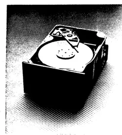
The MAXTOR XT-8000ETM Drive shown in Figure 1 is used as the vehicle to illustrate the interaction implicitly between the electronic hardware design, the Il-Controller algorithms, and Spindle control implementation.
The XT-8000 Drive is a state-of-the-art 5.25 inch drive with 760 Megabyte Capacity and accessing performance of less than 20 milliseconds for which the Spindle control system described in this paper was developed; the synergistic relationship of control system synthesis with a Il-Controller and the associated hardware/firmware development will become apparent in the following presentation, especially with respect to the intelligent capability of the Il-Controller.
2. Overview
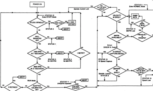
[image:1.627.300.551.382.660.2]The flowchart of Figure 2 is used as the basis to illustrate the functionality of the Spinc!le control system; Fi.gure 2
Figure 1. MAXTOR XT-8000ETM
760MB, 5.25-inch Winchester Disk Drive (Photo Courtesy of MAXTOR Corporation)
This paper presented at: University of Minnesota
Conference on Applied Motion Control '87 June 16-18. 1987
Corijerence on
AflpliedMotion Control 1987
is a diagramatic description of the In-Line/Real-Time Il-Controller Diagnostics for the Spindle control system.
The flowchart describes the sequence of Il-Controller activity required during each of the Spindle Modes of operation; this sequence provides a detailed Overview of the diverse control and auxiliary functions of the Spindle. The sequence, programmed as algorithms in the Il-Controller, provides three basic modes of operation for the Drive: a START Mode, a RUN Mode, and a SYNSPIN Mode.
START Mode: At power-up, with the Spindle at rest, full current (limited to 4 Amperes) is applied to the Spindle motor. Progressive diagnostic and timing checks are performed to detect a Spindle Drive malfunction and to take corrective action as follows:
a.) Detect a stalled Spindle Motor:
The Hall Sensors are tested for (commutation) motion. If 1 second elapses without motion, either a ·stuck· Spindle or a Power Module failure is indicated; Actuator Dither is invoked to free up the Spindle. At the end of 1 second of Dither, motion is checked again and if not detected, STATUS 2 is
posted and the Spindle ABORTS (powers down).
b.) Detect a Hall Sensor Failure:
The states of the Hall Sensors are continuously checked at commutation. If an illegal state occurs in two consecutive revolutions, STATUS 1 is posted and the Spindle ABORTS.
c.) Check 1000 RPM @ 7 seconds:
The commutation is timed for 1000 RPM to occur within 7 seconds. If 1000 RPM does not occur, this indicates excessive drag forces from the heads or bearings, or a motor/driver failure; STATUS 3 is posted and the Spindle ABORTS.
d.) Check 3600 RPM @ 21 seconds:
The commutation is timed for 3600 RPM to occur within 21 seconds. If 3600 RPM is not achieved within 21 seconds, STATUS 4 is posted and the system goes into one START RETRY before an ABORT; in contrast to a.) and c.), a sufficient back emf from the motor has reduced the voltage overhead across the drivers in the Power Module such that the reduced power dissipation of the drivers allows multiple retries. (RETRY is performed beyond this point for any return into the START Mode.)
RUN MOPE: Upon entering RUN Mode, the J.I.-Controller sequentially enters a.) an Adaptive routine to compute the quiescent Drag force of the bearings/disks and to compute the dynamic system constant from DAC input to motor velocity, b.) an electronic commutation routine which provides make-before-break commutation, c.) a velocity lock-on routine (in 30 revolutions) to insure (monitored) velocity operation of 3596 RPM
±
0.1 %. The system is then given a STATUS 0 identification of Normal Mode operation. If a failure occurs at any point between a.) to c.), the system goes into a RETRY Mode (into the START Mode) and is monitored for 5 successive failures without velocity lock-on before ABORT. [image:2.620.28.552.400.712.2]STAlUSO Enter NORMAl Mode
Figure 2. Spindle FunctionaVDiagnostic Flow Chart
At velocity lock-on, a READY signal is posted to the interface fJ.-Controiler to signal that the Spindle is at recording velocity, i.e., 3596 RPM ± 0.1 %.
A feature of the XT-8000 Drive family is the capability of synchronous spindle operation (Spindle Locked operation) in which INDEX lock is achieved between a Master Drive and N Slave Drives, where N can be up to 48 Drives. This feature allows serial data streams to operate in parallel and thereby effectively multiplies the system data transfer rate (Drive-to-Host Computer) by N.
The implications of this feature on Drive System Performance vs Total System Capacity are manifest and will lead to many innovative applications of the feature at the system level; the feature allows the user the flexibility to tailor his Drive Subsystem to the Capacity/Channel Rate requirements of the Host System.
With the drive in the RUN Mode, the code of the fJ.-Controller provides two simultaneous functions: 1.) Generation of a Master Pulse Out (MAPOUT), and 2.) Search for a Master Pulse In (MAPIN). Normal Mode operation implies the lack of a MAPIN pulse and while in this Mode, the Drive defaults to a Master Drive designation.
If a MAPIN Pulse is detected, the Drive is posted with a Slave Drive deSignation (MAPIN available) and the following sequence takes place:
e.) Upon detection of MAPIN by the wController, the Slave Drive enters a high-speed CAPTURE Mode to bring the MAPIN Pulse to the MAP Window. Normal velocity control is in effect during this operation (NORMAL Mode).
f.) As MAPIN approaches the outer boundaries of the MAP Window, a velocity adjustment is made to the Slave Drive to return the drive to Normal velocity prior to entering the MAP Window and subsequent phase lock. Within the MAP Window, bounds are tested for velocity error and phase error (MAPERR). When the two are within their tolerance zones, the system switches to a phase controlled configuration wherein the SLAVE Drive is locked to the MAPIN Pulse and Synchronous Spindle operation (Spindle Locked) STATUS 8 is posted.
g.) In the SYNCSPIN Mode, the velocity and phase error are constantly monitored to assure velocity and INDEX phase tolerances as follows:
Velocity: 3596 RPM
±
0.1 %Master INDEx/Slave INDEX Lock: ±20 fJ.seconds
If the SYNCSPIN Lock error (MAPERR) is out of tolerance (STATUS 10), the system reverts to the CAPTURE Mode; if the velocity is out of tolerance (Spindle Control lost), up to 5 consecutive RETRIES are performed via the START Mode (recalibration of the Adaptive Loop) and if SYNCSPIN is not achieved (with MAPIN available), a SYNCSPIN Inoperative condition (STATUS 11) error is posted and the
Conference on
Applied Motion Control 1987
system attempts operation in the Normal Mode.
In the following sections, additional detail is provided on the hardware and software implementation of the above sequence.
The major attribute of the control design involves an architecture of the control system which provides robust control over all of the multi-functional requirements implied above. As will be shown, this is achieved by the use of a Simple first-order velocity control loop in which the long-term steady state velocity error (due to external variable drag/bearing forces) is nulled out by a compensating torque current adaptively generated by the I-L-controller and which tracks the velocity error. Robustness of the control is achieved by the ability of the first-order velocity control loop to operate over a wide range of parameter tolerances and its ability to recover after exceeding the tolerances or after having lost control.
The combination of a simple control system driven by the intelligence capabilities of the fJ.-Controller allows a partitioning of diverse complex functions, as above, into simple tasks, thus playing directly to the technical strength of the fJ.-Controller, Le., breaking a complex task into a sequence of simple tasks (algorithms).
3. Spindle Control System Hardware
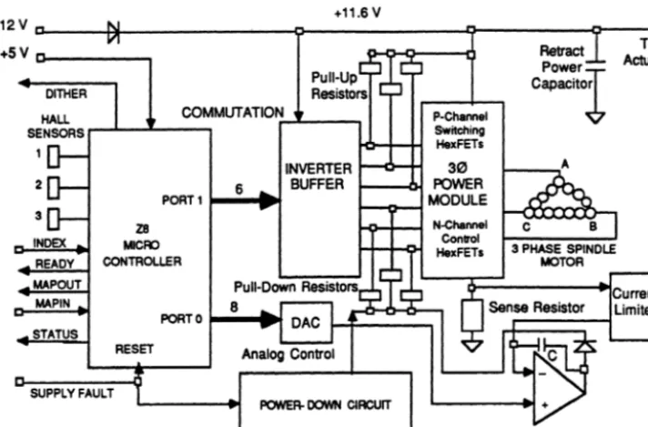
'Figure 3. presents a component block diagram of the Spindle Control System which provides the functions described above in the Overview. The Z8 fJ.-Controller is the central element in this diagram, serving to coordinate, direct, and control all of the activity of the spindle.
The output of the Hall Sensors is mapped by the Z8 into a 30 commutation sequence which continuously commutates the in-the-hub 4 pole 30 spindle drive motor through the 30 H-Bridge Power Module (6 Power Transistors). The current through the motor is monitored by the voltage across the 0.1
n
Sense Resistor. Current control is obtained by comparing the sense voltage with the DAC output at a high gain op-amp and then closing the analog control loop through the (lower) power transistors; an integrating capacitor around the op-amp stabilizes the loop. The net effect of this loop is to provide calibrated current through the motor and to desensitize the circuit to variations in the power transistor parameters.Additional analog circuitry shown in Figure 3 provides current limiting of the motor current (to the 4 Amp industry standard) and provides graceful shut-down (homing of the actuator and dynamic braking of the spindle) in the event of loss of power (Le., loss of the fJ.-Controller).
The design philosophy for this circuit accentuates the utilitarian role of the fJ.-Controller and in fact takes advantage of the intelligence of the fJ.-Controller in several unusual directions:
Conference on
Applied Motion Control 1987
+11.6 V
+12VC-____
~---~~---~---~~--~
To+5 V 0---., Retract Actuator
Power
DITHER
Pull-Up Resistors
HALL COMMUTATION~~_ ....
SENSORS ..-..L..--lI:"'-_ _ ....,
P-Chamel Switching HexFETs
Capacitor
2 6
INVERTER 1--0-+1
BUFFER
30 POWER
1---0--1 MODULE
3
INDEX
READY MAPOUT
MAPIN
STATUS
PORT 1
1---_
Z8
MCFD
CONTROLLER
Pull-Down Resistors
8 PORTO
1--_
RESET Analog Control
SUPPLY FAULT
J-a..-I--I N-Channel ConlrOl
HexFETI 3 PHASE SPINDLE
MOTOR
POWER-OOWN CIRCUIT
[image:4.627.112.468.50.284.2]OpAmp
Figure 3. Spindle p-ControllerlElectronic Control Hardware
*A partitioning
'01
power components from signal components to allow engineering, tailoring, and packaging of components into various space and power formats.*A standard interlace has been provided for the Power Module allowing tailoring/cost advantages.
*Hardware "hooks" have been provided in the IJ.-Controller to allow for future additional spindle applicationslfunctions.
The circuit component count has been minimized by using the IJ.-Controller to provide all basic control functions, to provide software diagnostics, and to use adaptive intelligence to calibrate internal spindle parameters not only within a singular drive family, but over independent existing and future drive families.
As an example of the pervasive adaptive capability of the IJ.-Controller, upon entering the RUN Mode, the software calibrates to the motor constant and computes the Spindle drag force; the drag force is then constantly monitored and updated to track variation in bearing Drag force and to allow tight (zero error) control on velocity error. Note that since the calibration is performed "in situ", requirements on DAC calibration have been relaxed to the point that only monotonicity of the DAC (not preCision) is required with consequent cost" advantages to the DAC implementation.
4. Algorithm pesign
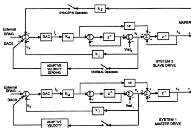
The basic model to describe the Spindle Control System is illustrated in Figure 4. Here it is observed that the system is a sampled-data system operating at one sample per revolution. Velocity error per revolution is vk
and phase error per revolution is xk• These errors are
both measured with the Timers of the Z8 and are in IJ.seconds per revolution; a Timer resolution of 1.33 IJ.seconds per count accommodates a ±O.1 % control precision. State-Space techniques are used to design the feedback structures for both the velocity and phase (MAPERR) loops.
A simple first-order velocity control loop is the basis for the architecture of the Spindle Control system. This is chosen for robustness, ease of recoverability, and functional compatibility with the IJ.-Controller. For the phase lock mode of operation (SYNCSPIN Mode) the velocity loop (with unchanged feedback coefficient) becomes a wide band minor loop with the external low-gain MAPERR loop.
NORMAL MOPE
The velocity loop is used for all basic control functions: *For NORMAL Mode operation.
*For moving from one reference velocity to another (calibration, capture).
*For all lock-on tasks.
*For all recovery operations, i.e., to bring variables out-of-tolerance back into range.
With reference to Figure
4.
in the NORMAL Mode small errors in velocity (introduced by variations in the average Drag force) are cancelled by slow integration of the velocity error to set DACO equal and opposite to the (varying) Drag force; vk then is isolated from any offsets caused by external forces.SYSTEM 2 SLAVE DRIVE
SYSTEM 1 MASTER DRIVE
Cort/erence on
[image:5.634.135.449.43.253.2]AppliedAfotionCo~ol1987
Figure 4. MasterlS/ave Sampled-Data Spindle Control System
The ~-Controller algorithm is simply:
where: k1= Vel fb Coefficient Ks=DACxKm DACO=-DRAG V(s)/I(s) = KmIs
The z-Plane pole for velocity control is designed at (z-O.6) to give a settling response of 6-8 samples.
Initial values of Km and DACO are determined by an adaptive computation upon entering the NORMAL Mode. Thus, the velocity loop in the NORMAL Mode runs free of dc velocity error while also providing a fast response to error disturbances.
SYNCHRONIZED SPINPLE MOPE (SYNCSPIN)
The velocity loop is also used to drive the MAPIN (Slave) Pulse into coincidence with the MAPOUT (Master) Pulse. When MAPIN is locked to MAPOUT, the INDEX of the Slave Drive is locked to the INDEX of the Master Drive and the Master/Slave Drives are in rotation synchronism (SYNCSPIN Mode).
As mentioned previously, the Locked Spindle feature allows parallel data transfer of N serial data streams from N synchronized Drives. Although up to 48 Slave Drives can be driven from one Master Drive, the number of Slave Drives is unlimited if MAPOUT is generated by a Host Computer. The SYNCSPIN Feature, software implemented in the ~-Controller with a negligible addition of hardware (one plug), provides a powerful system feature for the XT-8000E Drive Family which allows tailoring by the user for his speCific sytem needs (channel rate, parallel capacity, over-lapped latency, etc.)
PageS
With reference to Figure 4, the control sequence of the SYNCSPIN Mode is as follows:
* The J.L-Controller continuously monitors for MAPIN detection. If no MAPIN is detected, the Drive is defaulted as a Master Drive and then operates in the NORMAL Mode; otherwise, for MAPIN detected, the Drive is a Slave Drive operating in the SYNCSPIN Mode.
* When MAPIN is detected, the Spindle Control enters a high-speed CAPTURE Mode in which, under velocity control, the Slave INDEX is driven into the Master INDEX window region (MAP Window). The mechanics of the high speed CAPTURE Mode is to modify VRef of the Slave velocity loop to achieve a high error velocity from the nominal 3596 RPM of the Spindle, this to bring the Slave INDEX (within 1 second) from as far away as 8343 ~seconds of error to within ±20 J.LSeconds of error in the MAP \tYindow.
* When in the MAP Window, the Spindle Control automatically goes into the Phase Lock Mode, MAPERR is generated, and the Slave INDEX is locked to the Master INDEX via the algorithm identified for the Slave Drive in Figure
4.
Note that in this sequence the feedback coefficient k1 remains undisturbed. The Spindle is posted as being locked in the SYNCSPIN Mode (Spindle Locked/STATUS 8).* The ~-Controller constantly monitors vk and
.Conference on
Applied Motion Control 1987
ELECTRONIC COMMUTATION
An additional important capability offered by ~-Control!er control of a multi-phase Spindle motor is that of Electronic Commutation. For the fixed circuit of Figure 3, the Il-Controller has complete control over the commutation timing and the power driver-to-motor phase connections.
In the implementation of Electronic Commutation for the XT-8000E, it was empirically determined that a make-before-break commutation coupled with phase
delay of the commutation produced two effects:
1. Both electrical and acoustical noise were decreased by a "soft" commutation in which
two half-steps of commutation were spread over one commutation time.
2. Phasing (Timing) of the commutation allowed optimization (minimization) of the motor current (which identifies with optimization of the torque angle).
Both of these effects, under a ~-Controller regime, have clear implications for motor control both in the disk drive industry and beyond, generally, into the power industry.
5. Conclysion
Embedding of a Il-Controller into a Disk Drive Spindle control system has added new dimension to the design
and synthesis of Spindle control.
In terms of the three areas discussed in this paper, the ~-Control!er has led to a design which augments the basic Spindle control function as follows:
Diagnostics. In-Line STATUS-sensing coupled with conditional action paths assures in-spec operation of the
S~indle, p~o~ides RETRY ~apability for soft/marginal failure activity, and prOVides protection of power components (ABORT) in the event of hard failures. These same diagnostic capabilities playa role as adjunct analysis tools in the Development/Production/Field Service phases of Disk Drive manufacture via logging and interpretation of the STATUS conditions of individual Drives.
Hardware. In addition to a minimization of componentry of the Spindle control system, the packaging of the
control system electronics has been partitioned to take
advantage of future CMOS/ASIC packaging in which single chip Il-Controllers will reside in the same IC package as the anCillary I/O Circuitry. This factor is especially important relative to the cost, power, and space requirements of higher performance Drives and the smaller form-factor Drives of the future.
Pages
The ~-Controller, with its adaptive capability, offers one universal circuit to extend over the spectrum of Drives; within this concept, the Power Module is tailored to the specific Spindle power requirements for each form-factor Drive; cost optimization of the Spindle electronics/motor combination becomes clearly defined.
u-Cootroller Algorithm Design. From a control system
point of view, the basic strength of the ~-Controller in the present application is its ability to use simplistiC first-order and second-order models of the Spindle system and to augment these models with (adaptive) corrections.
As has been indicated, this philosophy leads to a control system which has the properties of being robust, of recoverability, and of fast (calibrated) response to disturbances via appropriate algorithms in the ~-Controller; implicitly, the algOrithms have redefined a complex control problem into a sequence of manageable Simple control problems. The synergism of this approach extends the ingenuity and imagination of the practicing Control Engineer.
What has not been indicated in this paper is a generic situation relating to the Control Engineer and his use of ~-Controllers. The total function and performance of the Spindle control system is focused on the coding implementation in the ~-Controller; with the fixed electronic hardware, the design realm has shifted to the domain of the Control Engineer to implement all function, performance, and change within the ~-Controller coding.
Although a complete retinue of ~-Controller tools (including advanced Il-Controller/PROM capability) have become available to the Control Engineer to take advantage of the facets of Il-Controller control discussed above, he will be challenged to use these tools effectively to respond to a Disk Drive environment of hastened development cycles, of fast turn-around in Manufacturing, and of using the most advanced motor/electronic technology, all within tight cost effective boundaries.