166-772-001
Revision
A
July 23, 1986
Xylogics
Model 772
User's Manual
YOUR PARTNER FOR PERFORMANCE.
166-772-001
Revision
A
July 23, 1986
Xylogics
Model 772
User's Manual
YOUR PARTNER FOR PERFORMANCE.
XYLOOICS 772 Tape Controller User I s Manual
LEST OF ILLUSTRATiONS ••••••••••••••••••••••••••••••••••••••••••••• viii
SECrION 1: SPECIFICATIONS
1.0 ~ •••••••••••••••••••••••••••••••••••••••••••••••••••••••• 1
1.1 tJSItG
mrs
~•.••..•••...•...•...••... .;.
1 1.1.1 Abbreviations •••••••••••••••••••••••••••••••••••••••••• 11.2 DFSI~ REI..IABn..I~ ••••••••••••••••••••••••••••••••••••••••••••• 2
1.3 mYSlCAI. ••••••••••••••••••••••••••••••••••••••••••••••••••••••• 2
1.4 ~ •••••••••••••••••••••••••••••••••••••••••••••••••• 2
1.5
...
31.6 SYSTEM ~ SPECIFICATiONS •••••••••••••••••••••••••••••••••• 3
1.7 TAPE DRIVE RELATED SPECIFICATIONS
...
41.8 VMEbus ~ SPECIFICATIONS •••••••••••••••••••••••••••••••••• 5
1.9 SOF'lWARE RELATID SPECIFICATiONS
...
51.9.1 SOftware Interface ••••••••••••••••••••••••••••••••••••• 6
1.10 ~E FEA.'lIJRFS •••••••••••••••••••••••••••••••••••••••••• 6
SECrION 2: INSTALLItG AND TmTIN:; '!HE 772
2.0
2.1
2.2
~---
..
~ •••••••••••••••••••••••••••••••••••••••••••••••••••••••• 7
~ACI{It\K; AND mSPECl'ION ••••••••••••••••••••••••••••••••••••••• 7
2.1.1 2.1.2 2.1.3 2.1.4
Inspect the Shipping carton ••••••••••••••••••••••••••••
Contents •••••••••••••••••••••••••••••••••••••••••••••••
Handling precautions ••••••••••••••••••••••••••••••••••• Inspect the 772 ••••••••••••••••••••••••••••••••••••••••
CWFIGURIOO 'llIE 772 ••••••••••••••••••••••••••••••••••••••••••••
2.2.1 2.2.2
Base Address Selection •••••••••••••••••••••••••••••••••
Bus Request and Bus Grant Lines
...
i
'OQ';:
7 7 7 7 8
9
xn.cx;ICS 772 Tape Controller User I s Manual 2.3 2.4 2.5 2.6 2.7 2.8 2.9 2.10
TABLE OF cx:NrENTS
PAGE
2.2.3 2.2.4
Parallel Arbitration •••••••••••••••••••••••••••••••••• Light Emitting Diodes
...
PRGfS AND PAIS
...
~...•...
BOARD LABELS / REVISION <nNTR(L
...
PREPARIl'G '!HE cnD?UTER SYSTEM
...
2.5.1 2.5.2 2.5.3
Backplane Jumpers ••••••••••••••••••••••••••••••••••••• card cage Slot •••••••••••••••••••••••••••••••••••••••• Power Considerations ••••••••••••••••••••••••••••••••••
10 10 11 11 11 11 11 12
PREP~ '!HE T.APE DRIVE •••••••••••••••••••••••••••••••••••••• 12
2.6.1 Drive Unit Select
...
INSTALL AND CABLE '!BE 772
...
2.7.12.7.2
...
Install the 772cable the Subsystem
...
INITIAL TESTS
...
2.8.1 2.8.2 2.8.3
Tape Drive Diagnostics
Power-up and Self Test
...
...
Drive On-line...•...
DIJl,Gl\()STICS
...
CABLIt{; MULTIPLE DRIVES
...
-... .
12 12 12 13 13 13 13 14 14 142.10.1 Unit Select ... 15
SEcrION 3: '!HE 772 RmISTERS
3.0
3.1
3.2
3.3
3.4
~ ••••••••••••••••••••••••••••••••••••••••••••••••••••••• 16
rops
ADDRESS RmISTERS •••••••••••••••••••••••••••••••••••••••• 16lOPS ADDRESS IDDIFIER / PRIORITY lOPS REx;ISTER
...
16~OL AND STATUS REGISTER ••••••••••••••••••••••••••••••••••• 17 3.3.1
3.3.2
...
Control Register (Write)Status Register (Read)
...
17 19FAT.AI.. ERROR REGISTER. ••••.•••••••••••••••••••••••••••••••••••••• 21
ii
[image:6.621.93.536.80.704.2]XYLOOlCS 772 Tape Controller User I s Manual
TABLE OF <nl1'ENTS
PAGE
SEcrlON 4: lOPB DESOUPl'lON
4. 0 ~. • . . • • • • • • • . • • . . • • . . • . . • . . . • • • . . • • . . . • . . . • • • • . . . . .• 22
4 .1 sr~ IOPB •••••••••••••••••••••••••••••.••••••••••••••••••• 22
4.1.1 4.1.2 4.1.3 4.1.4 4.1.5 4.1.6 4.1. 7 4.1.8 4.1.9 4.1.10 4.1.11 4.1.12 4.1.13 4.1.14 4.1.15 4.1.16 4.1.17
roPB Byte 0 (Command) ••••••••••••••••••••••••••••••••• 23
lOPB B¥te 1 (Status Byte 1) ••••••••••••••••••••••••••• 24 IOPB Byte 2 (Status Byte 2) ••••••••••••••••••••••••••• 24 IOPB Byte 3 (status Byte 3) ••••••••••••••••••••••••••• 25 IOPB Byte 4 (Subfunction) ••••••••••••••••••••••••••••• 26
roPB B¥te 5 (Unit) ••••••••••.•••.••••••••••••••••••••• 28
IOPB Byte 6 (Interrupt Level) ••••••••••••••••••••••••• 28 IOPB Byte 7 (Interrupt Vector) •••••••••••••••••••••••• 29 IOPB Bytes 8 and 9 (Count) •••••••••••••••••••••••••••• 29 IOPB B¥te A (Last Error) •••••••••••••••••••••••••••••• 29 IOPB Byte B (Error Count) ••••••••••••••••••••••••••••• 29 IOPB Bytes C and D (Actual Count) ••••••••••••••••••••• 29 IOPB Byte E (Data Address Modifier) ••••••••••••••••••• 30 IOPB Byte F (Next IOPB Address Modifier) •••••••••••••• 30 IOPB B¥tes 10 Through 13 (OMA Data Address) ••••••••••• 31 IOPB Bytes 14 Through 17 (Next IOPB Address) •••••••••• 31 IOPB Bytes 18 and 19 (IOPB Checksum) •••••••••••••••••• 31
4.2 CONTROLLER PARAMETERS IOPB •••••••••••••••••••••••••••••••••••• 32
4.2.1 4.2.2 4.2.3 4.2.4 4.2.5 4.2.6 4.2.7 4.2.8
IOPB Byte 8
IOPB B¥te 9
IOPB B¥te A IOPB Byte B
(Controller Parameters A) (Controller Parameters B) (Controller Parameters C) (Controller Parameters D)
·
... .
· ... .
·
... .
·
... .
IOPB Byte E (Controller TYPe) •••••••••••••••••••••••••
IOPB Bytes 10 and 11 (EPROM Part Number) •••••••••••••• IOPB Byte 12 (Revision) ••••••••••••••••••••••••••••••• IOPB Byte 13 (Subrevision) ••••••••••••••••••••••••••••
33 34 35 36 36 37 37 37
4.3 WRITE DRIVE PARAMETERS IOPB ••••••••••••••••••••••••••••••••••• 38
4.4 4.3.1 4.3.2 4.3.3 4.3.4 4.3.5
IOPB Byte 8 (Drive Parameters A) •••••••••••••••••••••• 39 IOPB Byte 9 (Drive Parameters B) •••••••••••••••••••••• 40 IOPB Byte 10 (Data Busy Timer) •••••••••••••••••••••••• 42 IOPB Bytes A Through D (Density Select) ••••••••••••••• 42 IOPB B¥te E (Variable IRG) •••••••••••••••••••••••••••• 43
CCJ.1MAND PASS 'lHROOGH TO DRIVE IOPB
...
444.4.1 4.4.2
IOPB Byte 8 (B¥te Count) •••••••••••••••••••••••••••••• 45 IOPB Bytes A Through D (Tape Command) ••••••••••••••••• 45
[image:7.618.78.522.106.747.2]XYLOOICS 772 Tape Controller User I s Manual
TABLE OF <rm'EN.lS
PAGE
SEcrION 5:
5.0
5.1
5.2
5.3
5.4
5.5
5.6
5.7
5.8
5.9
5.10
5.11
5.12
5.13
~ ••••••••.••.••••••.•..•••.•.••..•.••.•...•..•..• 46
5.0.1 5.0.2 Setting Up The Command Completing The Command
...
...
46 46 W OPERl\TION •••••••••••••••••••••••• -. • • • • • • • • • • • • • • • • • • • • • • • •• 47 ~TE DATA •••••••••••••••••••••••••••••••••••••••••••••••••••• 48 READ DATA. ••••••••••••••••••••••••••••••••••••••••••••••••••••• 49 POSITION...
505.4.1 Position Subfunction Codes
...
51DRIVE RESET
...
525.5.1 Drive Reset Subfunction COdes
...
53WRITE PARAMETERS
...
545.6.1 write Parameters Subfunction Codes
...
54READ PARAMETERS
...
565.7.1 Read Parameters Subfunction Codes
...
56~ED WRITE •••••••••••••••••••••••••••••••••••••••••••••••• 59 5.8.1 Extended Write Subfunction Codes
...
59.EX'I'mDED READ ••••••••••••••••••••••••••••••••••••••••••••••••• 62 5.9.1 Extended Read Subfunction Codes
...
62DI.l-IJGWSTICS
...
6~5.10.1 Diagnostic Subfunction Codes
...
63.ABORl' ••••••••••••••••••••••••••••••••••••••••••••••••••••••••• 66 SET DRIVE PARAMETERS
...
675.12.1 Set Drive Parameters Subfunction Codes
...
68COMMAND PASS THROUGH TO DRIVE ••••••••••••••••••••••••••••••••• 69
iv
[image:8.618.69.513.65.703.2]XYLCX;ICS 772 Tape Controller User's Manual
TABLE OF CXNl'EN.15
SEcrION 6: ERROR PROCESS]N;
6.0 6.1 6.2 6.3 6.4 6.5 6.6 6.7 6.8
GENERAL
...
70ERROR REPORl']N;
...
70 6.1.1 IOPB Byte 1 (Status Byte 1)...
70REOOJERY PRCX:EIXJRE:.s ••••••••••••••••••••••••••••••••••••••••••• 75
6.2.1 6.2.2 6.2.3 6.2.4 6.2.5 6.2.6
Non-re~ab1e Programnling Errors
...•••..•.•...
Successfully Recovered Soft Errors •••••••••••••••••••• Hard Errors Requiring Retry ••••••••••••••••••••••••••• Hard Errors Requiring Reset and Retry ••••••••••••••••• Miscellaneous Errors...
You're Lost...
75 75 76 80 80 81
lGOORIl'J(; ERroRS ••••••••••••••••••••••••••••••••••••••••••••••• 81
FA~ ERROR CODE DESCRIPTIONS ••••••••••••••••••••••••••••••••• 82
ERRORS DUR.nl; ClIAINED OR QUEUED OPERATIONS
...
82 [image:9.621.71.506.116.694.2]~]N; •••••••••••••••••••••••••••••••••••••••••••••••••••••• 82
...
83 ERROR REPORl']N; HIERARCHY ••••••••••••••••••••••••••••••••••••• 83SEcrION 7: A 'lUTORIAL IN PROORAMMm; '!HE 772
7.0
7.1
7.2
GENERAL ••••••••••••••••••••••••••••••••••••••••••••••••••••••• 84
ltD OPERATION •••••••••••••••••••••••••••••••••••••••••••••••••• 84
7.1.1 7.1.2 7.1.3 7.1.4 7.1.5 7.1.6
Allocating Memory For An IOPB ••••••••••••••••••••••••• Point the 772 to the IOPB ••••••••••••••••••••••••••••• Starting the Operation •••••••••••••••••••••••••••••••• 772 Operation ••••••••••••••••••••••••••••••••••••••••• Command Completion •••••••••••••••••••••••••••••••••••• Returned Values
...
85 85 85 85 85 86
READ CONT.ROLLER PARAMETERS •••••••••••••••••••••••••••••••••••• 86
7.2.1 7.2.2 7.2.3
Execute the IOPB ••••••••••••••••••••••••••••••••••••••
772 Operation •••••••••••••••••••••••••••••••••••••••••
'ltle Returned lOPB •••••••••••••••••••••••••••••••••••••
-v-86 87 87
XYLOGICS 772
Tape
Controller User's Manual7.3
7.4
7.5
7.6
7.7
7.8
TABLE OF CDNTENTS
PN:;E
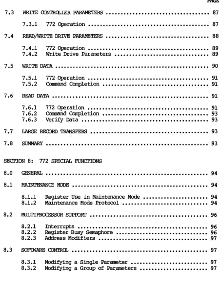
WRITE CONTRCLLER PARAMETERS
...
87 7.3.1 772 Operation ••••••••••••••••••••••••••••••••••••••••• 87READ/WRITE DRIVE PARAMETERS
...
88 7.4.17.4.2 772 Write Drive Parameters •••••••••••••••••••••••••••••••• Operation ••••••••••••••••••••••••••••••••••••••••• 89 89
WRITE DATA •••••••••••••••••••••••••••••••••••••••••••••••••••• 90
7.5.1 7.5.2
772 Operation •••••••••••••••••••••••••••••••••••••••••
Command ~letion ••••••••••••••••••••••••••••••••••••
91 91
READ DATA ••••••••••••••••••••••••••••••••••••••••••••••••••••• 91
7.6.1 7.6.2 7.6.3
772 Operation ••••••••••••••••••••••••••••••••••••••••• 91
Cbrnmand ~letion •••••••••••••••••••••••••••••••••••• 93
Veri~ Data ••••••••••••••••••••••••••••••••••••••••••• 93
I..ARGE REXlJRD 'IRANSFERS •••••••••••••••••••••••••••••••••••••••• 93
~y ••••••••••••••••••••••••••••••••••••••••••••••••••••••• 93
SEcrION 8: 772 SPECIAL FUNcrIONS
8.0
8.1
8.2
8.3
GmERAI., ••••••••••••••••••••••••••••••••••••••••••••••••••••••• 94
MAINTENANCE IDDE
...
948.1.1
8.1.2
Register Use in Maintenance Mode •••••••••••••••••••••• 94 Maintenance Mode Protocol ••••••••••••••••••••••••••••• 94
MULTIPROCESSOR SUPOORr
...
8.2.1 8.2.2 8.2.3
Interrupts
...
Register Busy semaphore...
Address Modifiers...
96
96 96
97
SOE"IW'AR.E <DNIR.(l, •••••••••••••••••••••••••••••••••••••••••••••• 97
8.3.1 8.3.2
Modi~ing a Single Parameter •••••••••••••••••••••••••• Modifying a Group of Pa~ameters •••••••••••••••••••••••
vi
97 97
[image:10.621.79.530.95.686.2]XYLOOICS 772 Tape Controller User I s Manual
8.3.3 8.3.4 8.3.5
Parameter Reference Point ••••••••••••••••••••••••••••• 97 Setting Parameters at Boot Time ••••••••••••••••••••••• 98 Validate Current Parameters ••••••••••••••••••••••••••• 98
8. 4 SCA.~GAilIER. • • • • • • • • • • • • • • • • • • • • • • • • • • • • • • • • • • • • • • • • • • • • • •• 98
8.5
8.6
·8.4.1 8.4.2 8.4.3
Scatter/Gather Link List •••••••••••••••••••••••••••••• 98 Setting Up a Scatter/Gather Transfer •••••••••••••••••• 99
772 Operation •••••••••••••••••••••••••••••••••••••••• 100
Il-tA 'lHRCYI'lLE / 'lHRCYI'lLE DEAD TIME
...
101BLACK HOLE TRANSFERS
...
1018.7 PRIORITY IOPBs ••••••••••••••••••••••••••••••••••••••••••••••• 101
8.7.1 8.7.2 8.7.3
Executing a Priority lOPB •••••••••••••••••••••••••••• 102 Executing a Priority Chain ••••••••••••••••••••••••••• 102 772 Response to a Priority lOPB (Chain) •••••••••••••• 102
8 • 8 lOPB OiEO<SUM •••••••••••••••••••••••••••••••••••••••••••••••• 102
8.9 AlJ'I'<l-1ATIC STREAMOO: RItll OOFFERS •••••••••••••• Go • • • • • • • • • • • • 102
8.10 <nlMAND PASS mRClJGH
...
104 8.11 INl'ERRUPI' AT END OF ClIAIN...
1048.12 RELEASE ON REQUEST ••••••••••••••••••••••••••••••••••••••••••• 104
SECl'ION 9: 772 ilIEORY OF OPERATION
9. 0 ~. • • • • • • • • • • • • • • • • • • • • • • • • • • • • • • • • • • • • • • • • • • • • • • • • • • • •• 105
SEC'rION 10: 772 DRIVE INrERFACE
10. 0 G~AAI... • • • • • • • • • • • • • • • • • • • • • • • • • • • • • • • • • • • • • • • • • • • • • • • • • • • •• 106
10.1 PEm'OC INTERFACE SIGNAI.S ••••••••••••••••••••••••••••••••••••• 106
10.2 SPECIAL SIGNAL DEFINITIONS
...
10710.3 VMEbus INTERFACE SIGNAI.S ••••••••••••••••••••••••••••••••••••• 108
TImE}{ • • • • • • • • • • • • • • • • • • • • • • • • • • • • • • • • • • • • • • • • • • • • • • • • • • • • • • • • • • • • • • 112
XYLOOIQ) 772 Tape Controller User I s Manual FIGURES TABI..ES 2-1. 2-2. 2-3. 2-4. 2-5. 2-6. 5-1. 6-1. 6-2. 7-1. 7-2. 7-3. 7-4. 7-5. 7-6. 8-1. 8-2. 9-1. 2-1. 2-2. 3-1. 3-2. 4-1. 4-2. 4-3. 4-4. 4-5. 4-6. 4-7. 4-8. 4-9. 5-1. 6-1. 6-2. 8-1. 8-2. 8-3. 8-4. PJQ:
772 - Component Location •••••••••••••••••••••••• 8
Base Address Jumper Block ••••••••••••••••••••••• 9 Jumpering Bus Request and Bus Grant Levels ••••• 10 Sample Part Number ••••••••••••••••••••••••••••• 11 Cabling Multiple Drives •••••••••••••••••••••••• 15 Dai~-chain cable •••••••••••••••••••••••••••••• 15
'lY'Pical Tape. FOI'Illat ••••••• e·e • • • • • • • • • • • • • • • • • • • 51
Write Error Beyond Retry ••••••••••••••••••••••• 76 Error Reporting Hierarchy •••••••••••••••••••••• 83 Sample NOP lOPS •••••••••••••••••••••••••••••••• 84 Sample Read Controller Parameters IOPB ••••••••• 86
Sample Write Controller Parameters lOPS •••••••• 88 Sample Write Drive Parameters lOPS ••••••••••••• 89
Sample Write Data IOPB ••••••••••••••••••••••••• 90
Sample Read Data IOPB •••••••••••••••••••••••••• 92
Scatter/Gather Transfers •••••••••••••••••••••• 100 Disk To Tape Transfer USing Ring Buffers •••••• 103 772 Block Diagram ••••••••••••••••••••••••••••• 105
Base Address Selection •••••••••••••••••••••••••• 9 PR<Jt1/PAL Part Number and Location •••••••••••••• 11 Register Offsets ••••••••••••••••••••••••••••••• 16 Fatal Error Codes •••••••••••••••••••••••••••••• 21 Subfunction Code Classes ••••••••••••••••••••••• 26 772 CorrInand/Subfunction Codes •••••••••••••••••• 26 AlO Response Times ••••••••••••••••••••••••••••• 34 Throttle Values •••••••••••••••••••••••••••••••• 36
Controller TYPe Codes •••••••••••••••••••••••••• 36
Density Selected Via Cclnmand Lines ••••••••••••• 40
Density COdes •••••••••••••••••••••••••••••••••• 41
Data Busy Timeout •••••••••••••••••••••••••••••• 42 Density Selection Codes •••••••••••••••••••••••• 43 772 Oommand Completion ••••••••••••••••••••••••• 46 Reoove~ Codes ••••••••••••••••••••••••••••••••• 71
Summa~ of Completion Codes •••••••••••••••••••• 71 Register Use in Maintenance Mode ••••••••••••••• 94 Scatter/Gather Link List ••••••••••••••••••••••• 98
Link List Field Values ••••••••••••••••••••••••• 99 Throttle Dead Time Values ~ •••••••••••••••••••• 101
viii
XYLOOICS 772 Tape Controller User I s Manual
SECl'IOO 1: SPECIFIC'ATIWS
1.0 GENERAL
'!he Xylogics Model 772 Tape Controller couples up to eight Pertee-formatted Interface 1/2-inch tape drives to VMEbusl systems.
1.1 USING THIS MANUAL
1.1.1
Section 1 describes the 772 specifications; Section 2 details how to install the controller; Section 3 describes the 772 registers; Section 4 describes the IOPBs; and Section 5 describes the 772 canmands. Section 6 describes error processing; Section 7 is a programming tutor ial ; Section 8 explains the 77 2 I s special
functions; Section 9 details the 772 theory of operation; and Section 10 includes general maintenance aids.
Abbreyiations
'!his manual uses the following mnemonics: AlO
AlOP AlOR
AM ASS ADD
BHT
<lIEN ClUO
CRBS crYP
DFLT
DRRDY ERRS FERR
FIFO
H
ICS I/O IOPB
!RAM LED
MMA
MM
Add New IOPB AlO Pending
AlO Response Time
Address Modifier Auto-streaming Select Auto-update
Black Hole Transfer Chain Enable
Clear Remove IOPB Clear Register Busy Controller Type
Drive Fault Drive Ready Error surrmary
Fatal Error
First In/First Out Buffer
Notation for Values Expressed in Hexadecimal IOPB Checksum
In/Out
In/Out Parameter Block Battery Backed-up RAM
Light Emitting Diode Maintenance Mode Active Maintenance Mode
1. VMEbus is a trademark of the VMEbus International Trade Association.
XY.LC'GICS 772 Tape Controller User I s Manual
1.1.1 Abbreyiations (continued)
NPRM Nan-privileged Register Mode
PNUM Prom Number PRIO Priority IOPB
RBS Register Busy Semaphore RIO Remove IOPB
RMM Register Maintenance Mode ROR Release On Request
SGM Scatter/Gather Mode 'lDT Throttle Dead Time
THRO Throttle '!MOD Transfer Mode
WPT Write-protect 64KB 65,536 Bytes
1.2 DESIGN RELIABILITY
Xylogics implements the following features to mdnimdze the likelihood of product failure:
o Design for worst
case
voltage and temperature. o Extensive evaluation testing.o Low parts count through extensive use of custan LSI. o Buffer parity for continuous error checking.
o Low-stress design on all components. o All components burned-in.
o One card; resides in backplane or expansion chassis.
o Controller is power-cycled under theonal stress during test.
1.3 PHYSICAL
PACKAGING -- The 772 resides on one printed circuit board.
DIMENSIONS -- The 772 is a 2 ~ 2 Eurocard standard; it measures 9.2-inches high by 6.3-inches deep (233.35
mm
by 160mm).
The 772 is identical in form-factor to the standard VME (dual high-dual wide) printed circuit board.SHIPPllt; WEIGHT -- 3 fX)unds (1.4 kg).
CONNECTORS -- There are two 50-pin connectors on the edge of the board facing out; they protrude through the optional front panel.
FRCNI' PANEL -- Xylogics offers the 772 with an optional front panel.
1.4 ENVIRrnMENTAL
The 772 envirorrnental requirements are 0 to 550 C, with a maximum relative humidity of 90% (without condensation). Air flow across the board must maintain a maximum tanperature differential of 70 C to prevent hot sfX)ts.
XYLCX;ICS 772 Tape COntroller User I s Manual
1.5 ELECI'RIC'AL
POiER - '!he 772 uses 4.2 amperes at +5 volts DC (VDC).
TOLERANCE - Voltages must be within plus or minus five percent (4.75 to 5.25).
GROUNDING -- Common earth ground must be established between the tape drives and the CPU chassis, backplane, and expansion cabinets.
1.6 SYSTEM RELATED SPECIFICATIONS
DATA TRANSFER MODES - The 772 transfers data in Word or Longword mode. The 772 may use byte transfers to align subsequent transfers on word boundaries.
I/O ADDRESSING CAPABILITY - The 77 2 decodes byte addresses for its on-board registers.
DATA BUFFERING -- The 772 has a FIFO buffer that is 8k-bytes long and incorporates parity error detection. Data can be put into one end of the FIFO and simultaneously removed at the other end; there are no delays associated with filling and emptying the buffer.
~ BUFFER - '!he 772 reads corrnrands into a separate buffer that holds up to fifteen full commands (IOPBs); this minimizes processor intervention and optimizes controller decode overhead. '!he 772 also stores up to fifty IOPB addresses.
STA'lUS LEOs - The 772 implements two status LEOs. Ll (BSY) indicates the controller is active; L2 (ERR) indicates the on-board diagnostics did not complete successfully, or a fatal error occurred.
MULTIPROCESSOR SUPPORT - '!he 772 has a built-in register control semaphore. This flag allows multiple processors to share the 772 register set. See Section 8.2 for more information.
SCATl'ER/GA'IHER - The 772 supports Scatter/Gather Read and Write cornrrands. The controller can gather data from various memory locations and transfer it to the buffer for use in a Write command; it can scatter the data out fram the tape drive to the appropriate memory locati~ns with a Read cornrrand. To execute a scatter/gather, software issues a normal Read or Write cornrrand along with a IXvIA
list that contains a memory address and the number of 16-bit words to transfer to/fram that location. The smallest granularity of scatter/gather is one 16-bit word.
PRIORITY IOPBs - The 772 executes priority IOPBs qver all IOPBs in its command buffer, except for the one in process.
BLACK HOLE TRANSFERS - '!he 772 may transfer all the IXvIA data into, the same bus address without incrementing the address at each IXvIA.
XYLOOICS 772 Tape Controller User's Manual
1.6 SYSTEM RELATED SPECIFICATIONS (continued)
SOFlWARE SUPPORI' - Sample software driver supplied for use in UNIX2 based systems (source included).
SOFlWARE cnNTROL -- Software can program the 772 for use with various drive configurations, controller parameters, and controller options.
1.7 TAPE DRIVE RELATED SPECIFICATIONS
TAPE INTERFACE - Pertec-formatted Interface.
TAPE DATA TRANSFER RATE - '!he 772 supports tape drive transfer rates from 20 kilobytes per second (I<BS) to 2 megabytes per second (MBS) • '!he tape data transfer rate is a function of tape speed, densi ty, and in certain cases the tape cache speed.
NUMBER OF TAPE DRIVES -- '!he 772 supports up to eight tape drives, including mixed speeds, densities, and types. .
DRIVE PARAMETER PASS 'lllROOGH - '!he 772 supports any tape drive manufacturer's command set via a special command. The 772 allows software to directy manipulate the tape command lines with this special corranand.
READ/WRITE CXNI'INlnJS DATA - The 772 can read or write continuous streams of data, up to the the entire tape length, by linking the data addresses together with a special command. '!his feature is extremely useful in all applications requiring a large amount of data collection.
AlJ'IO.1ATIC STREAMm.; mNTROL - To successfully maintain Streaming mode, software must provide cormnands and data to the 772 within the tape drive's prescribed reinstruct window. I f software does not meet this time, and the drive is set for Streaming mode, the drive repositions (causing a performance loss). '!he 772 autanatica1ly shifts the tape drive into Non-streaming mode if software does not meet the reinstruct window, reducing the performance loss to a ml.nJ.mum. I f software meets the reinstruct window, the 772 switches the drive back into Streaming mode.
ERROR DETECl'ION AND RETRY - '!he 772 allows a great deal of flexibility in dealing with errors, depending on the application. Available options include multiple error reporting, autanatic retry on Read or Write operations, and Ignore Read or Write errors. '!he 772 reports the actual nurnberof bytes transferred, file marks skipped, records sp:iced, or retries attempted, during Read, Write, and Position operations.
2. UNIX is a trademark of AT&T.
XYLOOICS 772 Tape Controller User I s Manual
1. a VMEbus RELATED SPECIFICATIONS
'mANSFER MIDE - Direct Memory Access (lEA).
IJm 'lBR0PlLE cx:NIRCL - Each tine the 772 becanes bus master, it executes IJm transfers to or fran the buffer up to the max throttle parameter or the number of bytes/spaces available in the buffer.
IJm DATA TRANSFER RATE - '!he 772 transfers data at a rate of up to 10 MBS; this rate requires Longword mode transfers and a system memory that responds wi thin 200 nanoseconds.
lEA PROCFSSOR - !]he 772 has a custan IJm processor that allows dual channel operation (speeding up the IJm by reducing the inter-transfer overhead).
IJm DFAD TIME - !]he 772 supports a programmable Il<1A dead tine between throttle bursts. 'Ibis prevents the 772 fran taking over the bus and allows tine for other Il<1A devices to access the bus.
DATA TRANSFER LIMIT - Data transfer length, fran 1 to 65,536
bytes. '!he 772 supports unlimited data transfer lengths via a special camnand.
BUS CXM>ATmILITY - '!he 772 is canpatible with the standard VMEbus.
ADmESSnx; CAPABILITY - Full 32-bit support. '!he 772 supports Master A32, and Slave A16, as per the VMEbus Specification. As a slave, the 772 respoms to Address Modifiers 29H and 2DH.
DATA WII11H - '!he 772 supports 016 and 032 as per the VMEbus Specification Manual. '!he 772 transfers data one byte, one word, or one byte and one word at a tine until the transfer aligns with a word or longword boundary.
RE:LF.ASE GJ REOJEST - '!he 772 releases the bus at the request of other peripheral devices.
RE:LF.ASE WHEN OONE - '!he 772 releases the bus after each bus access.
BUS REOJEST LEVELS - '!he 772 supports four bus request levels.
IN'l'ERIDPl' PRIORI'lY - Software programmable interrupt level and vector.
1.9 SOF'IWARE RELATED SPECIFICATIONS ,
CCNIRCLLER I/O PARAMETER BLOCK (IOPB) LENG'm - 26 bytes.
CCNIRCLLER REGISl'ERS - Seven a-bi t I/O Registers; byte or word
addressable. Only eight bits respond during word access.
XYLOOIQ) 772 Tape Controller User I s Manual
1.9 SOF'IWARE RELATED SPECIFICATIONS (continued)
1.9.1
DIAGIDSTIC SUPPORl' - Canprehensi ve set of stand-alone diagnostics written in IC' are available.
SOF'IWARE INTERFACE - '!he 772 supports a high level software interface that allows system software to use the same method to add IOPBs to a chain while the controller is busy or while it is free.
Software Interface
The software interface includes seven byte-wide registers. Four of these bytes comprise the VME Address Register, the fifth byte is the Address Modifier Register, the sixth byte is the Control and Status Register (CSR), and the last byte is the Fatal Error Register (FER). The CSR includes two bits that are very important to IOPB processing: Add IOPB (AIO) and Remove IOPB (RIO).
The IOPB is a block of cOIIll'[aIld and status information; it includes the bus address, and the type of operation to be performed. 'Dle software driver sets up the IOPB in user nanory, sends the IOPB address to the VME Address Registers, and sets the AIO bit. After the 772 receives the IOPB address, it resets AIO. 'Dle 772 then performs the IOPB function and, upon completion or error, updates the IOPB status and sets RIO. The VME Address Registers point to the complete IOPB; the software driver reads the address, and resets RIO.
Software may add IOPBs to the queue, providing AIO is reset, by
writing the lOEB address to the address registers, and setting AIO (regardless of the 772's busy status).
1.10 PRmRAMMABLE FEAWRES
o Software Controlled Interrupts or Polled operations.
o Software Programmable DMA Parameters.
o Software Controlled Register Response.
o Software Controlled Transfer Retry/Correction.
XYLOOICS 772 Tape Controller User I s Manual
SEcr'IOO' 2: INSTALLm:; AND T&STm:; mE 772
2.0 GENERAL
2.1
2.1.1
2.1.2
2.1.3
2.1.4
Section 2 describes how to unpack, configure, install, and test your 772 controller.
UNPACKIJ:\X; AND INSPEcrION
Inspect .tm ShiP,Qing carton
Inspect the carton for possible shipping damage. If you deter.mine there is damage, do not unpack the unit. Notify Xylogics and the freight carrier immediately.
If no damage is visible, carefully unpack the 772. Save the carton and other packing material for possible later use.
Contents
The 772 is a single printed circuit board. Optional items include a manual and/or software on a floppy diskette, or 1/2-inch magnetic tape.
If any items are missing or damaged, please contact Xylogics at one of the following telephone numbers.
United States:
United Kingdom (Slough):
Handling Precautions
(617) 272-8140 44-753-78921
Observing proper handling precautions ~1nuzes the risk of damaging the 772 with electrostatic discharge. When transporting the 772, use an antistatic bag, antistatic bin, or the original shipping carton and packing material. Personnel handling the 772 should observe proper grounding methods including, but not limited to, wrist bands, heel straps, and antistatic mats.
The 772 has a non-volatile memory circuit that employs a lithium battery (at location F6). Do not expose this device to excessive heat (greater than 1250 C) as it may ignite or explode.
Inspect ~ Tl2.
Inspect the 772 for socketed parts that may have loosened during shipment. Make sure all parts are firmly seated in their sockets. If any parts must be reinserted, observe proper orientation.
XYLOOICS 772 Tape Controller User I s Manual
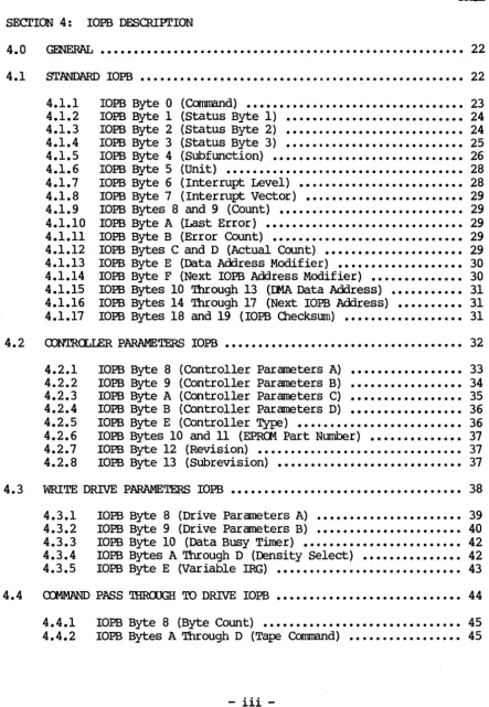
2.2 mwIGtJR]N; THE 772
You can configure the 772 with several jumper options. '!he
[image:20.627.89.533.115.695.2]following subsections describe these options.
...
,..
..J
c
o
,..
~
:::::
U
. -..
~
i
;: r..
•
I •
~
i
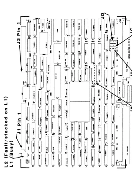
FIGURE 2-1. 772 - <XJo1PCHlIlr I.()CATIcm
Rev. A. July 23, 1986 8
<C
XYLOGICS 772 Tape Controller User's Manual
2.2.1
2.2.2
~ Address Selection
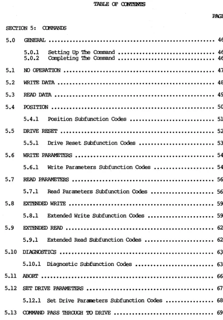
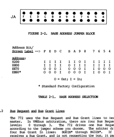
Jumper block JA controls the base address. Table 2-1 shows how to set the jumpers for corraoonly used base addresses. Inserting a jumper makes the 772 respond to a 0 on that address line; removing a jumper makes the 772 respond to a 1. Connect the jumper between similar pin numbers on each block. (The 772 uses bits 1 through 3 to determine which register is being accessed.) The 772 is an Al6
Slave, and responds to address modifier 0200, and optionally 29H.
JA
•
f E D•
•
•
• •
•
•
C•
•
B•
•
A•
•
9•
• •
8•
7•
•
6•
•
5FIGURE 2-2. BASE ADDRESS JUMPER BLOCK
Address Bit/
•
4•
Screen Label
-->
F E D C B A 9 8 7 6 5 4Mdr.:e~~:
0200 I I I I I I 0 I I I I I 0800 I I I I 0 I I I I I I I EE70 0 0 0 I 0 0 0 I I 0 0 0
EE60* 0 0 0 I 0 0 0 I I 0 0 I
o
= OUt; I=
In;* Standard Factory Configuration
TABLE 2-1. BASE ADDRESS SELECTICE
~ ~st .and Bwl Gr.:ant Lines
'!he 772 uses the Bus Request and Bus Grant lines to become bus master. In VMEbus arbitration, there are four Bus Request/Grant levels: 0 through 3. '!he 772 drives one Bus Request line according to the jumper scheme you choose. '!he arbiter drives the four Bus Grant In lines: BGOIN* through BG3IN*. If the 772 receives a Bus Grant, and is not requesting the bus, it passes the grant by driving the appropriate Bus Grant Out line: BGOOOT* through BG300T*.
[image:21.618.94.487.202.673.2]XYLOOICS 772 Tape Controller User I s Manual
2.2.2
2.2.3
2.2.4
.B.I.m ReQuest .anQ .BuQ Grant Lines (continued)
Select a Bus Request level by jumpering one Bus Request (BRO* through BR3*), one Bus Grant In, and one Bus Grant Out line to match the selected request level. Jumper the remaining Bus Grant
In/Out lines so that the incoming signal passes through the board (i.e., jumper BGxIN* to BGxaJT*, where x represents the remaining Grant levels).
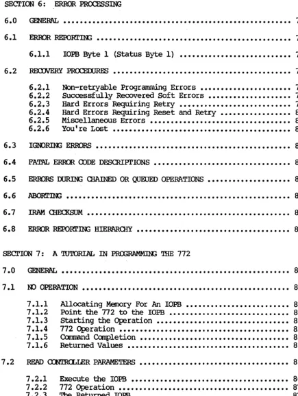
For example, Figure 2-3 shows the jumpering scheme for level 0 (Figure 2-3A shows the jumper blocks as they actually appear on the board; 2-3B is labeled for this example): jumper JBl to JBS; then jumper JCl to JC5, and JDl to JDS. Jumper the remaining Grant levels from JC6 to JD2, JCl to JD3, and Jea to JD4. Factory configuration: Bus Request Level 3.
Same
VME
processor only support Bus Request Level 3.BUS ROST BGIOUT BG/IN
·0·
·0· ·0·
.,
.
.
,
.
.
,.
·2- -2-
-2-·3- -3·
-3-BR OUT IN
L-BG ---1 J6 JC JD
LEVEl
o
I
2
3
Figure 2-3A. Actual Board Layout Figure 2-3B. Sample Jumpering Scheme
FIGURE 2-3. JOMPER]J:l; BUS ~ AND BUS GRANT LEVELS
Parallel Arbitration
If you are using the 772 in parallel arbitration, and the Bus Grant Out lines must be isolated from the next slot I s Bus Grant In lines, remove all jumpers between JC 5-8 and JD 1-4 (See Figure 2-3B).
Light Flnitting Diodes
'!be 772 has two light emitting diodes (LEOs). IJ. (BSY) is the Busy
LED (it is located closest to the printed circuit board). L2 (ERR)
is the Error LED (it straddles Ll). When L2 is on, SYSFAIL is asserted on the VMEbus.
XYLCX2ICS 772 Tape Controller User I s Manual
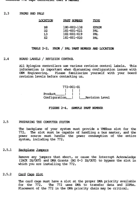
2.3 PRCMS AND PALS
LOe'ATION
B8 D2 L3
E2
~ NUMBER
180-002-138 181-001-021 181-001-019 181-001-020
EPROO
PAL PAL PAL
TABLE 2-2. PR<Jt1 / PAL PART NUMBER AND LOC'ATION
2.4 BOARD LABELS / REVISION CONTRCL
All Xylogics controllers use various revision control labels. This information is important when discussing configuration issues with OEM Engineering. Please familiarize yourself with your board revision levels before contacting us.
772-001-01
I I I
Product I I I
Configuratio~1 l---Revision Level
FIGURE 2-4. SAMPLE PART NUMBER
2.5 PREPARIN; 'IHE ro1RJTER SYSTEM
2.5.1
2.5.2
The backplane of your systen rust provide a VMEbus slot for the 772. 'Ihe slot must be capable of handling a bus master, and the power source must handle the power consumption of the entire systen, including the 77 2.
Backplane Jurtpers
Remove any jumpers that short, or cause the Interrupt Acknowledge (IAO< IN/OOT) and Il4A Grants (BG 0-3 !N/aJT) to bypass the slot in which you are installing the 772.
The card cage must have a slot at the proper Il4A priority available for the 772. 'Ihe 772 uses Il4A to transfer data and IOPBs. Placement of the 772 in the DMA priority chain may be critical.
[image:23.621.71.549.32.729.2]XYLOOICS 772 Tape Controller User I s Manual
2.5.2
2.5.3
.cam
~.sJ.Qt (continued)'!he amount of bus bandwidth it uses will be high at times; this may affect other boards in the system. Likewise, other boards may not allow enough time for the 772 to IJIIA enough data to keep up with the tape; consider this when choosing a slot. If the 772 does not get a high enough priority, then its IJIIA falls behind what the tape requires, and the tape repositions. If the 772 priority is high, it gets enough IJo1A time, but other boards having insufficient buffers may starve from lack ofDMA time. '!he priorities must be balanced for your system to work properly.
Power Considerations
The 772 affects the power consumption of the entire computer system. '!he 772 uses 4.2 amperes of +5 volts OC (4.75 to 5.25
volts) for all logic. Be sure the power supply can handle the entire power load. Readjust the voltages AFTER plugging in the
772. A power supply that is just adequate may cause intermittent
and unusual problems due to noise generated ~ occasionally going into overcurrent protection.
2.6 PREPARIN; THE TAPE DRIVE
2.6.1
2.7
2.7.1
Unpack and configure the drive for use with the 772. '!his may entail setting up such parameters as formatter address, unit select, remote density select, r~ delay, etc. Consult the drive
manual for the exact method for configuring your drive.
Drive .unit Select
A switch on the front of the drive, or switches on one of the drives internal circuit cards, selects the drive unit number and formatter address. '!he 772 accesses drives with unit numbers ranging fran 0 through 3, and formatter addresses fran 0 through 1
(allowing addressing up to eight drives). Pertec-formatted interface drives require one formatter card (embedded in one drive) for every four tape drives.
INSl'ALL AND CABLE '!HE 772
Instal 1 .the i l l
Double check the jumpering. Place the 772 into the canputer card cage; make sure it is firmly seated. Be careful not to dislodge any socketed lCs. Situate the tape drive and connect it to its power source.
XYLCGIQ) 772 Tape Controller User's Manual
2.7.2 Cable .the Subsystem
A cable set consists of two identical 50-pin flat ribbon cables that conform to the Per tee-formatted interface standard; these cables are typically 15- to 25-feet long. xylogics does not provide the cables; they can usually be purchased from the drive vendor. <l:>serve the Jl (Write Data)/J2 (Read Data) connector markings on the 772 when cabling the controller to the mating tape drive connector. All drives do not label connectors the same; you may have to read the drive manual to determine how to connect Jl and J2. Also, you must observe the pin nl n markings on the cable connector for proper orientation on both the drive and the 772. Using pull tabs on the cable connectors greatly reduces connector damage. (Only cable one tape drive for the initial system check. You can connect additional tape drives later.)
2.7.2.1 Mechanical Restraint
Xylogics reCOlllJlel1ds mechanically restraining both cables at each end to prevent accidental disconnection.
2.7.2.2 Tape Drive Grounds
Install a ground braid wire between the ground terminal on the tape drive(s) and the computer system ground.
2.8 INITIAL TESTS
2.8.1
2.8.2
'Ibis section relies upon your familiarity with your computer system's monitor and diagnostics.
~ Drive Diagnostics
Many tape drive manufacturers offer both on-line and off-line diagnostic capability. Xylogics recommends initially running the full off-line drive diagnostic before trying to acoess the drive via the 772. 'Ibis helps prove that the drive is functional. Each manufacturer's diagnostic is different; consult your drive manual.
'!he 772 initiates a self test upon power-up. 'Ibe Error LED (L2) lights for a manent, and then goes off. If L2 remains on, and the Fatal Error Register indicates an !RAM checksum error, then you need to load good parameters into the IRAM. Otherwise, if L2
XYLOOICS 772 Tape Controller User's Manual
2.8.2
2.8.3
Power-up and Self Test (continued)
remains on, the board is not functioning properly (the Fatal Error Register may indicate the nature of the problem). When L2 is on, SYSFAIL is asserted on the VMEbus. Contact Xylogics for further assistance.
Check the power supply voltage to ensure it is within limits (4.75 to 5.25 volts).
Drive On-line
Load a ta:Fe reel, press the load and on-line switches, and wait for the on-line indicator to light. Execute a Read Drive Parameters command to ensure the drive issues the correct status (See Section 4.1). If the IOPB completes without error, Byte 3 should at least have the BOl', DRRDY, and ONLIN bits set. If any of the three are not set, it is possible that the cables are inproperly connected or the ta:Fe reel is inproperly IOOUIlted. If this is not the case, then there is a possible hardware error on either the drive or the 772. If the problem persists, check the
ta:Fe drive for functionality with an off-line diagnostic or tester.
2.9 DIPGOOm'ICS
When you run your diagnostics:
o Run a full pass of the diagnostics.
o Cable and test any additional drives (See Section 2.10).
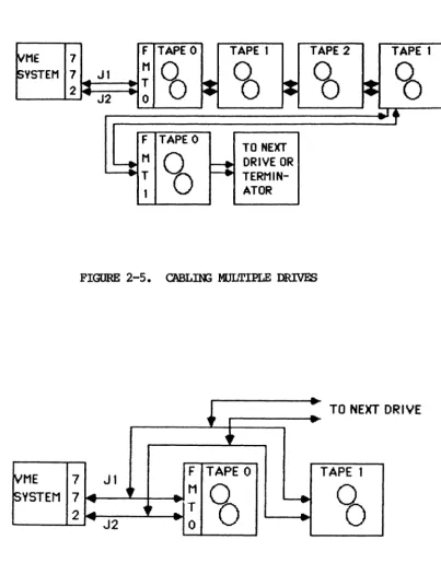
2.10 CABLIN; MULTIPLE DRIVES
Connect the first drive in the chain directly to the 772; connect additional drives together, starting with the first drive. For example, the 772 connects to Drive 0; Drive 0 to Drive 1; Drive 1 to Drive 2, etc. (See Figure 2-5). Be sure to maintain continuity of pin land Jl/J2 connectors between drives.
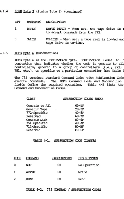
sane
drives have extra connectors on the I/O card for daisy-chaining cables. For drives that do not have extra connections, you must construct a cable with a third connector (See Figure 2-6).mroICS 772 Tape controller User I s Manual
2.10.1 unit
Select
If you are daisy-chaining drives, assign each drive a unique Unit Select number. 'lhe 772 accesses drives with unit numbers fran 0 through 3, and formatter addresses fran 0 through 1.
~ME 7 F TAPE 0 TAPE 1 TAPE 2 TAPE 1
~YSTEM 7 ... Jl M
CO
CO
CO
'6
2 ~ J2
T
~
~
~
..
0~Tf
F TAPE 0
TO NEXT
~ M
~
F:
DRIVE OR..
TTERMIN-1 ATOR
FIGURE 2-5. C'ABLnG ltIlLTIPLE DRIVES
~I
... TO NEXT-.. DRIVE
•
~ME 7 Jl F TAPE 0 TAPE 1
~VSTEM 7 ~ ~t
..
MCO
~CO
...
1t
... T2
~
J2..
...
0--
-FIGURE 2-6. D.JUSY-rnAIN CABLE
[image:27.617.127.530.179.705.2] [image:27.617.130.533.210.369.2]XYIOOIQ; 772 Tape Controller User' s Manual
SECrIOO 3: '!BE 772 REX;ISTERS
3.0 GENERAL
The 772 programming interface is based on the use of seven, one-pyte long, I/O registers. The base address of the register set is defined by the bus address jumpers. Table 3-1 lists the registers along with the base offset fran Which they can be
addressed. The 772 responds to l6-bit words, but only 8 bits are valid.
'!he registers have one function when read, and another when
written. '!he following subsections detail their definitions.
RIDISTER
lOPS ADDRESS BYTE 0 (Least Significant Byte)
10PB ADDRESS BYTE 1 lOPS ADDRESS BYTE 2
lOPS ADDRESS BYTE 3 (Most Significant Byte) lOPS ADDRESS K>DIFIER
a:NlROL AND STA'lUS REGISTER FATAL ERROR REGISTER
TABLE 3-1. REX;ISTER OFFSETS
OFFSET
1
3 5 7
9
B
D
The 772 supports VME short addressing for I/O devices (Al.6) • It responds to Address Modifiers 29H and 2DH. For more information see the VMEbus Specification Manual.
3.1 lOPS ADDRESS REGISTERS
The first four registers define the 32-bit address of an lOPS or lOPS chain. When these registers are written, the 772 interprets it as the address of the lOPS or 10PB chain to be executed. When read, and Remove 10PB (RIO) is set, the registers point to the lOPS or lOPS chain just completed by the 772.
'!be protocol for reading and writing this address register is
defined by the use of the Add lOPS (AIO) and Remove lOPS (RIO) bits in the Control and Status Register (See Section 3.3).
3.2 lOPS ADOOESS K>DIFIER / PRIORITY lOPS RmISTER
rus register defines the Address modifier of the lOPS address.
The VMEbus Specification Manual defines the address modifiers.
XYLOOIC3 772 Tape Controller User's Manual
3.2 IOPB ADDRESS MJDIFIER / PRIORITY IOPB RmISTER (continued)
There is no default value for this register; it must be written each tine the IOPB Address Registers are written. '!his register also specifies whether an IOPB has priority over the current set of IOPBs in the 772 comnand queue. Section 3.3 defines the protocol for reading and writing this register.
PRIORITY IOPB RmISTER
7 6 5 4 3 2 1 0
1
PRIORITY IOPB REQUEST 1 1 1 1
RESERVED 1 1 1 1 I 1
ADDRESS K>DIFIER _ _ _ _ _ _ _ _ _ 1_1_1_1_1_1
lllX MNEMONIC
7 PRIO
6
5-0 AM
DEFINITION
PRIORITY IOPB REXJUEST - When set, the IOPB, or IOPB chain, precedes all others (except the one in process) in the command queue.
RESERVED.
ADDRESS lJDDIFIER - See the VMEbus Specification Manual.
3.3 <XNr.ROL AND STA'IUS REGISTER
When written, this register provides the host with control of the 772 operation; when read, it provides the host with 772 status information. Sections 3.3.1 and 3.3.2 define the bits in this register when read or written.
3.3.1 control Register (Write)
<XNr.ROL RmISTER (WRITE)
7 615 4 3 2 1 0
REGISTER MAINTENANCE IDDE _ _ _
RESERVED _ _ _ _ _ _ _ _ _ _ _ _
ENABLE MAINTENANCE MJDE _ _ _ _ _ _ _ _
RESERVED ____________________ _
CXl\lTROLLER RESET _ _ _ _ _ _ _ _ _ _ _ _ _ _
ADD IOPB _ _ _ _ _ _ _ _ _ _ _ _ _ _ _ _ _ _ _ _ _ _
~ RIO ___________________________ ___
-~-~---~ .. ~-~~-. .
-XYLOOIQ; 772 Tape Controller User I s Manual
3.3.1 Control Register (Write) (continued)
~ MNEMC)lIC
7 RMM
6
5
4
3
2
1
MM
CRST
AIO
CRIO
Rev. A. July 23, 1986
DEFINITION
REGISTER MAINl'ENANCE H)DE - When RMM and MM are set, the values previously written in all the registers (except the Q;R) are echoed back.
RESERVED.
ENABLE MAINl'ENANCE IDDE - Setting MM and AIO places the 772 in Maintenance mode. 'Ibis mode
supports a different Register protocol and is used as a diagnostic tool. Section 8 outlines the l-laintenance Mode.
RESERVED.
CXNrRCLLER RESET - 'Ibis. bit signals the 772 microprocessor to perform a nsoftn reset; it stops the IJIIA, and cancels any IOPBs in the queue. When the Controller Reset cn:npletes, the 772 resets the CSR to zero. A Controller Reset does not initiate a Power-up Self Test.
ADD IOPB - '!be host sets AIO to indicate that the 772 should execute the IOPB (chain) at the address pointed to by the IOPB Address and Address Modifier Registers. Essentially, AIO camnands the 772 to execute a new IOPB or IO:PS chain. As soon as the host asserts this bit, the 772 asserts the AIO Pending (AIOP) bit in the Status Register; this indicates the 772 has
received the AIO signal, but has not yet processed the new chain address. AIOP is negated in the Status Register after the 772 internally stores the
new
chain address. '!be 772 can store up to 50 IOPB Mdresses in this manner. Reasserting AIO if AIOP is asserted in the status Register violates the Register protocol.CLEAR RIO - '!he host sets CRIO to clear the RIO bit in the Status Register. '!YPically, the host sets CRIO after it reads the address of a canpleted IOPB chain from the IOPB Address and Modifier Registers. Clearing RIO enables the 772 to update the lOEB Address and Modifier Registers with the address and Address modifier of a newly canpleted lOEB chain. Clearing RIO if RIO is not asserted in the Status Register violates the Register protocol.
XYLOGICS 772 Tape Controller User's Manual
3.3.1 Control Register (Write) (continued)
3.3.2
RIX MNEMONIC
o
CRBSDEFINITION
a:..EAR RBS - The host sets the Clear Register BUSy (CRBS) bit to clear the RBS bit in the Status Register. Clearing RBS effectively releases the registers for use by another host (See Section 8.2) • (This bit is only relevant in a multiprocessor environment.)
Status Register (Read)
STA'IUS RmISTER (READ)
-7 6 5 I 4 I 3 I 2 I 1 101
BUSY _ _ _ _ _ _ _ _ _ _ _ _
FATAL ERROR _ _ _ _ _ _ _ _ _ _ _ MAINl'ENANCE MJDE ACl'IVE _ _ _ _ _ _ _
RES~ ___________________________ _
OONTROLLER RESET ACl'IVE _______________ _
AIO PENDlt\G _ _ _ _ _ _ _ _ _ _ _ _ _ _ _ _ _
REHJVE IOPB _ _ _ _ _ _ _ _ _ _ _ _ _ _ _ _ _ _ _ _ _ _ RmISTER BUSY SEMAPHORE _ _ _ _ _ _ _ _ _ _ _ _ _ _ _ _
arr
MNEMONIC7 BUSY
DEFINITION
BUSY - '!he 772 is executing IOPBs. The 772 sets BUSY when it clears AIOP to acknCMledge the first IOPB address; it clears BUSY after completing all the IOPBs with no new ones pending (within 500 microseconds of the host clearing RIO on the last
IO:PS). This bit is redefined when the 772 is in Maintenance mode (See Section 8.1).
XYLOOIQ) 772 Tape Controller User's Manual
3.3.2 Status Register (Read) (continued)
.arI f.1NOONIC
6 FERR
5
4
3
2
1
o
MMA
RSl'A
AIOP
RIO
RBS
Rev. A. Julv 23, 1986
DEFINITION
FATAL ERROR - '!he 772 detected a fatal hardware error (a fatal error asserts SYSFAIL). A Controller Reset clears this bit. '!he Fatal Error Register contains more specific information. '!he 772 asserts FERR lll1der the following conditions:
(1) Maintenance Mode Test Failure;
(2) Power-up Self Test Failure;
(3) IOPB Checksum Miscompare;
(4) IOPB Ilo1A Fatal;
(5) lOEB Address Alignment Error;
(6) Firmware Error;
(7) Cable Test Failure;
(8) Illegal Maintenance Mode Test Number; and
(9) ACFAIL Asserted.
MAlNI'ENANCE IDDE ACrIVE - When set, the 772 is in
Maintenance mode (See Section 8) •
RESERVED.
a:Nl'RCLLER RESET ACrIVE - '!he host set the
Controller Reset bit in the Control Register and the 772 is currently resetting.
AIO PENDIK; - When set, the AIO bit has been set in the Control Register, but the 772 has not acknowledged its receipt. When clear, AIO may be set again.
REHJVE lOEB - '!he chain of IOEBs, available in the Modifier Registers.
772 completed an lOEB, or a and has made the address lOEB Address and Address
After the host reads the address and modifier, it must clear the RIO bit
b¥
writing the Clear RIO(CRIO) bit in the Control Register.
REGISTER BUSY SEMAPHORE - RBS provides a means of allowing multiple hosts to share access to the
772 registers wi thout simul taneous access (See Section 8). ('Ibis bit is only relevant in a multiprocessor environment.)
XYLOOIC3 772 Tape Controller User I s Manual
3.4' FATAL ERROR REGISTER
If a fatal error occurs, the 772 returns the appropriate Completion
Code in this register. Table 3-2 lists the fatal error codes; Section 6.4 describes them.
.ewE
EO
El-EF
FO Fl F2 F3 F4 F5 F6
Rev.
A. July 23, 1986DESCRIPl'ION
!RAM. Olecksum Failure Power-up Self Test
lOPS Checksum Miscompare lOPS IJIlA Fatal
lOPS Address Alignment Error Firrrware Error
Gable Test Failure
Illegal Maintenance Mode Test Number ACFAn.. Asserted
TABLE 3-2. FATAL ERROR CDDES
XYLOOICS 772 Tape Controller User I s Manual
SECrlCE 4: lOPS DF.SCRIPrlCE
4.0 GENERAL
'Ibis section describes the 772 rnput/OUtput Parameter Block (IOPB); it begins with the standard roPB for most data transfer oarnmands and follows with variations of the rOPB.
4.1 SI'ANDARD roPB
']he 772 uses the standard roPB for data transfer caranands and sane general purpose commands.
STANDARD 772 IOPB
7 6 5 4 3 2 1 0
0 IERRS I IDONEI ICHENI ISGM
I
I
COMMAND I1 COMPLETION CODE
2
I
HERI
ICER I I RLS I [RLLJI
FMK I I PEID II
EOT] IwPT I 3 I GC/NRI IHISDI
160TI I REWI I DBSV II
FBSV I I DRRDVI (ONLINI
ISU6FUNCTION I
0
I
BHT I 0I
UNITIo
o o
o 04
05
06
07
08
09
OA
08
oc OD
Of
OF
10
11
12
13
14
15
16
17
18
19
I LINK LIST LENGTH I
I
INTERRUPT LEVELI
I
INTERRUPT VECTORI
IREQUESTED COUNT HIGH II REQUESTED COUNT LOW
I
I LAST RECOVERED/IGNORED ERRORS II COUNT OF RECOVERED/IGNORED ERRORS
I
I
ACTUAL COUNT HIGHI
I ACTUAL COUNT LOW I0
I
DATA O~ LINK A[j[ji:!£!;S MODIFIE~II PRIO I
I
0 I NEXT IOP6 ADDRESS MODIFIER II
OAT A OR LINK ADDRESS HIGHI
IDATA OR LINK ADDRESSI
I
OAT A OR LI NK ADDRESS II
DATA OR LINK ADDRESS LOWI
.
INEXT IOP6 ADDRESS HIGHI
I NEXT IOP6 ADDRESS
I
I
NEXT IOP6 ADDRESSI
l
NEXT IOP6 ADDRESS LOWI
l'OP6 CHECKSUM HIGHI
IIOPB CHECKSUM lOW
I
xn..oolCS 772 Tape Controller User I s Manual
4.1.1
.mm
~ Q (Command)----,---7 6 I 5 I 4 I 3 I 2 I 1 101
---,---I
ERROR S(JMl\1ARY
I
OONE
1
ClIAIN ENABLE 1 I 1
SCATI'ER/GA'IHER 1 1 1 1
CXlJ1MAND _ _ _ _ _ _ _ _ _ _ _ _ _
1_1_1_1
~ MNEMONIC PESCRIPI'lON
7 ERRS ERROR SUMMARY - ERRS is only valid if DONE is set. If ERRS is clear, the 772 successfully canpleted the lOPB. If ERRS is set, a hard error occurred during lOPB processing.
6 OONE
5 (lIEN
4
3-0
Clear DONE and ERRS before executing an IOPB.
OONE - When set, the IOPB is complete; if chained, software may remove the IOPB from the chain and reuse it.
ClIAIN ENABLE - When set, the Next IOPB Address Modifier and Next IOPB Address point to the next chained IOPB. When clear, this lOPB is not chained to another IOPB. If OlEN and lEC are set, the 772 returns the whole chain with one RIO; if CHEN is set and IEC is clear, the 772
returns one IOPB at a time.
SCATTER/GA'lHER K)PE - When set, the IOPB is either a scatter (read) or a gather (write) tape
transfer; a linked list describes the number of 16-bit words and to what address the 772 transfers each section of the data. '!he link address modifier and the link address specify the link list location. When clear, this IOPB specifies the data transfer address; the data is transferred to/from contiguous memory. ffiM is only valid for standard reads and writes.
<nftAND - See Table 4-2.
XYI..CX;ICS 772 Tape COntroller User's Manual
4.1.2
4.1.3
.I01'.a ~ ~ (Status Byte 1)
After the 772 executes the lOPS, it sets DONE and posts a Canpletion Code in this byte (the 772 always updates this byte, regardless of AUD's status). Canpletion Codes are only valid if
IXliJE is set. 'Ihe canpletion Code contains the highest error code in the error code hierarchy. For tape related errors, the 772 reports the same status, or a lower error code, in status Bytes 2
and 3. Section 6 details each error code and its recoIIlI1eIlded recovery procedure.
.IOm ~ 2. (Status Byte 2)
IOPB Byte 2 is a Tape Status byte; it is only valid if DONE is set.
7 6 5 4 3 2 1 0
HARD TAPE ERROR _ _ _ _ _ _ OORRECI'ED TAPE ERROR _ _ _ _ _ _ RECDRD LEtU1ll SHORr _ _ _ _ _ _ _ RECDRD LEN;'lH LeN; _ _ _ _ _ _ _ _ _
Fn.E MARK DETEXJrED _ _ _ _ _ _ _ _ _ _ _
PHASE ENaDED ID BURSr _ _ _ _ _ _ _ _ _ _ _ END OF TAPE _ _ _ _ _ _ _ _ _ _ _ _ _ _ _ _ _ _
WRITB-~ _ _ _ _ _ _ _ _ _ _ _ _ _ _ _ _ _ _ ___
.lUl 7
6
5
4
3
2
MmU)NIC
HER
CER
RLS
RLL
FMK
PEID
DESCRIPl'ION
HARD TAPE ERROR - '!he 772 sets HER when a hard tape error occurs.
OORRECI'ED ERROR - 'Ihe 772 sets CER when the tape drive indicates it corrected a media flaw.
RECDRD LEl\G'lH SHORr - 'Ihe 772 sets RLS when it detects a Record Length Short error during a
Read co