Efficient 2D Linear-Phase IIR Filter Design and
Application in Image Filtering
Chi-Un Lei, Chung-Man Cheung, and Ngai Wong
∗Abstract—We present an efficient and novel
proce-dure to design two-dimensional (2D) linear-phase IIR filters with less hardware resource. A 2D linear-phase FIR filter prototype is first designed using semidefi-nite programming (SDP). The prototype filter is then decomposed into modular structures via Schur de-composition method (SDM). Each section is reduced into IIR structures using a novel digital system iden-tification technique called the Discrete-Time Vector Fitting (VFz). Examples with image processing ap-plication show the algorithm exhibits fast convergence and produces low hardware cost and accurate filters.
Keywords: 2D IIR filter, image processing, digital sys-tem identification, vector fitting
1
Introduction
Two-dimensional (2D) filters are widely used in image processing [1], medical imaging [2], face recognition [3] etc. These applications often require high-order filters having accurate magnitude response and linear phase in the passband. For instance, a 63 pixel ×63 pixel kernel filter is used in medical imaging [2]. However, hardware resources are usually restricted due to limited multipli-ers and memory in ASICs and FPGAs [4]. Therefore, 2D IIR filters are generally used to reduce the hardware cost. However, to date there is no optimal algorithm for 2D IIR filter design in terms of computation and the resultant hardware cost. Direct optimization of an IIR filter gives an excellent accuracy but the computation complexity is high [5]. In the Singular Value Decomposition (SVD) approach, the frequency response of a 2D FIR prototype filter is replaced with parallel sections of 1D cascaded sub-filters [6]. The problem is then reduced from a 2D design problem into several 1D design tasks, thus producing less complicated implementation due to parallelization and modularization of filter sections [7]. By neglecting sec-tions associated with small singular values, the decom-posed filter can be simplified with only slight error in the filter response [6]. Moreover, subfilters can be reduced by IIR approximation using model order reduction method to further reduce hardware cost. However, this method is complicated when the subfilter sizes and number of
sec-∗The authors are with the Department of Electrical and Elec-tronic Engineering, The University of Hong Kong. Phone: ++852 +2859 1914 Fax: ++852 +2559 8738 Email: {culei, edmondche-ung, nwong}@eee.hku.hk
tions are large. To this end, we present a novel design flow for designing 2D (near-)linear-phase IIR filters with low computational complexity and hardware cost. First, semidefinite programming (SDP) is used to design a 2D FIR filter prototype, followed by the Schur Decomposi-tion Method (SDM) that decomposes the prototype filter into sections of cascaded 1D FIR subfilters. A novel dig-ital system identification technique, called the Discrete-Time Vector Fitting (VFz), is then used to reduce the 1D FIR subfilters into 1D IIR subfilters. It is shown that VFz gives efficient and accurate IIR approximation over con-ventional schemes. Practical image processing example demonstrates that the integrated SDP/SDM/VFz design flow produces excellent 2D IIR approximants with good passband phase linearity and low hardware cost.
2
Design Methodology
2.1
FIR prototype design via semidefinite
programming
The transfer function of a 2D FIR filter of odd order (N1,
N2) is characterized by
H(z1, z2) =
N1−1
X
i=0
N2−1
X
j=0
hijz
−i
1 z
−j
2 =z
T
1Hzˆ 2, (1)
wherezi=
h
1 z−1
i . . . z
−(Ni−1)
i
iT
for i = 1 and 2,
and ˆH ∈RN1×N2 is impulse response. This kind of
fil-ter with phase linearity becomes octagonal-symmetric [7]. Therefore, ˆH can be partitioned as:
ˆ
H =
H11 h12 H13
hT
21 h22 hT23
H31 h32 H33
, (2)
where H11, H13, H31, H33 ∈ Rn1×n2, h12, h32 ∈
Rn1×1
, h21, h23 ∈ Rn2×1, h22 ∈ R and n1 =
(N1−1)/2, n2 = (N2−1)/2. Moreover, the frequency
response is given by
H(ω1, ω2) =e−j(n1ω1+n2ω2)cT1 (ω1)Hc2(ω2) (3)
where ci(ωi) = [ 1 cosωi . . . cosniωi ]T, for i = 1
and 2, andH =
h22 2hT23
2h32 4H33
The design of the prototype FIR filter is a minimax prob-lem of error of H in (ω1, ω2) [5]. It can be formulated as
min cTx
subject to : F(x)≥0 (4)
where c = 1 0 . . . 0 T, and
x = δ hT T, in which F(x) =
diagnΓω1(1), ω(2)2 , . . . ,Γω1(M), ω2(M)o ≥ 0. Here
≥ denotes matrix positive semidefiniteness. Adw
is the weighted desired magnitude response. h and cω are column vectors by stacking from the
first to last columns of H and ckn1+m, respectively.
ckn1+m(ω1, ω2) = cos(mω1) cos(kω2) for 0 ≤ m ≤ n1,
and 0 ≤ k ≤ n2. This is a semidefinite programming
(SDP) problem. SDP is an optimization framework wherein a linear or convex objective function is mini-mized subject to linear matrix inequality (LMI)-type constraints.
2.2
Schur decomposition of 2D FIR filters
The octagonal-symmetric linear phase 2D FIR filters can be decomposed into 1D subfilters by Schur Decomposi-tion Method (SDM) [7]. SDM is superior to SVD in com-putational complexity by exploitation of filter response symmetry. The idea of SDM is to decompose the 2D transfer function as:
H(z1, z2) =
k
X
l=1
Fl(z1)Gl(z2), (5)
where Fl(z1) =
NP1−1
i=0
fl(i)z1−i and Gl(z2) =
NP2−1
j=0
gl(j)z
−j
2 are the transfer functions of two cascaded
1D subfilters, fl(i) andgl(j) are the corresponding
im-pulse responses, and k is the number of parallel sections. k is chosen regarding the tradeoff between computation and approximation accuracy. With the octagonal sym-metry, ˆH in (2) can be rewritten as
ˆ
H =
IL 0
b
I IM
H1 0
0 0
IL IbT
0 IM
=
"
H1 H1IbT
b
IH1 IHb 1IT
# (6)
where ˆI=
0 · · · 0 1 0 0 · · · 1 0 0 ..
. . .. ... ... 1 0 · · · 0 0
andL=ni+ 1. H1∈
RL×L contains all the impulse response information of
the 2D FIR filter [7]. H1 is then decomposed by means
of SDM:
UTH1U =
X
, (7)
F1(z1)
F2(z1)
Fk(z1) s1
s2
sk
F1(z2)
F2(z2)
Fk(z2)
+
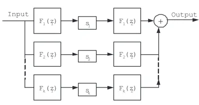
[image:2.595.327.526.65.170.2]Input Output
Figure 1: Decomposed FIR prototype filter.
where UTU =U UT =I
L and P=diag(λ1, λ2, ..., λL).
Retaining the k most significant eigenvalues in P , namely, P1 = P(1 : k,1 : k), the approximated 2D FIR filter becomes
˜
Hd=W|Σ1|SWT =F SG=F SFT, (8)
where W =
U(:,1 :k)
ˆ
IU(:,1 :k)
, F = Wp|P1| ∈ RN×k ,
G = FT , and S = diag(s
1, s2, ..., sk) , in which sl =
sign λ¯l
, is the sign weight for interconnection between subfilters. Each column of F is an FIR linear phase 1D subfilter with its own frequency response. Therefore, (8) becomes
˜
Hd=
k
X
l=1
FlslFlT, (9)
˜
Hd preserves phase linearity of the 2D FIR filter. The
architecture of the decomposed filter is shown in Fig. 1.
2.3
IIR filter approximation of 1D FIR
sub-filters
For the sake of hardware savings and consequently power consumption, each of the 1D FIR subfilters (F1, F2,. . .,
Fk) is approximated by IIR structures:
L
X
n=0
hnz
−n=F
l(z)≈fb(z) =
P(z)
Q(z) =
N
P
n=0
pnz−n
M
P
m=0
qmz−m
.
(10)
where fb(z) is the IIR approximant. We aim at locating a set of pn and qm with N, M≪ L to form a stable and
causal IIR filter with a good approximation subject to constraints like magnitude and phase response, and low algorithmic complexity.
3
Discrete-Time Vector Fitting
desired response f(s). The poles on both sides of the equality are set to be equal:
N
X
n=1
cn
s−αn
!
+d+se
| {z }
(σf)(s)
≈
N
X
n=1
γn
s−αn
!
+ 1
!
| {z }
σ(s)
f(s).
(11)
The basis of partial function ensures well-conditioned arithmetic. The poles (αn) and residues (γn) are either
real or exist in complex conjugate pairs. The variables
cn,d,e, andγnare solved by evaluating (11) at multiple
frequency points. In (11), the set of poles of (σf) (s) and
σ(s)f(s) are the same. Therefore, the original poles of f(s) cancel the zeros of σ(s), which are assigned as the next set of known poles to (11). This iteration process continues until the poles are refined to the exact system poles. In general, it only takes a few iterations. VF is readily applicable to digital domain (z-domain), called Discrete-Time Vector Fitting (VFz), for IIR approxima-tion of FIR filters [9]. In the VFz approach, an initial set of stable poles nα(0)n
o
is first assigned to be refined. Analogous to VF, the desired 1D FIR filter response is fitted with a rational function:
N
X
n=1
cn
z−1−α(ni)
!
+d
| {z }
(σf)(z)
≈
N
X
n=1
γn
z−1−α(ni)
!
+ 1
!
| {z }
σ(z)
f(z).
(12)
In digital systems, it is required that|αn|>1 since stable
poles are inside the unit circle. For Nsfrequency points
at z = zm (m= 1,2, . . . Ns) and Ns ≫ 2N + 1, (12) is
presented in an overdetermined linear equation
N
X
n=1
cn
z−1
m −α( i)
n
!
+d−
N
X
n=1
γnf(zm)
z−1
m −α( i)
n
!
≈f(zm),
(13)
wherei is the ith iteration. It can be solved by
Ax=b, (14)
where the mth row in A, Am, and entries in
the column vector b, bm, and x are Am =
h 1
zm−1−α(1i) . . .
1
zm−1−α(Ni)
1 −f(zm)
zm−1−α(1i) . . .
−f(zm)
z−m1−α(Ni)
i
,
x = c1 . . . cN d γ1 . . . γN
T
, and
bm=f(zm).
To determine the new poles (the reciprocals of zeros of
σ(s)) for next iteration, the poles are computed by the eigenvalues of the following function:
Ψ =
α(1i)
α(2i)
. ..
α(Ni)
− 1 1 .. . 1
γ1 . . . γN
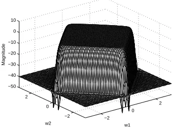
[image:3.595.335.510.85.215.2](15) −2 0 2 −2 0 2 −50 −40 −30 −20 −10 0 10 w1 w2 Magnitude
Figure 2: Magnitude response of the 2D prototype low-pass FIR filter by SDP.
To ensure stability,α(ni+1)
must be greater than 1. Un-stable poles are relocated by flipping their reciprocals, 1/α(ni+1), into the unit circle. This is possibly done
by multiplying both sides of (12) by an allpass filter
z−1−α(i+1)
n
1−α(ni+1)z−1. Here only the phase is changed. When all
the poles converge, σ(z)≈1. It turns out that the IIR denominator part is determined by
˜
f(zm) =
N
X
n=1
cn
z−1
m −α( NT)
n
!
+d≈f(zm). (16)
VFz is also extended to handle complex conjugate poles commonly found in digital filters. The accuracy and com-putational complexity of VFz are dependent of the or-der of the 1D subfilters, the number of iterations and frequency-sampling points. In short, VFz improves the approximation accuracy successively by using determinis-tic pole relocation techniques. It is shown by experiments that its accuracy is comparable, if not better, than that of model reduction techniques [10,11], but with much less computational complexity. The saving is even more sig-nificant when the number of subfilter sections is large. This result is remarkable. Besides magnitude approxi-mation, VFz simultaneously performs accurate phase ap-proximation, whose linearity is particularly important in image processing.
4
Numerical Example
We would like to verify the performance using two nu-merical examples. The proposed design methodology is illustrated with a practical lowpass filter example similar to that in [5]. A diamond-shape linear-phase FIR filter with order = (37, 37) is used whose specification is
W(ω1, ω2) =
0dB, for|ω1|+|ω2| ≤0.8π
−40dB, for|ω1|+|ω2|> π
−2 0
2
−2 0 2 −50 −40 −30 −20 −10 0 10
w1 w2
[image:4.595.338.512.79.220.2]Magnitude (dB)
Figure 3: Magnitude response of the approximated 2D lowpass FIR filter after SDM.
−2 0
2
−2 0 2 −40 −20 0
w1 (a)
w2
Magnitude (dB)
−2
0 2
−2 0 2 0 10 20 30
w1 (b)
w2
Group Delay
Figure 4: Frequency response of the approximated 2D lowpass IIR filter via VFz: (a) magnitude response and (b) group delay in the passband.
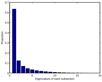
0 5 10 15 20
0 0.1 0.2 0.3 0.4 0.5 0.6 0.7
Proportion
Eigenvalues of each subsection
Figure 5: Eigenvalues of the lowpass filter example H1
of (7) in ratio, which shows the importance of each sub-section.
[image:4.595.78.253.126.267.2]Uniformly distributed grid points of 47 × 47 are used. The algorithm is coded in Matlab m-script file and run under Matlab 7.2 environment on a 1G RAM 3.4GHz computer. The filter specification is first converted into an SDP problem containing 5651 equations. The pro-totype filter is decomposed into five sections (k = 5) by SDM, which is the most important subsection (sec-tions with the five largest eigenvalues proportion, shown in Fig. 5). Figs. 2 and 3 show the magnitude response of filter after using SDP and SDM, respectively. Each section is then approximated by a 1D IIR subfilter us-ing VFz with orders 19, 20, 19, 20, and 21, respectively. The numerator and denominator in each 1D filter are of the same order. 130 sampling points and 5 iterations are used in VFz. Fig. 4 shows the frequency response of the final 2D IIR filter. The normalized rms errors of the IIR filter approximant are 0.4% and 0.6% in the passband and stopband, respectively. The normalized rms errors between the final design and the ideal design are 4% and 5%, respectively. Furthermore, as seen in the figure, the IIR filter approximant preserves linearity (constant group delay) in the passband and the approximation error is mainly introduced in SDM. The computation time is 507 CPU seconds for FIR prototype filter design (using SDP) and only 1.51 CPU seconds for IIR approximation (using Schur decomposition and VFz approximation). Its ad-vantage in fast computation is therefore demonstrated. Fig. 7 shows that VFz can achieve good approximations for subfilter design. The normalized errors of subfilter approximations are 0.1%, 0.1%, 4%, 4%, and 5%, respec-tively. Compared to a direct implementation of the orig-inal 2D FIR filter, the proposed SDP/SDM/VFz design flow has resulted in a hardware saving (essentially mul-tipliers) of more than 50%. Fig. 8 shows an image noise filtering example.
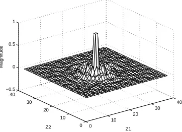
[image:4.595.77.251.423.642.2]0 10
20 30 40
0 10 20 30 40 −0.3 −0.2 −0.1 0 0.1 0.2 0.3 0.4 0.5
Z1 Z2
[image:5.595.78.258.142.272.2]Magnitude
Figure 6: Impulse response of the approximated 2D IIR lowpass filter via VFz.
0 0.5 1
−60 −40 −20 0 20
Normalized Frequency
dB
(a)
0 0.5 1
−60 −40 −20 0
Normalized Frequency
dB
(b)
0 0.5 1
−60 −40 −20 0
Normalized Frequency
dB
(c)
0 0.5 1
−60 −40 −20 0
Normalized Frequency
dB
(d)
0 0.5 1
−100 −50 0
Normalized Frequency
dB
(e)
Actual Approx.
Figure 7: Magnitude response of subfilter approximation using VFz. (a) - (e) are subfilters of sections 1-5 respec-tively.
(a)
[image:5.595.357.505.199.556.2](b)
[image:5.595.78.251.446.638.2]frequency. A circular-shape linear-phase FIR filter with order = (37, 37) is used whose specification is
W(ω1, ω2) =
0dB,
0dB,
−40dB,
for 0<pω2
1+ω22≤0.5π
for 0.8π <pω2
1+ω22≤π
for 0.6π <pω2
1+ω22<0.7π.
(18)
Uniformly distributed 47×47 grid points are used. The prototype filter is decomposed into four sections (k = 4) by SDM. Fig. 11 shows the proportion of the eigenvalues. The figure shows that the first few sections have the large rest eigenvalues and contribute most proportion of filter characteristic. Each section is then approximated by a 1D IIR subfilter using VFz with orders 18, 19, 20, and 21, respectively. The numerator and denominator in each 1D filter are of the same order. 100 sampling points and 7 iterations are used in VFz. Figs. 9 and 10 show the fre-quency response and impulse response of the final 2D IIR filter respectively . As seen in the figure, the IIR filter ap-proximant preserves linearity (therefore, constant group delay) in the passband. Two figures of noise removal are shown in Fig. 12(b) and Fig. 12(c) using 2D FIR pro-totype filter and 2D IIR filter, respectively. They both show that noise is greatly reduced without much blurring to the original image. The degradation in image quality is small when the 2D FIR prototype filter is replaced with the 2D IIR filter.
The computation time is 528 CPU seconds for FIR pro-totype filter design (using SDP) and 1.2987 CPU sec-onds for IIR approximation (using Schur decomposition and VFz approximation). Its advantage in fast 2D IIR approximation is therefore demonstrated. The num-ber of multipliers in the 2D IIR filter is 156, which saves 45.5% multipliers of the original symmetric filter (37×37÷4 = 343). Consequently, it is demonstrated that the proposed IIR filter design flow reduces hard-ware cost while preserving similar filtering quality when compared to a direct implementation of the original 2D FIR filter.
5
Remarks
1. Besides using SDP, other common and faster de-sign techniques such as the windowing method can be used to design the 2D FIR filter prototype. The SDM/VFz post-processing can then be used to achieve even faster IIR approximation.
2. The most direct approach is to direct decompose the desired frequency response into sections using frequency SVD and then realized each sections by VFz. This can avoid introduced error and relatively time consumed in the 2D FIR prototype filter de-sign. This modification can generate a 2D IIR filter within a few seconds.
−2 0
2
−2 0 2 −40 −20 0
w1 (a)
w2
Magnitude (dB)
−2 0
2
−2 0 2 −10
−5 0 5 10
w1 (b)
w2
[image:6.595.335.511.125.359.2]Group Delay
Figure 9: Frequency response of the 2D bandstop IIR filter via the proposed algorithm: (a) magnitude response and (b) group delay in the passband.
0 10
20 30
40
0 10 20 30 40 −0.5 0 0.5 1
Z1 Z2
Magnitude
[image:6.595.336.517.537.668.2]0 5 10 15 20 0
0.1 0.2 0.3 0.4 0.5 0.6 0.7 0.8
Proportion
[image:7.595.82.254.80.220.2]Eigenvalues of each subsection
Figure 11: Eigenvalues of the bandstop filter exampleH1
of (7) in ratio, which shows the importance of each sub-section.
3. In addition to reducing multipliers, the proposed fil-ter structure is also favorable for VLSI implemen-tation. The identical subfilters exhibit regular and modular structures, which lead to reduction in inter-connect area and simple floor-planning and layout. Multiplierless filter design techniques are also avail-able for further reducing the hardware cost within the IIR filter structures [12].
4. This paper has extended the Vector Fitting concept to the 2D discrete-time domain. The idea can be further generalized to n-D IIR filter design, which is useful in video processing and medical imaging.
5. Besides the bandreject filter in our example, the pro-posed algorithm is also applicable to the efficient construction of 2D lowpass, highpass and bandpass filters, with possible applications in image noise re-moval and edge detection etc.
6. The relationship among error and number of sections and filter orders is still investigated. The investiga-tion objective is to fully integrate Schur decomposi-tion and VFz such that filter can be designed within a controlled error and the lowest hardware cost. As the frequency response in later order is irregular, it is not optimal to use lower order subfilters for later subsections.
7. VFz can be generalized as a frequency masking filter design technique. It is similar as WLS method [13] with novel weighting construction to simplify calcu-lation. Furthermore, VFz can limit the maximum pole radius, which can control the sensitivity of the quantization error.
6
Conclusion
A new 2D IIR filter design flow has been proposed which utilizes the SDP/SDM/VFz integration to efficiently ob-tain accurate IIR approximants from 2D linear-phase FIR
(a)
(b)
[image:7.595.359.498.89.637.2](c)
filter prototypes. Hardware cost is significantly reduced due to parallel and modular 1D IIR subfilters. Image pro-cessing examples have demonstrated that the proposed approach renders high approximation accuracy, low hard-ware cost, and low computational complexity, and effec-tively preserves passband phase linearity.
Acknowledgment
This work was supported in part by the Hong Kong Re-search Grants Council and the University ReRe-search Com-mittee of The University of Hong Kong.
References
[1] R. Gonzalex and R. Woods,Digital Image Process-ing, 2nd ed. Upper Saddle River, N.J.: Prentice-Hall, 2001.
[2] R. Kreuger, “Virtex-EM FIR filter for video applications.” [Online]. Available: http://direct.xilinx.com/bvdocs/appnotes/xapp241.pdf
[3] S. M. S. Gong and A. Psarrou, Dynamic Vision: From Images to Face Recognition, 1st ed. Impe-rial College Press, 2000.
[4] P. C. C. Bouganis, G. Constantinides, “A novel 2D filter design methodology for heterogeneous de-vices,” inIEEE FCCM05, 2005, pp. 13–22.
[5] W. Lu, “A unified approach for the design of 2D digital filters via semidefinite programming,” IEEE Trans. Circuits Syst. I, vol. 49, no. 6, pp. 814–826, June 2002.
[6] M. A. W.P. Zhu and M. Swamy, “Realization of 2-D linear-phase FIR filters by using the singular-value decomposition,” IEEE Trans. Signal Process-ing, vol. 47, no. 5, pp. 1349–1358, Mar. 1999.
[7] R. Aldhaheri, “Design of 2-D linear phase digital filters using schur decomposition and symmetries,” vol. 15, no. 1, pp. 65–81.
[8] B. Gustavsen and A. Semlyen, “Rational approxi-mation of frequency domain responses by vector fit-ting,” IEEE Trans. Power Delivery, vol. 14, no. 3, pp. 1052–1061, July 1999.
[9] N. Wong and C. Lei, “FIR filter approximation by IIR filters based on discrete-time vector fitting,” in
Proc. IEEE Symp. Circuits and Systems, May 2007, to appear.
[10] B. Beliczynski, I. Kale, and G. D. Cain, “Approx-imation of FIR by IIR digital filters: an algorithm based on balanced model reduction,” IEEE Trans. Signal Processing, vol. 40, no. 3, pp. 532–542, Mar. 1992.
[11] H. K. Kwan and A. Jiang, “Recent advances in FIR approximation by IIR digital filters,” in Proc. Int. Conf. Communications, Circuits and Systems, June 2006, pp. 185–190.
[12] C. Lei and N. Wong, “Multiplierless polynomial-operator-based IIR filters for efficient VLSI imple-mentation,” inIEEE TENCON, 2006.