The Area and Wire Length Interconnection for
VLSI Floor Planning Problem by using
Optimization Techniques
G. Sujatha1, Dr. N. Balaji2
1
Assistant Professor, Department of Electronics and Communication Engineering, Sree Rama Engineering College, Tirupati, A.P., India
2
Professor, Department of Electronics and Communication Engineering, JNT University, Kakinada, A.P. India
Abstract: The present research work, a new Area and Wire Length Interconnection for VLSI Floor Planning Problem by using optimization Techniques is presented. The floor planning affords early response that evaluates architectural choices, approximation of chip space, estimates delay, interconnect length and congestion caused by wiring. As technology advances, style complexness is immensely increasing and therefore the circuit size is obtaining larger. Thus, the space of the circuit gets increased and becomes tougher to minimize the interconnect length. The VLSI is a necessary design step in the estimation of the chip area before the optimized placement of digital blocks and their interconnections. Since VLSI floor planning is an NP-hard problem, several improvement techniques were adopted to find optimal solution. The present research work using tends to take into account, a multi-objective hybrid optimization techniques in Fire-fly optimization (FA) algorithm is employed for the fixed die outline constrained floor planning, with the ultimate aim of reducing the full chip area. The PSO with Biogeography fire-fly algorithm approach is employed for minimizing the whole space and interconnects length. The experimental results to achieve global solution for fixed outline constraints and for this we tend to taken MCNC and GSRC benchmark circuits
Keywords: Biogeography fire-fly Algorithm, slicing floor planning, VLSI, MCNC, GSRC
I. INTRODUCTION
The VLSI cell placement problem is known to be NP-hard [1]. The input to the placement problem is a set of modules with fixed shapes and fixed terminal positions and net list representing connecting information among modules. The placement typically aims at finding the best locations for each module throughout the placement region while optimizing the appropriate objective functions. There are two approaches: constructive placement and iterative improvement placement. A subset of modules has typically pre-assigned positions.
Over the last decade, several meta-heuristic algorithms are proposed for solving hard and complex optimization problems. The effectiveness of this algorithm gives satisfaction in solving the most difficult problems for many algorithms related to various optimization problems. The proposed architecture is tested on some benchmarks functions. We have also analyzed the operators of GAs to describe how the performance of each one can be enhanced by incorporating some features of the other. We used standard benchmarks functions for making comparison between the two algorithms. In fact, PSO algorithm uses the technique [2] that explores all the search space to fix parameters which minimize or maximize a problem. So, the ability and the simplicity of solving the complex problems make the studies active in this area compared with many others optimization techniques [3] [4].
II. REVIEW OF RECENT RESEARCHES
Floor planning is the first stage of the very large scale integrated circuit (VLSI) physical design technique. In this the resultant quality of this stage is very important for successive design stages. If we see this from the computational point of view, VLSI floor-planning is an NP-hard problem. In this paper, a genetic algorithm (GA) for a non-slicing and hard-module VLSI floor-floor-planning problem is presented. The GA uses an effective genetic search method for exploring the search space and an efficient local search method to exploit information in the search domain. Experimental results on MCNC benchmarks show that the GA is very effective and promising in building block layout application [6]. This paper employed Firefly Algorithm (FA) in order to solve this complex combinatorial problem. The FA introduced by Xin-She Yang [7-8] in 2007 is inspired by the mating behavior of the fireflies. During matting season, fireflies flash light from their bodies to attract potential mating partners and firefly with relatively higher light intensity will attract other fireflies to move towards it. This matting behaviour is translated into optimization algorithm where the firefly represented as agent that suggested a potential solution of the problem. The light intensity of the firefly represent the fitness of the solution proposed by the potential solution, whereas the movement of the fireflies towards other fireflies with better light intensity represents the improvement mechanism of the agents, in order to find better solution of the problem. The modeling of the problem and application of FA algorithm are described. Case study taken from is used to benchmark the performance of the proposed approach.
Research related to exploiting the features of the PSO and Firefly algorithm for floorplanning to optimize area and wirelength is rarely found in the literature. Hybridizing the PSO and FA will result in faster convergence and avoid getting stuck into local minima. The efficiency of the floorplanning can be enhanced by dealing with soft Intellectual Property (IP) modules placement instead of hard modules. Hence, a new methodology which integrates MCL algorithm for floorplan representation which has minimal computational complexity with larger search space, PSO and Firefly algorithm for their best global and local search mechanism respectively for soft modules is proposed in this paper.
III. PROBLEM DEFINITION
The floor planning problem consists of a set of modules on an integral circuit to be arranged on a planar area in such a way that they will not overlap each other while the occupied areas’ measurements, which are given by their formulas, are to be optimized. Solve the problem where the total space unoccupied by the modules is minimized with a non-overlapping constraint by an experimental algorithm. The minimization function is given as a ratio.
The floor planning problem comprises a set of modules on an integral circuit to be arranged on a planar area in such a way that they will not overlap each other while the occupied areas’ measurements. The non-slicing floor plan represents PSO and Firefly algorithm to obtain the near optimal solution. With the application of PSO-GA algorithm with B*-tree, the following limitations are observed: transformation of B*-tree to floor plan representation results in a different solution and it may change after placement, difficult in constructing a B*-tree for a non-compacted floor plan, and incomplete adjacency information.
IV. PROPOSED METHOD
A. Slicing floor plan
A slicing floor plan is obtained by cutting the floor plan either horizontally or vertically repetitively. Fig.1 (a) represents slicing floor plan. A slicing tree could be a binary tree. The pre-placed module could be a one during which modules coordinates’ area unit given by the floor planner. Let H denotes set of hard modules, S denotes set of soft modules and P denotes set of preplaced modules. Let M be the union of those three sets of modules. The illustration of floor planning will be exhausted two layout forms, specifically the slicing structure and non-slicing that is used to represent a slicing floor plan. Generally, there are two cut sorts, + and -. The + and - represent floor plan horizontal (vertical) cut. Fig.1 (b) shows a slicing tree
B. Non slicing floor plan
Non- slicing floor plan is more common than slicing floor plan. All the children of the given cell cannot be obtained by bisecting the floor plan. This is called non-slicing floor plan. Horizontal constraint graph and vertical constraint graph can be used to model a non-slicing floor plan. In a constraint graph, a node represents a module. The foremost aim of this paper is to minimize the dead space (white space) and fix the module in fixed outline constraint. In this paper we dealt with slicing floor planning
Fig 2 (a). Non slicing Fig 2(b). Floor plan Vertical and Horizontal Constraint
C. Particle Swarm Optimization
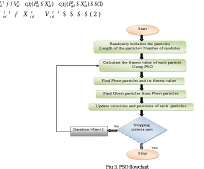
PSO is a population based bio-inspired algorithm. Initially, population of candidate solutions is defined. Each solution in the population represents a particle. The fitness value is calculated for individual particles. Flowchart of the proposed PSO algorithm is shown in Fig. 3. The position of each particle is updated by using a velocity term that is defined by the Equations (1) and (2).
1
1 1( ) 2 2( ) (1)
t t t t t t id id id id gd id
V V c r P X c r P X
1 1
( 2 )
t t t
i d i d i d
[image:3.612.120.487.147.265.2]X
X
V
Fig 3. PSO flowchart
[image:3.612.54.462.337.675.2]D. Firefly algorithm
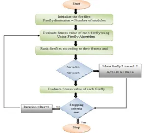
Firefly algorithm is a nature-inspired meta-heuristic algorithm which utilizes firefly’s capacity of emitting short and rhythmic flashes with a particular intensity. This light acts as a source of attraction and communication between two fireflies. But, the intensity of the firefly decreases with the increase in the travelling distance of the light and is limited to a narrow region
The strength of attraction depends upon the intensity of the brighter firefly and the distance between the two fireflies. Since floor plan problem is related to minimization of the objective function, the functionality of the brighter intensity fly in the above stated phenomena can be replaced by lower intensity firefly and vice-versa. Detailed flowchart of the proposed Firefly algorithm is shown in Fig. 4.
The attractiveness between two fireflies is given by Equation (3).
2
0
(3)
r
e
Where, r is the distance between the two fireflies, β0 is the attractiveness between the two fireflies at r = 0 and γ is the light absorption coefficient.
Let xi be the higher intensity firefly and xj be the lower intensity firefly, then xi moves towards xj by using Equation (4)
1
(
)
(4)
t t t t
i i j i
x
x
x
x
Where, α stands for the random parameter between 0 and 1 while ∈ represents the random number from Gaussian distribution.When
γ= 0, attractiveness is β =β0and constant throughout the search space. If γ= α, the second term is removed from Equation 3 and firefly performs a random walk. To find a better solution, the parameters are analyzed empirically and the resulting parameter settings are listed in Table Flashing light of the firefly is encoded as the fitness function to be optimized and each firefly represents a solution in the search space with the following three rules:
1) A firefly would be attracted by other fireflies because of their sex.
2) The attractiveness of the firefly depends on their brightness and it gets reduced if the distance between them increases. If two blinking fireflies are available, then one which has less brightness would move towards the brighter firefly, in a particular region if there is no brighter firefly, then fireflies in that region move in a random fashion.
3) Brightness of a firefly is encoded as the objective function of optimization problem.
[image:4.612.164.446.458.719.2]Two important issues in Firefly algorithm are aviations of the light intensity and formulation of attractiveness. These two factors depend upon the intensities of the two fireflies as well as the distance at which they are separated from each other.
A. PSO-Firefly Algorithm
The process of hybridizing PSO and Firefly algorithms to optimize the floor plan fitness function is presented in the following steps:
1) Step1: Load the input benchmark file and the parameters of PSO algorithm are initialized.
2) Step2: Generate initial population of particles with particle length equal to the number of modules to be optimized and initialize its positions and velocity.
3) Step3: Calculate the fitness value of each particle using MCL placement strategy. Based on the minimum fitness values, the corresponding particles are assigned with the positions of personal best (Pbest) at initial iteration. Let the initial global best (Gbest) be the lowest Pbest value.
4) Step4: Update the velocity and position of the particles
5) Step5: Check the fitness value of every particle in succeeding iterations. If it is better than its corresponding Pbest, then update its Pbest value.
6) Step6: Update Gbest for every iteration. If the Gbest obtained is smaller than the previous Gbest, then update newer one as the final Gbest.
7) Step7: Repeat step 3 to step 6 till the termination condition is reached. The termination condition may be the end of the number of iterations or the repetitive occurrence of the same output for the number of iterations defined by the user.
8) Step8: If the termination condition is satisfied, then pass the present Pbest particles as the input to initial fireflies of the Firefly algorithm.
9) Step9: Initialize the Pbest particles obtained from the PSO as the initial fireflies of the Firefly algorithm.
10) Step10: Evaluate the fitness values of the fireflies and rank them based on the values. Assign the current best to the firefly with minimum fitness value.
11) Step11: Compare all the fireflies individually with each other and move the higher intensity firefly towards lower intensity firefly using Equation (4).
12) Step12: Repeat step 9 to step 10 till the termination condition is reached.
B. Fitness evaluation
In PSO-FA based hybrid algorithm, each particle and firefly corresponds to a potential solution. Therefore, a layout can be obtained after decoding the particles and fireflies. Normally, the objective function is to minimize the chip area and wire length of floor planning. Considering the minimization of area, the fitness is equal to the value of the area. Thus the fitness function for the area of the floor plan p(x) can be represented in Equation (5).
( )
( )
( )
(5)
P x
W x xH x
Where, W(x) is the width of the corresponding floor plan x and H(x) is the height of the floor plan x. The wire length of the Pth module with respect to the other modules in the given floor plan can be calculated by using Half-Perimeter Wire length (HPWL), defined as half the perimeter length of the
smallest bounding box that encloses all pins. HPWL of the net ‘i’ is calculated using Equation (6).
max min max min
(
)
(
)
(6)
p
L
X
X
Y
Y
Where, Xmax and Xmin are the maximum and minimum x-coordinates of the HPWL bounding box of the net. Similarly, Ymax and Ymin are the maximum and minimum y-coordinates of the HPWL bounding box of the net. The total wirelength for ‘m’ nets is calculated using Equation (7).
1
( ) ( 7 )
m
p p
q x L
For multi-objective optimization, a weighted sum method is proposed to handle multiple objectives simultaneously. Each objective in the fitness function is measured in different units (area-mm2 & wire length-mm and run time-sec) and so, to obtain a linear objective function, every term in the fitness function is normalized. The normalized fitness function is calculated using Equation (8).
( ) * ( ) * ( ) ( 8 )
y x P x Q x
Where
1 ( )
( ) ( 8 )
( )
N
i i
p x b
P x a
p x ( )
( ) * q x ( 8 )
Q x b
n o r m
Where, α and β are constant weight values of 0 to 1, norm q(x) = Average wire length of m random floor plan. P(x) is the normalized area of floor plan x, q(x) is the wire length of floor plan x calculated by using HPWL strategy, p(x) gives the area of the
floor plan and 1 N
i
bi represents sum of the area of all the modules. The above weighting factors also depend on the priority ofthe objectives to be realized.
V. EXPERIMENTAL RESULTS
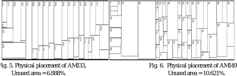
[image:6.612.103.510.237.368.2]The proposed method of PSO-Firefly Algorithm of modules is to be arranged with no overlaps. The benchmark tests included test cases from Compa software package. The graphical plots of the algorithm results for the cases AMI33 and AMI49 presented on Fig. 5 and Fig. 6 respectively. The practical observations show that algorithm gives better results if the number of artificial ants and number of outer iterations is increased. This can be better analyzed from the results presented in Table 1and 2. In Fig. 4 and 5 the results are visualized for each iteration (one line for each value). The ants count values are on horizontal axis by 5 ants per unit and dead space percentage values are on vertical axis
Fig. 5. Physical placement of AMI33, Fig. 6. Physical placement of AMI49, Unused area = 6.888%. Unused area = 10.621%.
Table I: Comparisons For Existing Method And Proposed Method Benchmark
Circuit
Proposed method Existing Method
Wire Length
Area (mm2)
Time (s)
Wire Length Area
(mm2)
Time (s)
Apte 1108.36 44.89 21 1228.75 46.92 23
hp 5428.45 9.19 65 5526.92 9.22 87
Xerox 7156.28 19.02 50 7340.25 19.55 60
Ami 33 2219.17 1.16 435 2338.07 1.28 614
Ami 49 1252.21 31.99 259 1536.56 41.01 310
N10 1092.77 8.66 86 1104.92 9.23 101
N50 989.16 8.22 126 1168.29 9.19 154
[image:6.612.82.531.397.742.2]N100 1012.48 6.22 142 1117.33 8.59 189
Table 2: The Results Of The Proposed Hpsb Method Using Different Α And Β
Benchmark Circuit
Hybrid PSO-FFA
α = 0.2 and β = 0.2 α = 0.5 and β = 0.5
Area (mm2)
Wire Length
Time (s)
Wire Length Area
(mm2)
Time (s)
Apte 47.32 1189.23 27.36 48.09 1256.59 28.98
Hp 10.22 5512.99 26.09 09.22 5445.45 26.45
Xerox 20.11 7325.21 25.12 20.18 7223.53 26.26
Ami 33 01.42 2233.29 107.45 01.49 2322.64 111.32
Ami 49 35.59 1506.84 94.58 38.68 1489.89 92.56
N 10 23.98 1098.26 22.26 24.61 1098.92 23.87
N50 25.33 1149.29 102.49 25.12 1132.12 109.23
Graph 1, 2 and Graph 3 represent the different benchmark circuits value wire length, area and run times
Graph 1. Wirelength Comparisons for Existing Graph 2. Area Comparisons for and Proposed method Existing and Proposed method
Graph 3. Run time Comparisons for Existing and Proposed method
VI. CONCLUSION
The paper successfully presents the first automatic framework for the analysis of circuits for a multitude of design constraints during the partitioning stage of the VLSI design process enabling the design of fault tolerant/testable VLSI systems. Moreover, reliability driven design approach makes the present approach useful in the design of VLSI systems for safety-critical applications. The proposed hybrid PSO-Firefly algorithm overcomes the weakness of conventional PSO algorithm in solving large-scale problems. The MCL strategy is proposed for floor plan representation that explores large search space and the collaboration between PSO and Firefly exploits global and local information greedily.
REFERENCES
[1] Sait, S. M. and H. Youssef (1995). VLSI physical design automation theory and practice, IEEE Press, New York, USA.
[2] P.K. Tripathi, S. Bandyopadhyay and K.S. Pal, “Multi-objective particle swarm optimization with time variant inertia and acceleration coefficients”, Information Sciences 177 (22), pp:5033–5049, 2007
[3] A.S.Mohais, R.Mohais, C. Ward, “Earthquake classifying neural networks trained with dynamic neighborhood PSO”, Proceedings of the 9th Annual Conference on Genetic and, Evolutionary Computation, pp. 110–117, 2007
[4] G.S. Tewolde, D.M. Hanna and R.E. Haskell, “Multi-swarm parallel PSO: hardware implementation”, Proceedings of the 2009, IEEE Symposium on Swarm 200
[5] X.S. Yang, Firefly algorithms for multimodal optimization, Stochastic Algorithms: Foundations and applications, 447 2009, pp. 169–178
[6] Chiu Wing Sham,Evangeline F.Y. Young, “Routability Driven Floorplanner With Buffer Block Planning”, ISPD ’02, San Diege, California, USA, April 7-10, 2002.
[7] Xin-She Yang, “Firefly Algorithm”, Engineering Optimization: An Introduction with Metaheuristic Applications, pp 221-230, Wiley, 2010. [8] Weste, N.H.E. and Harris, D. 2005 CMOS VLSI Design: Acircuits and System Perspective. 3rd ed. Boston,MA: Pearson Education, Inc
[9] G.Sujathaand Dr. Narayanam Balaji “Timing Analysis, Area and Interconnect Length Optimization for VLSI by Using Genetic Algorithm and PSO
Algorithm”, IOSR Journal of VLSI and Signal Processing (IOSR-JVSP), Volume 9, Issue 1, PP. 34-41 e-ISSN: 2319 – 4200, Jan. - Feb. 2019.
[10] G.Sujathaand Dr. Narayanam Balaji “Timing Analysis, Area and Interconnect Length Optimization for VLSI by Using Genetic Algorithm and PSO Algorithm”, International Journal of Applied Engineering Research Volume 14, Number 6, ISSN 0973-4562, pp.1400-1404 Research India Publications., 2019
[11] G.S. Tewolde, D.M. Hanna and R.E. Haskell Multi-swarm parallel PSO: hardware implementation, in: Proceedings of the 2009 IEEE Symposium on Swarm (2009).
[12] V.LeelaRani and M.Madhavi Latha, “Implementation of genetic algorithm for minimum leakage vector in input vector control approach”, IEEE conference, SPACES, January 2015.
[13] S. Venkatraman and M. Sundhararajan “Particle Swarm Optimization Algorithm for VLSI Floor planning Problem”, Journal of Chemical and Pharmaceutical Sciences, 311 JCPS Volume 10, Issue 1, pp:311-317, January - March 2017 .
[14] Singha, T., Dutta, H.S. and De, M., ‘Optimization of Floor- planning using Genetic Algorithm’, Procedia Technology, vol. 4, pp. 825-829.
[15] Yang, XS. and Gonzalez, J.R. A new meta-heuristic bat Inspired –algorithm, In: Nature inspired cooperative strategies for optimization (NISCO 2010) Studies in computational intelligence. Berlin: Springer; 2010
[16] Chen, G, Guo, W, Cheng, H, Fen, X. and Fang, X. 2008, ‘VLSI Floor planning Based on Particle Swarm Optimization” in Proceedings of 3rd IEEE International Conference on Intelligent System and Knowledge Engineering, Xiamen, pp. 1020-1025.
[17] B Abdul Raheem, S Javeed Basha M Sreenu and K.Manisha “Floor planning Using Nature Inspired Algorithms: An Overview” International Journal of Engineering Research ISSN: 2319-6890 Volume No.8, Issue 2, pp: 118-121, March 2019
[18] S. Venkatraman and M. Sundhararajan “Area and Interconnect length Optimization for VLSI Floor Planning Problem By using Harmony Search Algorithm”, International Journal of Recent Technology and Engineering (IJRTE) ISSN: 2277-3878, Volume-7 Issue-6S3, pp: 139-143, April 2019.
[19] K. Jae-Gon and K. Yeong-Dae, “A linear programming-based algorithm for Floor planning in VLSI design,” IEEE Transactions on Computer-Aided Design of Integrated Circuits and Systems, Vol: 22(5), pp. 584-592, 2003.
[20] Rajendra Bahadur Singh, Anurag Singh Baghe and Ayush Agarwal “A Review on VLSI Floor planning Optimization using Metaheuristics Algorithm”, International Conference on Electrical, Electronics and Optimization Techniques (ICEEOT), pp: 1-6, 201
[21] Tsung-Ying Sun, Sheng-Ta Hsieh, -Min Wang and Cheng-Wei Lin “Floor planning Based on Particle Swarm Optimization”, Proceedings of the 2006 Emerging VLSI Technologies and Architectures (ISVLSI’06), pp: 1-5, 2006.
[22] S.Venkatraman and Dr.M.Sundhararajan “Optimization for VLSI Floor planning Problem by using Hybrid Ant colony Optimization technique”, International Journal of Pure and Applied Mathematics, Volume 115, No. 6, ISSN: 1314-3395, pp:637-642, 2017.
[23] Chyi-Shiang Hoo, Kanesan Jeevan Velappa Ganapathy and Harikrishnan Ramiah “Variable-Order Ant System for VLSI multi-objective floor planning” Applied Soft Computing 13 (2013) 3285–3297, pp:3285-3297.
[24] M. Nasir Ayob1 and Fariz Hassan “A Firefly Algorithm Approach for Routing in VLSI” International Symposium on Computer Applications and Industrial Electronics (ISCAIE 2012), pp:43-47, December 3-4, 2012, Kota Kinabalu, Malaysia, 2012.