©IJRASET: All Rights are Reserved
727
Numerical Investigation on Stress and CFD
Analysis of Aircraft Wings for Better Performance
Rajesh Kumar1, Ch. Shalini2
1, 2
CVR college of Engineering, Hyderabad
Abstract: The air foil section is the incarnation of a wing or a lifting surface which is very important in an airplane wing design. While the shape of the air foil changes, their aerodynamic characteristics also change. This investigation deals with a standard symmetrical air foil as reference and the effect of changes in shape due to minor variations in the coordinates. Three new air foil shapes have been produced in this optimisation process. The aerodynamic characteristic results such as the coefficients of lift and drag (Cd, Cl), pressure coefficient (Cp), moment coefficient (Cm) are noted for all three different profiles, produced from the standard NACA 0012.Wortmann fx 63-137 and Clark y air foils are also included in our project. The modus-operandi used in this optimisation process is the Computational Fluid Dynamics (CFD). We have used ANSYS FLUENT and MODAL for flow and stress analysis. Flow changes have been recorded for these air foil shapes and the results are arrived for finding the best air foil that can be advisable.
Keywords: Airfoil, airfoil shape, aerodynamic characteristics, Fluent, Modal.
I. INTRODUCTION
The wing may be considered as the most important component of an aircraft, since a fixed-wing aircraft is not able to fly without it. It is made up of an airfoil which have some cross sectional area. Since the wing geometry and its features are influencing all other aircraft components, we begin the detail design process by wing design. The primary function of the wing is to generate sufficient lift force or simply lift (L). However, the wing has two other productions, namely drag force or drag (D) and nose-down pitching moment (M). While a wing designer is looking to maximize the lift, the other two (drag and pitching moment) must be minimized. In fact, wing is assumed ad a lifting surface that lift is produced due to the pressure difference between lower and upper surfaces. A wing following the laminar stream has much larger thickness in the middle of the camber line. It represent negative weight slant along the stream. So if we maintain the camber I the center, then a laminar stream with high rate high rate at high speed can be achieved.
II. WINGDESIGN
©IJRASET: All Rights are Reserved
728
III.METHODOLOGY
CFD and CAE are the numerical strategy which are used to reproduce physical issues with use of experiments. This is used to inquire about the arrangement without making physical model. In general numerical simulation consists of the following processes. 1) Modelling: After the completion of aerofoil selection, we collected aerofoil coordinate data as per the required dimensions from
aerofoil tools website. By using CREO software, 2D model is generated by importing the coordinates into it. Then the 2D generated model is extruded into 3D model. After modelling different types of aerofoils, then it is imported in ANSYS WORKBENCH for CFD and MODAL analysis. Even other software XFLR is used to study the various characteristics of the aerofoils. The below figures shows the 3D model of NACA 0012 generated in CREO software and the mesh of one of the aerofoil selected.
Fig A: 3D model of NACA Aerofoil 0012 Fig B: NACA 0040 Mesh part
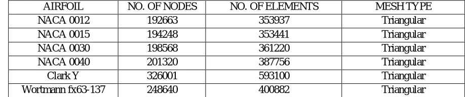
2) Meshing: All the different aerofoils were meshed in Ansys default mesher. Minimum five inflation layers were created around the aerofoils to capture the boundary layers. The above figure shows the best mesh around the aerofoils which we obtained by giving it a fine mesh. The below table shows us the structure of mesh elements of various aerofoil.
AIRFOIL NO. OF NODES NO. OF ELEMENTS MESH TYPE
NACA 0012 192663 353937 Triangular
NACA 0015 194248 353441 Triangular
NACA 0030 198568 361220 Triangular
NACA 0040 201320 387756 Triangular
Clark Y 326001 593100 Triangular
[image:2.612.241.520.210.367.2]Wortmann fx63-137 248640 400882 Triangular
Table 1: No. of nodes and elements of different aerofoils
3) Fluent: After successfully meshing the aerofoils, then they were imported in Ansys Fluent and boundary conditions were given to start the simulation. Various contours of pressure and velocity were obtained for all the different aerofoils. The various boundary conditions applied here are mentioned below.
S.No PROPERTIES VALUES
1 Type of material Aluminium
2 Chord 300mm
3 Span 1m
4 Velocity 133 m/s
5 Solution method Standard k-ɛ
[image:2.612.86.545.434.530.2]©IJRASET: All Rights are Reserved
729
4) XFLR5: After getting the various contours of pressure and velocity Cl and Cd values were determined by using a software called XFLR5. Here in this software we can easily get the graphs of Cl and Cd of various aerofoil and can compare them to get the L/D ratio.
5) Modal Analysis: After successfully iterations of the aerofoils in Fluent it was again imported in Ansys Workbench to find out the natural characteristics or the mode shape and vibration frequencies that are responsible for the vibratory oscillations of the aerofoil. Here self-weight condition was of opted to mainly identify the flutter characteristics of the aerofoil profiles and the means of noise related problems during the flight. Even the structural performance of the aerofoil can be estimated by knowing the modes of the failures.
6) Comparison: After getting all the output results from various software, all the aerofoils were compared to find out the optimum aerofoil which can give better performance and stability.
IV.RESULTANAYSIS
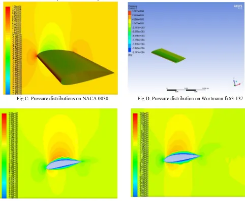
[image:3.612.56.538.255.652.2]From the figures below we can see the different contours of velocity and pressure distribution on different aerofoils. It is clearly seen that there are variations in pressure and velocity on each aerofoil.
Fig C: Pressure distributions on NACA 0030 Fig D: Pressure distribution on Wortmann fx63-137
Fig E:Velocity distribution of Wortmann fx63-137 Fig F:Velocity distribution of NACA 0040
©IJRASET: All Rights are Reserved
730
The aerodynamic coefficients are dependent on their body shape (airfoil section chosen), and also on the attitude (angle of attack), Reynolds number, Mach number, surface roughness, and air turbulence. The results tabulated in Table 5.2 shows the (L/D) ratio of Clark Y and Wortmann airfoils at 3° angle of attack.
Mach No.
REF 1 2 3
(L/D) in % of chord at AOA 3°
12 15 30 40
0.2 21.9 15.5 23.9 30.3
0.3 21.0 15.0 23.2 29.4
0.4 20.5 14.5 22.6 28.5
0.5 20.5 14.0 22.0 27.1
0.6 19.0 12.9 21.6 27.1
Table 4: (L/D) ratio in % of chord of NACA 0012 Table 5: (L/D) ratio in % of chord
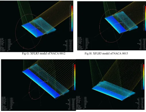
[image:4.612.75.574.130.250.2]The below figures shows the wing design and analysis generated in XFLR5 software. Boundary conditions were applied like Mach number, Angle of Attack, chord length and dihedral angle.
[image:4.612.45.553.302.691.2]Fig G: XFLR5 model of NACA 0012 Fig H: XFLR5 model of NACA 0015
Fig I: XFLR5 model of NACA 0030 Fig J: XFLR5 model of NACA 0040
Mach no. Wortmann f*63-137 Clark y
(L/D) in % of chord at 3 AOA
0.2 61.7 41.5
0.3 60.5 40.3
0.4 59.2 39.1
0.5 58.1 38.0
[image:4.612.44.558.305.481.2]©IJRASET: All Rights are Reserved
731
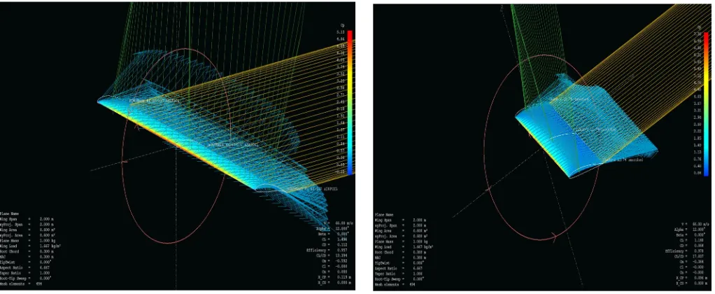
[image:5.612.42.553.76.286.2]
Fig K: XFLR5 model of Wortmann fx63-137 Fig L: XFLR5 model of Clark Y airfoil
[image:5.612.319.571.334.484.2] [image:5.612.43.322.334.488.2]The following figures shows the stress distribution on each aerofil and the toatl deformation in them.
Fig M: Stress distribution of NACA 0012 Fig N: Stress distribution of NACA 0030
[image:5.612.52.555.521.693.2]
©IJRASET: All Rights are Reserved
732
V. CONCLUSION
From the investigation, following conclusions have been drawn.
CFD and MODAL analysis was done on various different aerofoils with different thickness in % of chord. It was found that Wortmann fx63-137 at an angle of attack 12° and Mach no. ranging from 0.2 to 0.6 has the best lift to drag values. From the results obtained from ANSYS FLUENT, it has been found that wortmann fx63-137 has the best pressure and velocity distributions over selected airfoils.We plotted graphs between Cl vs Cd , Cl/Cd vs α, Cm vs α using XFLR5 software. Fig shows the comparison
between selected airfoils. It was found that Wortmann fx63-137 has the highest Cl value at low Cd. From modal analysis, wortmann and clark y has the best resistance to deformation and stresses
VI.ACKNOWLEDGMENT
I am thankful to Dr. T.Murugan who has spared his valuable time and append novel ideas to guide us. I am thankful to our colleagues for providing us appropriate environment required for the paper to complete. I am also thankful to the whole Mechanical Department for their encouragement and cooperation for the successful completion of the paper
REFERENCES [1] Eppler, Richard, Airfoil Design and Data, Springer-Verlag, Berlin, 1990
[2] Abbott I. H. and Von Donehoff A. F., Theory of Wing Sections, Dover, 1959 [3] Anderson J. D., Fundamentals of Aerodynamics, McGraw-Hill, Fifth edition, 2010 [4] Jackson P., Jane’s All the World’s Aircraft, Jane‟s information group, Various years
[5] Blanchard B. S. and Fabrycky W. J., Systems Engineering and Analysis, Prentice Hall, Third edition, 2006 [6] Shevell R. S., Fundamentals of Flight, Prentice Hall, Second edition, 1989
[7] Sadraey M., Aircraft Performance Analysis, VDM Verlag Dr. Müller, 2009 [8] Anderson J. D., Aircraft Performance and Design, McGraw-Hill, 1999