Design of HVAC System for a Commercial
Building by using Radiant Cooling
Mohd Ubaid Ur Rahman1, Dr. Shaik Magbul Hussain
1
M Tech PhD, 2Professor& Hod, Dept of Mechanical Engineering, Nawab Shah Alam Khan College Of Engineering and Technology, Hyderabad, Ts, India
Abstract: The design of air conditioning (HVAC) systems for commercial building by using radiant cooling systems. Radiant cooling system is a promising technique, which is suitable for independent control processes of temperature and humidity. The two main benefits of radiant cooling systems include the potential to save energy and improvement of indoor thermal comfort. The Radiant Cooling with Ceiling system consolidates the pipe network in each panel and the piping are connected to the chiller through these pipes the chilled water will be circulated to the ceiling panels. Ceiling panels are designed in such a way that there would be no condensation occurs at ceiling panels as they are designed below dew point temperature. The radiant cooling panels can work more The surveying data conducted during the design indicate how much of the tonnage required for the whole area with which we can distribute the temperature in the surface through radiant ceiling panels for the proper comfort of the occupants in the space. Our designing .Our calculations determine the coil size too for fixing it at the ceiling; the coil size will determine to fix it at ceiling for connecting it to the pipes which are travelling from the chiller unit by carrying the chilled water throughout the ceiling panels. In our project there is a separate system to provide air for ventilation and for additional cooling for the occupants in the space. These establishments will be really helpful in optimizing and controlling the strategies of HVAC system. The project work includes heat load calculation of the building through hourly analysis program (HAP), duct designing through mc quay duct sizer, pipe sizing through mc quay pipe sizer, drafting of air distribution system.
I. INTRODUCTION
A. Introduction To HVAC
The term HVAC which truncates to heating, ventilation, and air condition, as it has a huge scope? It managed the system utilized for application like heating, comfort cooling, and ventilation and cooling application in commercial areas. It incorporates study of extensive variety of equipment’s from little scale residential application to the huge Industrial applications. The standards or phrasing, terminology of HVAC are taken from the society called as ASHRAE which refers to American society of heating, refrigeration and air conditioning engineers. Nowadays a innovative and better air conditioning system is majorly has the objective with the advancing, human comforts. In these incredible advancements can be made however the extents of further research still subsist. Indoor air quality is a huge constraint in the outline of an aerating and cooling frameworks as it a noteworthy concern worldwide since, it enormously influence the relieve in the work space or in industrial requirements. Majorly the study of indoor air Quality and its effect are mostly concern in the field of an air conditioning The important consideration is conservation of energy resource in decreasing and optimizing the utilization of energy in recently constructed infrastructures and in existing spaces with wanted comfort conditions and indoor air superiority. As this requires a Arrangements of certain disciplinary approach which are to be implemented while designing and an aerating system.
1) Heating: Heating is defines as the procedure of increasing or expanding the warmth of the space Where compared to surrounding heat of the space is gradually bringing down with Standard temperature (25 ºc) respectively. The heating procedure is carried through by Various methods such as equipment’s like boilers, heaters, etc…, heating methods or Consideration are generally they are implemented in countries like USA, Australia , Canada etc..,
2) Cooling: Cooling is defines as the way of lessening the temperature of the air where the Surrounding temperature of that area is higher than the calm temperature by implementing The various standards of refrigeration or heat exchanges to the lower body temperature is Know as cooling.
4) Air Conditioning: Air conditionings describes as the procedure of regarding air in order to control simultaneously its temperature, humidity, cleanliness and distributing and meet the Prerequisites of conditioned space.
B. Introduction on Radiant Cooling
The radiant cooling system is a system using a temperature controlled surface that cools Indoor temperature by evacuation of sensible heat where the half of the warmth happens through the thermal radiation. Generally the radiant cooling systems are concerned in Chilled ceiling beams or panels. With the benefit of convection air cooling and additionally Normal radiant temperature to be attain. Radiant system that utilizes water to cooled the Desired surface are known as hydronic systems .the hrdronic radiant system flow the Cooled water in pipes through an extraordinary mounted panels on a building floor or Ceiling to supply comfortable temperature
C. Statement of Problem
The problem underlying of my project radiant cooling system to examine the indoor temperature and the thermal comfort in a surface where a cooling will be done by radiant cooling with the ceiling panel. An important study in my plan is to look into thermal comfort for people working in the office space, equipment to be cooled. The stature of the floor influences the thermal comfort in the specified area. If the floor height modifies there will be a change in the ratio of convection and radiation. Mean radiant temperature (MRT) calculations are done very complicated because it requires the variation between the incoming air temperature and the incoming water temperature and also requires the leaving air temperature from the room and the leaving water temperature from the room. For cooling, it is critical to maintain the temperature of the external surface of the tubing that carries cooling water lower than dew point temperature to avoid condensation.
D. Research Methodology
In research methodology, for computing the heat load there is standard software HAP (hourly analysis program) which will give the complete report to find cooling conditions capacity to accomplish good indoor air quality as it is a powerful tool. HAP gives adaptable features for outlining hvac system for commercial buildings. As it also offer energy analysis and energy utilization. Another tool used is duct sizer which is utilized for calculating duct sizes and the area and pipe sizer is utilized to cal calculate the pipe size for the flow of water through it. ASHRAE standards are available to take the values and expressions to find the coil size which we utilized in ceiling panels.
II. HVAC SYSTEM
A. Radiant Cooling From Chilled Slabs
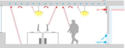
Cooling originates from the structure of the building like slabs, in view of this it is named as thermally active building system (TABS). Transfer of cooling in this kind of Radiant cooling system with integrated slabs to the area as of the floor or ceiling. Europe since last couple of tens the heating is as same as floor cooling respectively. The radiant air conditioning which is available in terms of chilled slabs or ceiling panels, to attain the benefit of convective conditioning and the mean radiant temperature .because of cool air sinks, a chilled ceiling panel wills cold the air that will make itself to spread into the space through specialized panels. There are so many advantages to deliver the cooling with ceiling. It is more agreeable to leave roofs presented to a room than floors, as it will increase the capability of thermal mass. Floors have furniture, covers, and decorations that decline the feasibility of the association. At the point when guideline of a cooling talks in Radiant cooling system it utilizes the regular purpose of rule to convey the cooling to ceiling or through the floor or even with the walls since it ingests the warmth emanated through the rest of the way. The following diagram is clearly showing us the chilled ceiling
[image:2.612.201.414.630.712.2]15 behaves as temperature go down for every origin throughout the space which includes likewise people present in the room, solar radiation, the equipment loads and the wall etc.
The radiant cooling system which normally utilizes chilled water, as it is a hydronic system which uses water running in the pipes channel in thermal contact with the airfoil. The circling water just should be 2-4°C underneath the coveted indoor air temperature. The high temperature is expelled by the water falling in the pressure driven circuit once the heat from various starting points within the zone is engaged by the effectively cooled surface –ceiling which is on the roof, base or walls.
B. Design of HVAC System
[image:3.612.197.416.222.307.2]1) Basic On Radiant Cooling System Utilizing Bore Wells: To keep up slab temperature and soil temperature equal with an association comprises of two bore wells from which one is associated with radiant slab and water is pumped through it and another drag well is linked with the heated water that leaves the radiant slab. During the time the temperature of earth beneath 12ft is consistent which is a mean temperature of particular geographical limitation is. The underneath figure demonstrates recorded room temperature. Utilizing stack impact ventilation framework, the way is likewise ventilated.
Figure 2.2-Radiant cooling system utilizing bore well
Firstly we should have to see the geological ground conditions at the site .from these surveys we can get the ground parameters required by this we can send the water from the bottom to the ceiling panels by which a greater savings be able to be accomplished as the water is a natural resource.
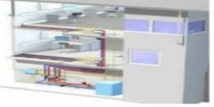
[image:3.612.199.414.443.522.2]2) Radiant Cooling Systems Utilizing Cooled Water: In this plan, the chiller creates the cool water by which the slab is chilled. The dew point temperature of breeze is progressively more when contrasted with the cool water temperature which was provided to a radiant slab. But the natural air climatically outline development can accomplish C in space with no air dealing with unit by these systems. At the point when natural air is pumped it limits to 20% of power required for air taking care of units.
Figure 2.3- radiant cooling system utilizing cool water
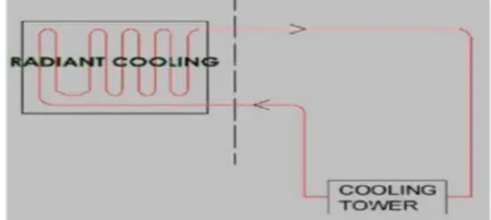
3) Basic Section Radiant Cooling System Utilizing Cooling Tower: To keep up the slab temperature close to wet globule temperature otherwise called wet knob approach, the slab of radiant cooling is connected to a cooling tower. The dry globule and wet knob temperature very change in hot and dry atmospheres so this plan cools the space well impressively. The high measure of warmth is emanated from sun to largest amount of structures to possess space is overwhelmed by utilizing this framework
[image:3.612.194.419.616.717.2]4) Mean Radiant Temperature (MRT): As per ASHRAE (American Society of Heating, Refrigerating and Air – Conditioning Engineers) Standard 55-2010 characterizes six factors that influence warm human solace, they are (air temperature, radiant temperature, humidity, velocity of air, metabolism and clothing). Since the velocity of air, and metabolism and clothing are inhabitant reliant, initially just the air temperature, humidity factor, velocity of air, metabolism and clothing these can be observed and controlled by the HVAC system. Conventional aerating and cooling system normally screen and control air temperature, humidity, velocity of air of these space condition, overlooking radiant temperature.
C. Control Selection For The Radiant Cooling Systems 1) Building Control Strategies
[image:4.612.195.406.214.320.2]a) Outdoor temperature sensor on the northern side of the building not exposed to sunlight.
Figure – 2.5 control strategy of a building
b) The moisture and temperature sensors are kept in each zone which is used to monitor dew point temperature throughout the
space.
c) As the humidity sensors are placed in various rooms to calculate relative humidity in various rooms.
d) Air sensing and temperature sensing thermostats are placed within each zone to manage air delivery for quick response cooling
and local dehumidification. And temperature sensors manage to adjust the flow of temperature in required zone as it will indicates on the thermostat.
e) Both detectors are frequently blended in single unit. Appropriate BMS based smart control systems are used.
III. BUILDING DETAILS
A. Building Description
In this project work the type of building for which a radiant cooling system with ceiling panels is designed and implemented, is a commercial type of application that is the buil -ding which is chosen is intended as to be used as a commercial building i.e. office buil -ding. The orientation of the building is such that as it is facing towards north direction Building is provided with complete glass portion or it may be called as envelope
B. Floors And Areas
The building comprises of four floors i.e. a ground floor, first floor, second and third floors respectively. As my project designed for a commercial space the whole amount of area where my radiant cooling system has been planned is about 84218sqft. And the TR 440 tonnage .The following are the areas block wise as my commercial building is divided into two sub portions at each floor. Ground floor partition 1 : 8000sqft
Ground floor partition 2 : 9340sqft First floor partition 1 : 10895sqft First floor partition 2 : 10313sqft Second floor partition 1 : 10525sqft Second floor partition 2 : 10341sqft Third floor partition 1 : 12152sqft Third floor partition 2 : 12152sqft
C. Plans Pictures 1) Ground Floor Plan
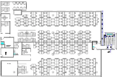
[image:5.612.206.411.268.400.2]Figure 3.1: building plan (ground floor- partition 1)
Figure 3.2 : building plan (first floor – partition 1)
Figure 3.3 building plan( second floor –partition 1)
[image:5.612.208.411.427.551.2] [image:5.612.204.407.582.716.2]D. Designed Floors
Figure 3.5 building design plan (ground floor-partition 1)
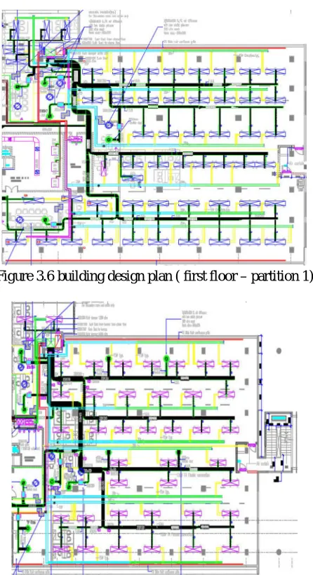
[image:6.612.196.419.292.702.2]Figure 3.6 building design plan ( first floor – partition 1)
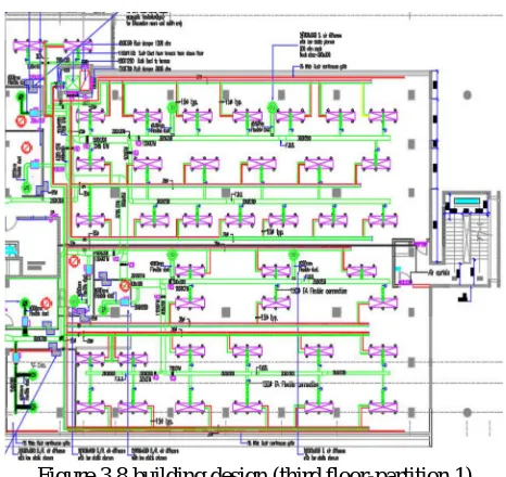
Figure 3.8 building design (third floor-partition 1)
IV. HEAT LOAD CALCULATIONS
To find the heat load of a office space we will need to know the following things:
1) Area of the space
2) The number walls facing to the solar
3) The number of occupants
4) The lighting load
5) The equipment load
6) Area of the unconditioned partition
A. E 20 Sheet For The Ground Floor Partition 1 Heat Load
B. HAP
The valuation of heat load calculations is also done with the HAP software.
Hourly Analysis Program (HAP) is a PC based programming which encourages architects to plan a HVAC framework for different structures. As it contains different tools in which one is used for load calculations and for designing the systems another one it is help full for simulating use of energy and to find the cost of energy to be spent for a building. The functionality method to find the load it goes with the ASHRAE endorsed methods and these methods for energy analysis with hour by hour energy simulation approaches.
HAP program comes as two same but in two different products.
1) HAP System Design Load
2) 2. HAP
C. HAP Summary Reports Of Ground Floor
2) Air System Sizing Summary For First Floor Partition 1
3) Air System Sizing Summary For Second Floor Partition 1
V. DUCT DESIGNING
The duct element is an important part of an air conditioning system and is categorized under the air distribution system. The ducts are the enclosed passage way that are meant to carry the conditioned air to the space from the system outlet and also to carry away the exhaust or return air from the spaces back to the system for conditioning.
It is important that the design of duct system must be carefully done as it greatly affects the design of air conditioning system. Also, the execution of the duct work must be done under close supervision as any errors in the duct installation may lead to inefficiency of the plant. The main factor to be designed in terms of duct designing is the size of the duct that is suitable to convey the desired amount of air at proper flow rate and pressure. The size
should be optimum corresponding to the air flow. Any disparity in the design of duct may lead to drawback like surplus cost expenditure, noisy operation, and excess energy usage. The air flow rate should be maintained throughout the space as per the cfm provided, also the pressure and the velocity which ensure the effective air distribution in a room and enhance the comfort.
A. Classification Of Ducts
Based on the shape of duct, the duct are classified as
1) Circular or round ducts
2) Rectangle or square ducts
3) Oval ducts
B. Methods Of Ducting Designing
There are mainly three methods of duct designing they are;
1) Constant friction loss or equal friction method
2) Velocity reduction method
3) Static regains method
C. Equal Friction Method
D. Pipe Sizing
The cooling water pipe sizing can be done either manually using the schedule 40 chart from ISHRAE or by using the software named pipe sizer developed by Mc Quay. The main consideration or the input parameters in the design of cooling water pipe size are the water consumption rating and the head loss due to friction. The water consumption rating is defined in terms of gallons per minute (GPM) and the friction loss is defined in terms of feet of water per 100 feet (ft/100 ft). Typical design standards of these two parameters are specified below. Water consumption rate – 3 gpm / TR for closed cycle Friction loss – upto 2.5ft per 100ft for commercial applications
VI. CONCLUSION
A complete design of a radiant cooling air conditioning system is presented under this project work and the following results are obtained during the course of this project. The net heat load estimated for the commercial building is 440 TR throughout the floors. The purpose of the project was to cool the spaces through radiant cooling frameworks using the ceiling panels, as this system is also called as hydronic system due to utilization of water. The cooling water pipe size is obtained as 4 inches in diameter corresponding to the total water consumption rating of 138 gpm. For the interior region with internal load, the cooling rate difference ranged from 7%-26% at surface level as its mainly depends on fraction of internal laods. The pump capacity determined is 38 H. P This will results in the higher radiant fraction in the process of heat gain generate bigger difference in peak cooling rates. As in this we are using ceiling panel 4.5% amount of cash been saved through ceiling panel when compared to other systems. Material cost is 40% less. The consumption of electricity usage is 30% when compared to the other traditionalHVAC systems the result has shown 50% more efficiency. The project is productively consummate and given reasonable results.
REFRENCES
[1] Refrigeration and air conditioning by domkundwar, aurora.
[2] Lehmann, B.M gwerder, V. dorer and F. renggli (2011) thermally activated building system. [3] ISHRAE handbook 2007
[4] ASHRAE handbook 2001 [5] www.mcquay.com