Abstract.—This paper proposes a technique to design the switching angles in a PWM AC voltage controller using genetic algorithms (GA) and distributed artificial neural network (ANN). In the proposed technique, GA is used to evaluate the turn on and turn off angles of PWM pattern to reduce the low order harmonic content in PWM output voltage. The results from GA are then used to train the distributed ANN. The advantages gained from the proposed technique are the reduction of complexity of training process and the improvement of the ability of the ANN. In addition, the total harmonic distortion of voltage, which calculated from the low order harmonic content, is adopted in the proposed fitness function. Thus, the load value is not necessary to be known before stating the proposed technique. Simulation results show that the proposed technique is superior to the conventional fixed-duration pulse technique.
I. INTRODUCTION
Phase control technique can be used to control the output voltage of AC voltage controller. The principle of this technique is the phase control in line commutated switching device. However, this technique performs a poor performance in terms of high harmonic distortion and low input power factor. Several years ago, various techniques were proposed to improve the performance of PWM converter [2, 3]. Garnal and Mostafa [2] proposed a generalized symmetrical angle PWM technique for an AC voltage controller. Fedyczak et. al. [3] presented the comparison of basic properties of single-phase serial AC voltage controllers using a bipolar PWM chopper. The comparative study of the bipolar PWM AC matrix chopper based on full-bridge topology and the bipolar PWM AC matrix-reactance chopper (MRC) based on Cuk B2 topology and auxiliary transformer were described in their paper.
Manuscript received January 12, 2011. This work is supported by the research fund from King Mongkut’s Insitute of Technology Ladkrabang , Thailand.
Pattaraporn Jitta, Dr. Somyot Kaitwanidvilai and Dr. Atthapol Ngaopitakkul are with the Electrical Engineering Department, Faculty of Engineering, King Mongkut’s Insitute of Technology Ladkrabang, Thailand. (email : [email protected])
Dr. Somyot Kaitwanidvilai is also with the Center of Excellence for Innovative Energy Systems, King Mongkut's Institute of Technology Ladkrabang, Bangkok 10520, Thailand.
Artificial intelligent techniques were adopted in many research areas including mechatronics, electronic, power electronics, etc. Several artificial intelligent techniques such as genetic algorithms (GAs), particle swarm optimization, neural networks, etc. were proposed for solving the complex problems, which cannot be easily solved by any analytical methods. Somyot and Piroj [10] proposed the genetic algorithms to evaluate the optimal switching angles of PWM pattern so that the total current harmonic distortion and the voltage error are minimized. However, in their technique, the load value must be known before starting the algorithm, and the complexity of single artificial neural network (ANN) used in their paper limits the size of training set. To overcome these problems, this paper proposes the genetic algorithm (GA) to analyze the optimal switching angles at the specified voltages, and uses the distributed neural network to approximate the other angles in the specified range. In addition, the fitness function using low order harmonic content of voltage is proposed; thus, the load value is not required for the proposed algorithm.
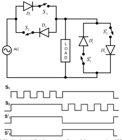
II. CONVENTIONAL PWM AC VOLTAGE CONTROLLER PWM AC voltage controller is a power electronic circuit which can be used to control the electrical power from AC source to electrical load. As shown in Fig. 1, S1 and S2 perform as the switching devices controlled by the PWM pattern, and S'1 and S'2 perform as the free-wheeling devices. The Pulse Width Modulation (PWM) control [2] has higher efficiency than the phase control technique; however, the drawbacks of this control scheme are the high switching loss and the complex of control circuit. Normally, the PWM pattern is designed by the conventional fixed duration pulse technique, which the width of pulse controls the output rms voltage of the circuit. Fig. 2 shows an example of the output voltage waveform from the conventional technique. In this figure, the switching frequency of PWM is 1 kHz; the AC input voltage is 220 V, 50 Hz, and the numerical calculation of the rms voltage is 160.9 Vrms.
Switching Angle Design for Pulse Width
Modulation AC Voltage Controller
Using Genetic Algorithm and Distributed
Artificial Neural Network
1
D S1
2
S D2
1 D 1 S 2 S 2 D
Fig. 1 Single-phase AC voltage controller and the conventional PWM signal [1]
Fig. 2 Output voltage waveform of the conventional PWM AC voltage
controller with the output rms voltage of 160.9 V
III. GA AND DISTRIBUTED ARTIFITIAL NEURAL NETWORK
A. Genetic Algorithms (GAs)
Genetic algorithm is a searching algorithm which can be used to solve any optimization problem by representing the candidates of the answer by chromosomes. The adjustment of the chromosomes is done by the concept of evolutionary operations. Fitness is a function which uses to describe the satisfaction level of the chromosome. To generate the next generation population, several chromosomes are selected to be the parents; chromosome with high fitness has a high chance to be selected. A selected genetic operation is then adopted to form a new chromosome. There are 3 types of genetic operators, reproduction, crossover and mutation. More information of GAs can be seen in [8].
Generally, the output waveform of AC voltage controller is non-sinusoidal waveform, and then both the voltage and the current from this circuit normally contain the harmonic content. It is well known that the current harmonic causes the current distortion, low-input power factor and loss. The current distortion can be evaluated from the summation of the current harmonics as shown in (1). Assuming the RL
load value is known, the fundamental and harmonic currents of the AC voltage controller can be determined by (2). All components can be determined by applying the Fast Fourier Transform (FFT). Additionally, the total voltage harmonic distortion can be determined by (3).
2 2 1 n n i I THD I
(1)2 (2 )2
n n
V I
R
nfL
(2)
2 2 1 n n v V THD V
(3) where THDi is the total current harmonic distortion,THDv is the total voltage harmonic distortion,
n
is the nth harmonic order,V In, n are the rms values of n
th harmonic voltage and current, respectively,
V I1, 1 are the rms values of fundamental voltage
and current, respectively,
R L, are the resistance and inductance values of
load, and
f
is the frequency of the fundamental voltage.In our technique, the calculation of THDvincludes the harmonics from 2nd to 13th order for considering only low
order harmonic content. The AC voltage controller is used to control the rms output voltage which can be evaluated by (4). 2 1 rms n n V V
(4)As known by many researchers, the increasing of THDi
causes the reduction of input power factor. The relationship between THDi and input power factor can be seen in (5).
2
1 . . cos
1 i
p f
THD
(5)
where
p f
. .
is the input power factor, and
is the load angle.B. The proposed GA based PWM AC Voltage Controller
In the proposed technique, the optimal switching angles (α) in PWM signal are attempted to be determined so that the total voltage harmonic distortion calculated from the specified low order harmonic content is minimized, and the rms output voltage is achieved. In the proposed technique, the following parameters must be specified before starting GA. M is the number of pulses in a quarter cycle of PWM
waveform,
V
drms is the desired rms output voltage,1 1 2 2
[
on,
off,
on,
off...
Mon,
Moff]
is the set ofswitching angles in a quarter cycle of PWM, and
,
xon xoff
are the turn-on and turn-off angles of the xth [image:2.595.73.269.52.276.2] [image:2.595.62.269.305.458.2]on
2
on
1
off
1
2
offMon
MoffFig. 3 Example of output voltage of PWM AC voltage controller which
M = 3
Fig. 3 presents the example of PWM waveform that has the number of pulses in a quarter cycle (M) = 3. This waveform
is symmetrical. The boundary of each switching angle can be specified easily. The details of specifying boundaries of the angles can be seen in [10]. In this problem, α is the chromosome in GA, and the equation of fitness function is modified as the following:
1
v drms rms
fitness
THD V V b
if
V
drms
V
rms
a
k if
V
drms
V
rms
a
(6)Where
V
rmsis the rms output voltage of the PWM AC voltage controller with the switching angle (α),V
drmsis the desired rms output voltage,a
is the acceptable value of the voltage error calculated from the absolute of the difference betweenV
drmsandV
rms,b
is the specified number which is used to avoid the equal to zero of the denominator, andk
is the low value number which is assigned when the rms output voltage is not within the specified bound,a
.
In this research work, the parameters in (6) are
specified as follows:
a
=1,b
=0.001 andk
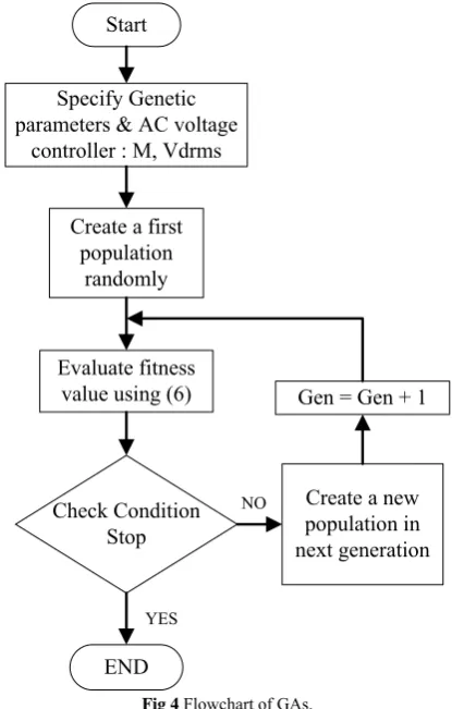
=0.1. These values can be adjusted properly depending on the design. Fig. 4 represents the flowchart of the proposed technique. The stopping condition is specified by a maximum generation. This procedure can be summarized as follows:Step 1 Specify the genetic parameters, e.g. operation
probability, population size, maximum generation, M, Vdrms,
etc.
Step 2 Create the first population randomly.
Step 3 Evaluate the fitness value of each chromosome (α)
by (6). Select the chromosome which has the maximum fitness value as the solution of current generation.
Step 4 When the current generation is less than the
maximum generation, find a new population by genetic operators and then return to step 3. If the current generation is the maximum generation, then stop. The chromosome that has the maximum fitness value is the optimal solution of the problem.
NO Start
Specify Genetic parameters & AC voltage
controller : M, Vdrms
Create a first population
randomly
Evaluate fitness value using (6)
Check Condition Stop
END
Gen = Gen + 1
Create a new population in next generation
YES
Fig 4 Flowchart of GAs.
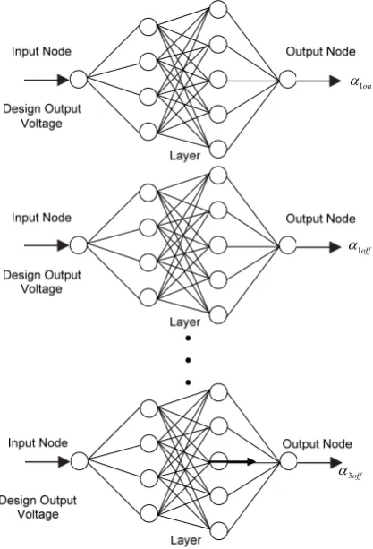
B. Distributed artificial neural network
[image:3.595.60.288.56.248.2] [image:3.595.322.530.62.388.2]1on
1off
3off
Fig. 5 Distributed Artificial Neural Network for AC voltage Controller
IV. THE ANALYSIS AND SIMULATION RESULTS The parameters in our simulation study are specified as follows: the input voltage is 220 Vrms, 50 Hz, output voltage
[ 40, 210], RL load: R = 240 Ω, L = 300 mH, M = 3, cross-over probability = 0.6, mutation probability = 0.1, population size = 1000, maximum generation = 20, and the angle
3off is assigned as 90°. Examples of the voltage and current waveforms are shown in Fig. 6.(a)
(b)
(c)
(d)
(e)
(f)
Fig. 6 Examples of waveforms from the proposed technique and the technique in [10]
(at 180 V, R = 240 Ω, L = 300 mH) (a) Current waveform [10],
(b) Current waveform (the proposed technique), (c) Voltage waveform [10],
(d) Voltage wave form (the proposed technique), (e) Spectrum of current waveform [10],
[image:4.595.53.262.51.358.2] [image:4.595.80.246.503.759.2]Figs. 6(a) to 6(d) show the waveforms at the desired voltage 180 V. As seen in these figures, the waveforms from the proposed technique and the technique in [10] are different. However, considering Figs. 6(e) and 6(f), the low order harmonic content of the proposed technique is better than that of the technique in [10].
[image:5.595.46.292.197.389.2]Fig. 7 shows the total harmonic distortions of current when the voltage output is varied from 40 to 220 V by stepping 2 volts for each step. Clearly, our proposed technique is better than the fixed-duration pulse technique in terms of lower THDi.
Fig.7 THDi of the AC voltage controllers controlled by using the
conventional PWM, GA-ANN in [10], the proposed PWM at load R = 240
Ω, L = 300 mH
[image:5.595.50.288.545.663.2]Table 1 shows the comparison between the proposed and the conventional techniques. As seen in this table, the number of nodes and the training time of the proposed technique are lower than the conventional ANN [10]; however, the %error of voltage from the proposed technique is increased.
Table 1 Number of nodes, time and mean of voltage error of the
proposed technique and the conventional PWM
Description Distributed ANN ANN [10] Number of nodes
in the hidden layer
16 22
Time (second) 13.16 19.27
Mean of Voltage error (%)
3.38 1.54
V. CONCLUSIONS
As seen in the simulation results, the proposed GA and the distributed artificial neural network can be applied to the AC voltage controller, and the performance obtained from the proposed technique is better than that of the conventional fixed-duration pulse PWM. The proposed technique uses the low order voltage harmonic content to calculate the THDv for the fitness function. Thus, the load value is not necessary for our proposed technique. In addition, based on the concept of distributed ANN, the training time and the number of nodes in the network are
reduced.
ACKNOWLEDGMENT
This research work is supported by the research fund from King Mongkut's Institute of Technology Ladkrabang.
REFERENCES
[1] RASHID M.H.: “Power electronics circuit devices and applications” (Prentice-Hall, 1993, 2nd edn.)
[2] HASHEM M., DARWISH K.: “Generalized symmetrical angle PWM technique for AC voltage controller”. Power Engineering Conf., UPEC 2004, September 2004, vol. 2, pp. 898-901.
[3] FEDYCZAK Z., JAHKOWSKI M., SZCZESNIAK P.: “Comparison of basic properties of single phase serial AC voltage controller using bipolar PWM chopper”, Power Electron Appl., 2005, 1, pp. 1-10 [4] KAITWANIDVILAI S., KANPRACHAR S.: “Harmonic reduction in
AC cyclo-converter using a genetic algorithms”. ICEMC, Thailand, 2005
[5] AL-OTHMAN A.K., AHMED N.A., AL-KANDARI A.M., EBRAHEEM H.K.: “Selective harmonic elimination of PWM AC/AC voltage controller using hybrid RGAPS approach”, Int. J. Electr. Conput. Syst. Engng., 2007, 1, (4), pp. 227-233
[6] HWANG W.R., THOMPSON W.E.: “An intelligent controller design based on genetic algorithms”. Proc. 32nd IEEE Conf. on Decision and
Control, December 1993, vol. 15, (17), pp.1266-1267
[7] RAO S.S., SHAILAJA N.: “Improving voltage regulation and harmonic elimination using genetic algorithms in PWM choppers”. INTELEC, 2005, pp. 449-454
[8] NEGNEVITSKY M.: “Artificial intelligence, a guide to intelligent systems” (Addison Wesley, 2005, 2nd edn.)
[9] TENG C., GEORGE C.S.: “Neural fuzzy systems” (Prentice-Hall, 1999)
![Fig.7 THDiconventional PWM, GA-ANN in [10], the proposed PWM at load R = 240 of the AC voltage controllers controlled by using the Ω, L = 300 mH](https://thumb-us.123doks.com/thumbv2/123dok_us/1295434.658846/5.595.46.292.197.389/fig-thdiconventional-pwm-proposed-voltage-controllers-controlled-using.webp)