647
©IJRASET: All Rights are Reserved
An Improved Gateway-Based Energy-Aware
Multi-Hop Routing Protocol for WSNs.
Nitendra Singh1, Dr. Sanjay Kumar Yadav2
1
Department of Computer Science & IT, SHUATS, Allahabad, India.
2
Associate Professor, Department of Computer Science & IT, SHUATS, Allahabad, India
Abstract: In a large scale WSN the nodes which are nearer to sink are always used for forwarding packet from all other distant nodes. Due to this, the nodes which are nearer to sink are out of energy very soon and an energy hole is created near the sink and the sink becomes unreachable, while maximum nodes in the network are still alive. In this research work a gateway based protocol has been proposed, which is an improvement over the M-GEAR protocol. In the proposed work the base station is considered to be located outside the network area. The sensors are randomly based and based on threshold levels are divided into six parts. The sensor nodes below the threshold are in direct communication with the gateway node while those above the threshold level use clustering hierarchy similar to those proposed in LEACH for communication. The results are compared with the existing protocol and fares well in terms of increased lifetime, throughput and residual energy.
Keywords: Wireless Sensor Networks, Network Lifetime, Throughput, Residual Energy, Clustering protocol.
I. INTRODUCTION
648
©IJRASET: All Rights are Reserved
M-GEAR[1] proposes the idea of dividing into network area into logical regions, to efficiently utilize individual sensor node energies. The network area has been divided into four distinct regions which use different communication hierarchy in different regions. Nodes in one region communicate directly to BS while nodes in region 2 communicate directly to gateway node. Nodes in other two regions use clustering hierarchy and sensor nodes transmit their data to gateway node through their CHs. Gateway node assists in defining clusters and issues a TDMA schedule for CHs. Each CH issues its own TDMA schedule for its member nodes.In this paper, an improvement over M-GEAR protocol has been presented, which divides the network area into six different logical regions based on a threshold level of their energies.
II. RELATED WORK
649
©IJRASET: All Rights are Reserved
III. MOTIVATION
Wireless Sensor Network (WSN) due to its potentially large application area emerged as a premier research topic. Usually the WSN once deployed, works in an unattended manner and each sensor node has limited battery capacity. So after each operation a node comes closer to death which finally brings the whole WSN's operation to a halt. So energy is the main constraint for any application using WSN. In a large scale WSN the nodes which are nearer to sink are always used for forwarding packet from all other distant nodes. Due to this, the nodes which are nearer to sink are out of energy very soon and an energy hole is created near the sink and the sink becomes unreachable, while maximum nodes in the network are still alive. Sensor node are densely deployed in wireless sensor network that means physical environment would produce very similar data in close by sensor node and transmitting such type of data is more or less redundant. If sensor nodes of same application and at minimum distance between them alternatively perform data collecting, processing and communication then we can able to transmit information to the base station for longer time. Thus network lifetime will be improved.
IV. NETWORK MODEL
The first order radio model is used in many researches on wireless sensors networks. Energy dissipation takes place, while
transmitting and receiving the data and energy consumption for short distance communication is ‘d2’ when propagation is done in
line of sight and ‘d4’ when transmission is done for the long distance due to multipath fading propagation. It works on the route
measurements and sensing takes place constantly resulting in steady volume of data being transmitted to the sink. The following assumptions are considered in an analytical implementation:
A. Base station remains fixed: Wireless sensors are densely populated in the network area and are static. Number of clusters according to the network is predetermined for the network. The nodes will pass the data on the predefined paths, in which clusters and the cluster heads are numbered according to the distance based on received signal strength.
B. Some sensors are located farther away from the base station due to which, the cluster head will consume the ‘d4’ energy for
transmitting l bit data for direct transmission. Thus, data is transmitted through multiple hops and finally reach the base station by clusters very near to the base station
C. Links in the path are symmetric i.e. same power is required for the communication between any two nodes. No changes in the
topologies and the loads are considered.
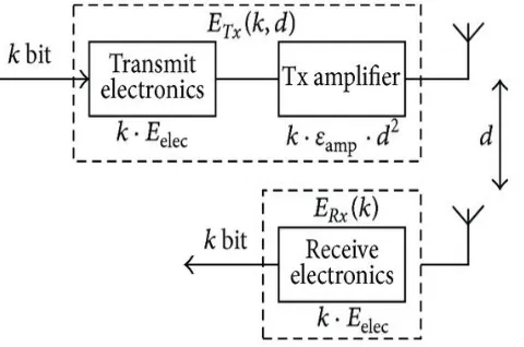
D. Thus, to transmit a message of length to a distance d, the transmitter energy is given as:
d0 = sqrt(Emp/Efs) (1)
if d < d0,
Etx(k,d)=Eelec*k+Emp*k*d4 (2)
If d > d0
Etx(k,d)=Eelec*k+Emp*k*d4 (3)
Receiver Energy:
Erx(k)=Eelec*k (4)
[image:3.612.191.431.553.712.2]Where Eelec is the energy dissipated in transmission and reception, Efs and Emp are free space and amplifier energy respectively.
650
©IJRASET: All Rights are Reserved
[image:4.612.161.458.161.466.2]The above diagram shown in Figure 1, shows a graphical representation of a first order radio model. The transmitter and receiver use the same kind of electronic circuitry and thus their energies are accumulated as Eelec, for each data bit transmitted. The sensor nodes are thus symmetric to each other.
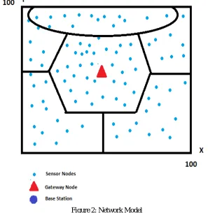
Figure 2: Network Model
The network model used in this research work is as shown in the figure 2. S sensor nodes which are deployed randomly in the
network area. The i-th sensor node is represented by si and consequent sensor node set S= s1,s2,..., sn. All the sensor nodes are
assumed to be homogenous. The gateway node is placed at the center of the network of the network and is rechargeable. The Base station is placed outside the network area.
V. PROPOSED WORK
The proposed work is takes into account geographical positioning of the network area. The network area consists of homogenous sensor nodes are used that are distributed randomly in the network area. After deployment of nodes, every node forwards its location to the base station. The base station calculates the distance of each node and save all information of the sensor nodes into the node data table. The node data table consists of distinctive node ID, Residual energy of node, and its distance to the BS and gateway node. The same topology is being used in this proposed work. The algorithm has been shown below.
A. Set Random Position of Nodes.
1) Set Position of gateway node:- At the center of Network area. X-co-ordinate- M/2, Y-Co-ordinate-M/2;
2) Set Position of Base Station:- X-Co-ordinate- M/2; Y-Co-ordinate-M+M/10.
3) Calculate Distances of each nodes from base station and gateway node.
B. Set up Phase.
651
©IJRASET: All Rights are Reserved
2) Define the node region:- Region 1 nz1=(dBS<=d0).*id Region 2 nz2=(dGS<=d0).*id
Region 3 nz3=(y>=yg & dBS>d0).*id; Region 4 nz4=(y<yg & dGS>d0).*id;
Region 5 (dGS<=d0).*id& ndist =< d0
Region 6 (dGS<=d0).*id& ndist> d0
C. Running Phase
1) Initially every node has probability to be elected has cluster head.
2) Initialize the rounds. Simulation is carried out for 7000 rounds.
3) The selection Probability is given as:
T=p/(1-p*mod(r,1/p))’ (6)
4) Where T is threshold probability, p = the desired percentage of CHs and r = the current round, C = set of nodes not elected as CH
in current round.
5) Calculate node distance to cluster head.
6) For every round calculate energy and threshold for cluster head selection.
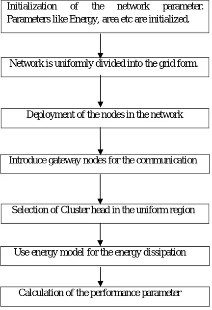
Initialization of the network parameter.
Parameters like Energy, area etc are initialized.
Deployment of the nodes in the network
Selection of Cluster head in the uniform region
[image:5.612.199.415.327.643.2]
Figure 3: Flow chart of the proposed work
VI. PERFORMANCE EVALUATION
A. Simulation Setting
In order to evaluate the performance of the proposed protocol it has been implemented and simulated using MATLAB. A wireless sensor network with 100 nodes distributed randomly in 100m X 100m field. A gateway node is deployed at the center of the sensing
Network is uniformly divided into the grid form.
Introduce gateway nodes for the communication
Use energy model for the energy dissipation
652
©IJRASET: All Rights are Reserved
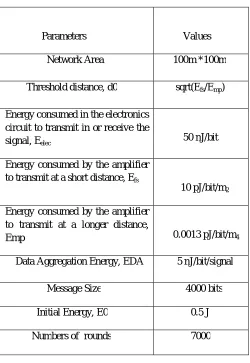
field. The BS is located far away from the sensing field. Both gateway node and BS are stationary after deployment. The table 1 below shows the simulation parameters.
Parameters
Values
Network Area 100m *100m
Threshold distance, d0 sqrt(Efs/Emp)
Energy consumed in the electronics circuit to transmit in or receive the
signal, Eelec 50 nJ/bit
Energy consumed by the amplifier
to transmit at a short distance, Efs
10 pJ/bit/m2
Energy consumed by the amplifier to transmit at a longer distance,
Emp 0.0013 pJ/bit/m4
Data Aggregation Energy, EDA 5 nJ/bit/signal
Message Size 4000 bits
Initial Energy, E0 0.5 J
[image:6.612.182.432.110.473.2]Numbers of rounds 7000
Figure 4: Network parameters
B. Performance Parameters:-
1) Network Lifetime:- It is the time interval from the start of the network operation till the last node die.
2) Throughput:- To evaluate the performance of throughput,the number of packets received by BS are compared with the number of packets sent by the nodes in each round.
3) Residual Energy:- The residual battery energy of network is considered in order to analyse the energy consumption of nodes in each round.
C. Simulation Result and Analysis
In this sub-section we show the simulation results.We compare our results with M-GEAR and LEACH protocols as shown in below figures.
653
[image:7.612.136.456.91.338.2]©IJRASET: All Rights are Reserved
Figure 5: Percent of Alive nodes v/s rounds
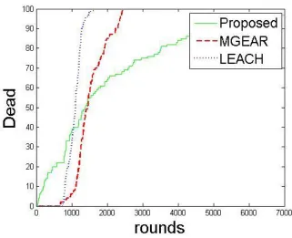
Figure 6: Dead Nodes v/s Rounds
[image:7.612.136.457.381.642.2]654
©IJRASET: All Rights are Reserved
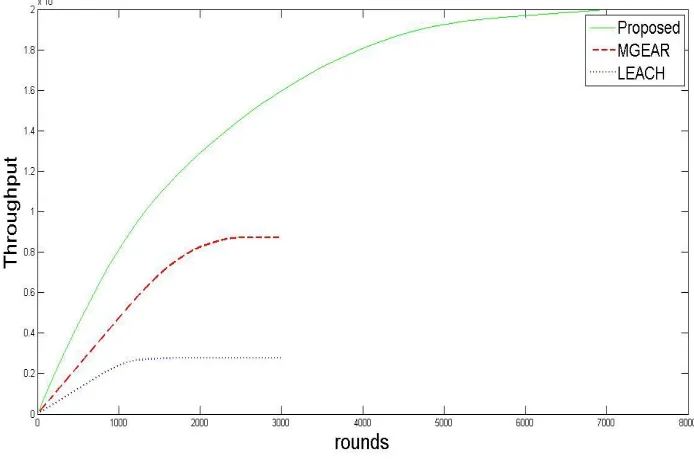
[image:8.612.132.479.131.363.2]2) Throughput: Average packet sent to BS are assessed through extensive simulations. Simulation results of our proposed protocol illustrate increased throughput. Sensor nodes near gateway send their data directly to gateway, similarly nodes near BS transmit data directly to BS.
Figure 7: Throughput v/s rounds
3) Residual Energy: Figure 8, shows average residual energy of network per round. It shows number of packets of data transferred between sensor nodes and the base station. In this comparison as well, the proposed protocol shows the minimum energy consumption as compared to LEACH and M-GEAR.
655
©IJRASET: All Rights are Reserved
Residual energy resembles energy remaining in the sensor nodes after each round. The proposed protocol is able to maintain a considerable residual energy for operations upto 7000 rounds as compared to LEACH and M-GEAR which spent out the energy after 1500 and 2500 rounds approximately.
VII. CONCLUSION
The work presented here examines the routing capability of a wireless sensor network in a constrained environment. An energy efficient protocol which uses gateway based multi hopping technique has been implemented. The network area is divided into six logical regions based on the threshold value. Network lifetime , Residual energy and throughput are the various performance metrics which has been used to evaluate the performance of the protocol. The simulation result show better results in comparison to existing LEACH and M-GEAR protocols.
REFERENCES
[1] Q. Nadeem, M. B. Rasheed, N. Javaid, Z. A. Khan, Y. Maqsood, A. Din,”M-GEAR: Gateway-Based Energy-Aware Multi-Hop Routing Protocol for WSNs”, arXiv:1307.7105v1 [cs.NI] 26 Jul 2013.
[2] Javaid, N., Bibi, A. Khan, Z. A.,Djouani, K., "On using multiple quality link metrics with Destination Sequenced Distance Vector protocol for Wireless Multi-hop Networks," Electrical & Computer Engineering (CCECE), 2012 25th IEEE Canadian Conference on , vol., no., pp.1,4, April 29 2012-May 2 2012
[3] Santar Pal Singh, S.C.Sharma, ” A Survey on Cluster Based Routing Protocols in Wireless Sensor Networks”, International Conference on Advanced Computing Technologies and Applications, 2013.
[4] C. Buratti A. Conti D. Dardari and R. Verdone. An overview on wireless sensor networks technology and evolution. Sensors, 9(9):6869{6896, August 2009. URL doi:10.3390/s90906869.
[5] M. Panda and P. K. Sethy, "Network structure based protocols for Wireless Sensor Networks," 2014 International Conference on Advances in Engineering & Technology Research (ICAETR - 2014), Unnao, 2014, pp. 1-10.doi: 10.1109/ICAETR.2014.7012948
[6] Mohammad Masdari and Maryam Tanabi, Multipath Routing protocols in Wireless Sensor Networks: A Survey and Analysis, International Journal of Future Generation Communication and Networking Vol.6, No.6 (2013), pp.1 81-192, http://dx.doi.org/10.14257/ijfgcn.2013.6.6.19.
[7] Cecílio J., Furtado P. (2014) Wireless Sensor Networks: Concepts and Components. In: Wireless Sensors in Heterogeneous Networked Systems. Computer Communications and Networks. Springer, Cham, https://doi.org/10.1007/978-3-319-09280-5_2.
[8] W. Heinzelman, A. Chandrakasan, and H. Balakrishnan, Energy-efficient communication protocol for wireless microsensor networks,in System Sciences, 2000. Proceedings of the 33rd Annual Hawaii International Conference on, pp. 10pp, IEEE, 2000.
[9] M. Tripathi, M. S. Gaur, V. Laxmi and R. B. Battula, "Energy efficient LEACH-C protocol for Wireless Sensor Network," Third International Conference on Computational Intelligence and Information Technology (CIIT 2013), Mumbai, 2013, pp. 402-405.doi: 10.1049/cp.2013.262
[10] B. Manzoor, N. Javaid, O. Rehman, M. Akbar, Q. Nadeem, A. Iqbal,M.Ishfaq, “Q-LEACH: A New Routing Protocol for WSN”, InternationalWorkshop on Body Area Sensor Networks (BASNet-2013) in conjunctionwith 4th International Conference on Ambient Systems, Networksand Technologies (ANT 2013), 2013, Halifax, Nova Scotia, Canada,Procedia Computer Science, Volume 19, 2013, Pages 926-931, ISSN1877-0509
[11] Samayveer Singh, Aruna Malik, Rajeev Kumar,”Energy efficient heterogeneous DEEC protocol for enhancing lifetime inWSNs”, Engineering Science and Technology, an International Journal 20 (2017) 345–353.