Nanofluid Based Radiator For Maximum Heat
Extraction
Rahul Golde1, Dr.J.A.Hole2
1
Student PG Scholar in Mechanical Engineering, 2Professor in Mechanical Engineering Rajarshri Shahu College of Engineering,Tathwade, Pune
Abstract: As part of an effort to evaluate water-based Nano fluids Testing of water as coolant, testing of different coolants available in market preparation and testing of coolant mixer with Al2O3 as nanoparticle, Mixer of nanoparticle’s, glycol and water is use as a coolant in radiator which gives the maximum heat extraction from engine Comparison of above coolant is done on test rig and the optimum result is known for maximum heat extraction from radiator.
Keywords: Nano fluids, Glycol, Radiator, Pump, Temperature sensor.
I. INTRODUCTION
In case of Internal Combustion engines, combustion of air and fuel takes place inside the engine cylinder and hot gases are generated. The temperature of gases is around 2300-2500°C. This is a very high temperature and may result into burning of oil film between the moving parts and may result into seizing or welding of the same. So, this temperature must be reduced to about 150-200°C at which the engine works most efficiently. Too much cooling is also not desirable since it results in overcooling and hence reduces the thermal efficiency. The objective of cooling system is to keep the engine running at its most efficient operating temperature. From total heat generated in the engine:
A. About 20-25% of total heat generated is used for producing brake power (useful work).
B. Cooling system is designed to remove 25-30% of total heat.
C. Remaining heat is lost in friction and carried away by exhaust gases.
Most automotive cooling systems consist of the following components: radiator, pump, cooling fan, radiator pressure cap, and thermostat. Radiators are used for cooling internal combustion engines, mainly in automobiles but also in piston-engine aircraft, railway locomotives, motorcycles, stationary generating plants and other places where such engines are used. To cool down the engine, a coolant is passed through the engine block, where it absorbs heat from the engine. The hot coolant is then fed into the inlet tank of the radiator and distributed across the radiator core. As the coolant circulates through the radiator tubes on its way to the opposite tank, it cools again. The cold coolant is fed back to the engine, and the cycle repeats.
II. PROBLEM STATMENT
In an IC engine tremendous heat is produced which is beyond the safe operating conditions of the engine. This heat must be dissipated; thus a cooling system is required. An engine operating under normal conditions gives 30 % of heat to cooling fluid. Many coolants are available in the market. The efficient coolant can be determined by calculating its heat transfer coefficient. We intend to improve heat transfer capacity of Radiator. Conventional mixture of ethylene glycol and water are being used to extract heat from engine. This mixture takes more time to extract heat from engine. An innovative way of improving the heat transfer performance of common fluids is to suspend various types of small solid particles (metallic, nonmetallic and polymeric particles) in
conventional fluids to form colloidal. However, suspended particles of the order of μm or even mm may cause some severe
problems in the flow channels like: increased pressure drop, quickly settling of particles suspension, erosion etc.Nanofluids in car radiator will increase heat transfer of the engine. Use of Nanofluid as a coolant in I.C. engine will increase efficiency compare to that of conventional mixture of ethylene glycol and water.Finally, the recommendations are made and conclusions are drawn based on the improved performance of Nanofluids in an automotive radiator.
III. OBJECTIVE
channels like; increased pressure drop, quickly settling of particles suspension, erosion etc. Therefore, certain alternative engine coolant is required to be used which will reduce. The problem associated with suspended particles also it will improve the heat transfer rates, improve engine efficiency and reduce the size of the radiator.
IV. LITERATURE REVIEW
The technical newsletter bulletin ‘issue 43’ of Wear check Africa has published the temperature at which a standard water cooled engine should operate. They have also mentioned the working temperature of the lubricating oil and the temperature of the coolant in the water jacket of the engine. A standard water cooled engine should operate with a cooling system temperature between 80°C and 90°C. Considering that the oil operating temperature should be 10°C to 15°C above the coolant temperature, and then the oil operating temperature should be within 90°C to 105°C but should not exceed 105°C. [1]
Efeovbokhan, Vincent Enontiemonria, Ohiozua, Ohireme Nathaniel, from the Department of Chemical Engineering, Covenant University, Canaan Land,Ota, Nigeria have published a paper related to the performance of coolants. They made 3 samples for testing. Three different coolants were water, a coolant purchased from auto car care products, and the formulated coolant, were considered. The formulated coolant consisted of a 50/50 blend of ethylene glycol and water, 1% corrosion inhibitor and a Dye (green) were all mixed in their correct proportions. Paper concludes that formulated coolant is good for cooling system than water and coolant alone. Though water has high specific heat but it results in corrosion of the system and has low boiling point and higher freezing point and hence formulated coolant is effective in terms of heat transfer as well as corrosion resistance. The paper also gives a good method of calculating specific heat of the coolants using Joule’s calorimeter [2].
Prof. A. R. Khot, Prof. D.G. Thombare, Prof. S. P. Gaikwad and Prof. A. S. Adadande Mechanical Dept., JJMCOE JSP, India and Automobile Dept, RIT Sakhrale, India have given two methods of evaluation of performance of radiator, first is analytical and second is experimental. The experimental method can be used in laboratory for evaluating performance of radiator. The same setup can be used to evaluate the performance of the coolants used in the cooling system of the automobile. It concludes that pressure drop as well as heat dissipation increases with increase in mass flow rate of coolant [3].
Prof. Chavan D.K. and Prof. Tasgaonkar G.S. have studied that the heat exchanger, used in refrigeration unit, air conditioning unit, radiator used with IC engine automobiles is either rectangular or square in shape. But the air blown/sucked by the fan is in circular area developing low velocity zones or high temperature regions are created in the corners. They studied different heat exchangers/radiators, did calculations and developed a geometrical model. They also calculated power consumed by fan. They found that the power consumed by fan is 2 to 5% of power produced by engine. They have proposed to have circular heat exchanger for refrigeration, air conditioning unit and for car radiators for maximum efficiency [4].
Paresh Machhar, Mechanical Engineering Department, RK University, Rajkot, Gujarat, India and Falgun Adroja, Mechanical Engineering Department, RK University, Rajkot, Gujarat, India have published their paper on nanofluids used in radiators. In their paper, they experimentally compared forced convective heat transfer in a water based nanofluids to that of pure water in an automobile radiator. They prepared five different concentrations of nanofluids in the range of 0.1 - 1 vol. % by the addition of TiO2 nanoparticles into the water. They observed that use of nanofluids with low concentrations enhanced heat transfer efficiency up to 45% in comparison with pure water. They also analyzed the effect of fluid inlet temperature to the radiator on heat transfer coefficient by varying the temperature. They found that heat transfer performance can be improved by increasing the flow rate of the coolant [5].
V. EXPERIMENTAL SETUP
[image:2.612.183.440.582.720.2]A. Construction
The experimental setup consists of the following components:
B. Radiator
It is the most important component of the experimental setup. The radiator selected was that of Maruti 800 car. It was selected as it is the smallest available radiator of a four-wheel automobile in the market. It has least volume of about 1200 ml and thus helps to make the setup compact.
C. Cylinder Block
The cylinder block selected resembles the water jacket of an actual Maruti 800 car. Water coming out of the radiator is sucked into the jacket by means of pump in built in the cylinder block. The jacket is selected to make setup similar to the actual cooling system of Maruti 800.
D. Pump
The pump is inside the water jacket and is run using an AC motor. The power from AC motor is used to drive the cooling fan as well as the pump. It is a suction type of pump with negligible head. It sucks the water from the radiator outlet and gives it to the tank.
E. Tank
The tank is used for storing coolant and then circulating it to the radiator. It is made of aluminium. It is double layered and contains glass wool between two aluminium sheets providing insulation to the coolant inside the tank. Thus, the heat loss from the tank is made minimum.
F. Cooling Fan
The coolant flowing from the radiator has to be cooled before introducing it to the hot engine cylinder surface. For this an axial flow type fan is used behind the radiator. The fan sucks air which flows over the heated fins thus cooling those using phenomena of convection. The fan is driven by a pulley which is run by an AC motor.
G. Connections
The various components in the setup mentioned above are connected using rubber hoses to avoid heat loss. Some parts of the connections are made of steel to mount manometer connections and thermocouples.
H. Temperature Sensors
There are two types of sensors used in the setup: - thermocouples and RTD. Thermocouples used are K type having good accuracy. One thermocouple is mounted at the inlet to radiator and one at the outlet. Two more are attached at two points on the aluminium tube of the radiator. An RTD of type PT-100 is immersed into the tank. It is used for sensing and controlling the temperature of the coolant in the tank at desired temperature of 90°C.
I. Specifications 1) Radiator: Maruti 800
2) Hydraulic Pump: ½ HP 1440 rpm
3) Heater: 220-250 V 200 watt
4) Heating Chamber:
5) Internal Diameter:10 cm
6) Thickness of Chamber: 7 mm
7) Thickness of side plate: 4 mm
8) Sensor: Digital Thermometer
9) Rubber pipe diameter: 1 inches
10)Simulation No.1 = Water + Ethylene Glycol.
Table No. 1 Simulation Observations
Simulation No. Inlet Temp.(0C) Outlet Temp.(0C)
1 51.1 41.8
2 57 46.1
3 58.8 46.2
4 57.7 44.6
K. Equations
VIt = (McCc+MwCw) [(T2+p)-T1] (1)
p = (A1/A2)*20C
L. Calculations
Theoretical Calculations: Air Properties,
ρ=1.125 kg/m3
µ = 1.895 x 10⁻⁵ N-s/m2 Cp=1005 J/kg k
K=0.02625 Velocity=5 m/s
1) Re = ρvD
µ
= 1.25 x 5 x 6.82 x 10-3 1.895 x 10-5 = 2249.34
2) Pr = (µCp) / k
= 1.85 x 10-5 x 1005 0.02625 = 0.7255
3) Nu = relation used
Nu = 0.242 x (Re)0.688 x (s/h)0.297 x (P1/P2)-0.91 x (Pr)1/3
= 0.242 x (2249.34)0.688 x (1.4/3.75)0.297 x (14/12.82)-0.91 x (0.7255)1/3
= 30.252434
S = distance between adjacent fin h = height of off set strip fin Air Side H.T coefficient h0= k x Nu
Dr
= 0.02625 * 30.252434 6.82 x 10⁻³
h0= 116.44 w/m2k
Effective air side H.T coefficient referred to e surface h0´ = h0 x A/AT
VI. TESTING OF COOLANTS
The testing of available coolants is done using the setup explained in above fig.4.1. The coolants are evaluated for calculating heat transfer coefficient ‘h’. The coolant having highest ‘h’ is the best for the radiator.
Procedure:
The following is the procedure for testing of coolants as shown in above fig.4.1:
A. Fill the whole setup including tank, water jacket model and radiator with coolant. Switch ON the controller circuit and motor which drives the pump.
B. The microcontroller automatically controls the heating coil and maintains the temperature of 90°C in the tank.
C. Let the setup run for some time till the desired temperature is obtained in the tank.
D. Note down the inlet and outlet temperatures of the radiator and the 2 surface temperatures of the aluminum pipe of the radiator.
E. Measure the mass flow rate of the coolant before it enters the radiator the radiator.
VII. TABULAR RESULTS
Sr no
Simulati on Mixture
Inlet temp of coolant
Outlet temp of coolant
Inlet temp of Air
Outle t temp
of Air
Temp Differe nce
1
water + ethylene
glue of base fluid
51.1 41.8 30 43.4 9.3
2
0.001 % Al2O3 +
water + ethylene
glue
57 46.1 30 47.6 10.9
3
0.002 % Al2O3 +
water + ethylene
glue
58.8 46.2 30 48.5 12.6
4
0.003 % Al2O3 +
water + ethylene
glue
F. Comparative Result
Table 6.1 Comparative Result of Temperature Difference Sr. No Time (min.) Nano fluid (0C) Water (0C)
1 0 3 2.2
2 2 2.2 1.6
3 3 1.9 1.8
4 4 1.8 1.3
5 5 1.7 0.8
G. Comparative Temperature Difference for Water and Nanofluid
1) At the start of testing i.e. at 0 min. Temperature difference between inlet and outlet of radiator for water and nanofluid is 2.20C and 30C respectively.
2) For second reading for 2 min. Temperature difference between inlet and outlet of radiator for water and nanofluid is 1.60C and 2.20C.
3) For third reading for 3 min. Temperature difference between inlet and outlet of radiator for water and nanofluid is 1.80C and 1.90C.
4) For fourth reading for 4 min. Temperature difference between inlet and outlet of radiator for water and nanofluid is 1.30C and 1.80C respectively.
5) For fifth reading for 5 min. Temperature difference between inlet and outlet of radiator for water and nanofluid is 0.80C and 1.70C.
6) Above results conclude that heat extraction from engine is less by using water.
7) Hence, by use of nanofluids we can extract more heat from engine in less time.
8) It will increase efficiency.
9) It is more economic than conventional method, as it extracts 30% more heat.
H. Comparison of Previous Coolants and Nanofluids
1) The majority of I.C. engines have cooled by air or liquor coolant passing via air fins or radiator.
2) The rate of heat transfers when using coolant is 47 percentages higher than the clean water 4 In earlier I.C. engine system of cooling was using only water.
3) Nowadays in modern I.C. engine cooling system water is mixed with ethylene glycol fluid to improve system of cooling performance.
4) Heat transfer rate increase 50-70% compare to water. Simultaneously adding 4% volume fraction of Al2O3 in water heat
transfer rate is increased. There is an increase of about 50-70% in heat transfer rate in automobile radiator compare to use water as coolant.
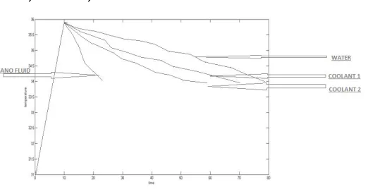
VIII. GRAPHICAL RESULT
A. Water takes 78 min to decreases temperature from 360 C to 340 C
B. Coolant 1 takes 70.8 min to decreases temperature from 360 C to 340 C
C. Coolant 2 takes 61.4 min to decreases temperature from 360 C to 340 C
D. Nano fluid takes 25.5 min to decreases temperature from 360 C to 340 C
IX. ADVANTAGES & DISADVANTAGES
A. Advantages
1) Heat transfer rate is high.
2) Density of nanofluid is high.
3) Thermal conductivity is high.
4) Temperature difference of inlet and outlet of radiator is high.
5) Preparation of mixture of nanofluid is easy.
6) It is cheaper and easily available.
X. CONCULSION
After doing the different simulation testing of coolants on the test rig the percentage of heat extraction of water + ethylene glue of base fluid coolant from radiator and that of 0.003 % Al2O3 + water + ethylene glue coolant the percentage of heat extraction from
radiator has increased by 41 % has we can see from results. A new manufacturing method would also be needed for mass production due to large time requirements of current methods Instead of using parallel setup a single tube with multiple passes could be beneficial this should increase the time that the fluid is exposed to the flowing air which would allow for more heat transfer. As mentioned before, the tube thickness could also be reduced which would allow for less time for the heat to conduct through the tube, and thus increase heat removal. Determining the key energy transport mechanism in Nanofluids. Future research should be focused on finding out the main parameters affecting the thermal conductivity of Nanofluids. The challenging point is to obtain the desirable nanoparticle product. The development of the nanoparticle production technique will be very helpful for the Nanofluid research. Nanofluids engineers would be prudent to pursue green designs by choosing nontoxic co biodegradable nanoparticles. So in last we can say that low cost, high volume production of stable green Nanofluids is one of the most challenging directions for future applied research.
REFERENCES
[1] Wear Check Africa “Effect of Temperature on Engine Lubricating Oil”, bulletin issue 43.
[2] Efeovbokhan, Vincent Enontiemonria, Ohiozua, Ohireme Nathaniel, 2013, “Comparison of the cooling effects of a locally formulated car radiator coolant with water and a commercial coolant”. The International Journal of Engineering and Science,01: 254-262.
[3] Prof. A. R. Khot, Prof. D.G. Thombare, Prof. S. P. Gaikwad and Prof. A. S. Adadande, 2007, “An Overview of Radiator Performance Evaluation and Testing” IOSR Journal of Mechanical and Civil Engineering (IOSR-JMCE):7-14.
[4] Prof. Chavan D.K. and Prof. Tasgaonkar G.S, 2013, “Study, analysis and design of automobile radiator (heat exchanger) Proposed with cad drawings and geometrical model of the fan”, International Journal of Mechanical and Production Engineering Research and Development (IJMPERD), 02:137-146.