CAD Modelling and Analysis of Round Ring Cloth
Peg Assembly Machine
Darshan D. Bapat1, Dr. S.K. Choudhary2, Ms. S.P. Bhorkar3
1
M. Tech Student, 2Professor, 3Assistant Professor, Department of Mechanical Engineering, K.D.K. College of Engineering, Nagpur, Maharashtra, India
Abstract: Cloth pegs are used for holding clothes especially when kept for drying. There are different types of cloth pegs available in the market, made from different materials like plastic, metal or wood. The two pieces of the cloth peg are held together either by a metal ring, U-pin, or spring. The plastic parts and the metal ring are manufactured separately and then assembled together. Assembly of the plastic parts and the ring is done manually. This is a very tedious and troublesome process. So, the researcher has designed a machine to reduce the human efforts and time.
Keywords: Cloth peg, Clothes, Plastic parts, Metal ring, Assembly machine
I. INTRODUCTION
A cloth peg is a fastener used to hang up clothes for drying, usually on a clothes line. They are made from plastic, metal or wood. A ring, spring or U-pin is inserted between the two parts of the cloth peg. The assembly of the cloth peg (two plastic pieces and ring) can be done manually by workers, or by semiautomatic or fully automatic machines.
Fig.1 Cloth peg assembly
II. NEED OF THE PROJECT
Inserting the ring in the two parts is very tedious and troublesome job for the workers. So, by developing the machine for the same will reduce the manual efforts of the workers which will ultimately benefit the company.
III. MACHINE DESCRIPTION
The major component of the machine is a grooved lever with a knob, mounted on a round up table. The round up table is mounted on a stand. The stand is made by welding two cross MS plates with a central rod. The dimensions of the plates are 250×45×10mm. Bolted holes of diameter 16mm are provided on the two cross plates for foundation and mounting of the whole setup on to a platform. The diameter of the central rod is 24mm. The round up table exactly fits in the central rod. The dimensions of the round up table are 350×50mm. At the two ends of the table two sockets having the shape of the cloth peg are made. The fulcrum of the lever is at the center of the round up table. The diameter of the fulcrum pin is 5mm. The dimensions of the cross-section of the lever are 13.4×6.7mm. A groove of 1mm thickness is made on one side of the lever to hold the ring. A knob is provided on the other side of the lever. The knob restricts the horizontal and vertical motion of the ring. A plier is used for stretching the ring for inserting it into the rectangular and circular grooves of the cloth peg.
IV. DESIGN CALCULATIONS
Fig.3 Lever
Fig.4 Free body Diagram of Forces acting on Lever
Where, F- Force to be applied on the knob to hold the ring in the groove P- Effort required to produce that force
R- Reaction at the fulcrum pin l1- Effort arm
l2- Load arm
1) Step 1: Force Analysis
Taking moments about the fulcrum, we get,
F×l2+P×l1=0
P×l1= -F×l2
P = -F× (l2/l1)
P = -1.917 N
R=F+P = (0.5*9.81) + (-1.917)
R= 2.988 N
2) Step 2: Design Of Lever Arm
Bending moment, Mb = P* (l1-d1)
Where, d1-Diameter of pin
We have d1=0.5 cm=0.005 m
Mb= -1.917*(0.353-0.005)
Mb= -0.667 N-m
Bending stress,σb = (1)
Where, I- Moment of Inertia
y- Distance from neutral axis to the outer-most fibre.
We have, I=bd3/12 and y = d/2
Where, b- Distance parallel to the neutral axis d - Distance perpendicular to the neutral axis
We have, σb = (2)
Equating equations (1) and (2)
Generally, d=2b
b=0.67 cm
Therefore, d=1.34 cm
Fig.5 Round Ring Cloth Peg Assembly Machine
Fig.6 Exploded view of the machine
VI. CAD MODEL OF DIFFERENT PARTS OF THE ASSEMBLY MACHINE
Fig.7 Stand
Fig.8 Round Table
Fig.9 Grooved Lever with knob
Fig.10 Bolt
Fig.11 Nut
VII. DESIGN ANALYSIS- ANSYS WORKBENCH-16.2
Mild Steel is selected for fabrication of the machine.
Fig.13 Boundary conditions of forces acting on the lever
Fig.14 Stress due to the forces acting on lever
[image:7.612.109.508.378.658.2]Fig.15 Deformation due to the forces acting on lever
Fig.16 Force reaction
TABLE I: Force Reaction
Time [s] Force Reaction (X) [N] Force Reaction (Y) [N] Force Reaction (Z) [N] Force Reaction (Total) [N]
Fig.17 Bending Moment acting on lever
Fig.19 Deformation due to the Bending Moment acting on lever
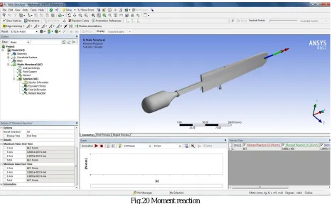
Fig.20 Moment reaction
TABLE III: Moment Reaction Time
[s]
Moment Reaction (X) [N·mm]
Moment Reaction (Y) [N·mm]
Moment Reaction (Z) [N·mm]
Moment Reaction (Total) [N·mm]
[image:9.612.74.541.372.659.2]VIII. CONCLUSION
As per the machine description and design, the CAD model of the Round Ring Cloth Peg Assembly Machine is prepared and its analysis is done using Ansys Workbench-16.2.
IX. ACKNOWLEDGMENT
I express my sincere gratitude to my guide Dr. S.K. Choudhary (Professor) and Co-Guide Ms. S.P. Bhorkar (Assistant Professor), Mechanical Engineering Department, K.D.K. College of Engineering, Nagpur for their valuable guidance, proper advice and moral support during the course of my work on this paper.
REFERENCES
[1] https://en.wikipedia.org/wiki/Clothespin
[2] VB Bhandari, “Design of Machine Elements”, Tata McGraw Hill Education Private Limited, New Delhi, India, Third Edition, 2012.
[3] R.S. Khurmi, J.K. Gupta, A Textbook Of Machine Design(S.I. Units), S.Chand Publications, Eurasia Publishing House(Pvt.) Ltd., Ram Nagar, New Delhi-110055, Fourteenth Edition, 2005.
[4] Er. R.K. Rajput, “Strength of Materials (SI Units), S.Chand & Company Ltd., Ram Nagar, New Delhi-110005, Fifth Revised Edition, 2012.
[5] R.S. Khurmi, J.K. Gupta, “Theory of Machines”, S.Chand Publications, Eurasia Publishing House (Pvt.) Ltd., Ram Nagar, New Delhi-110055, Fourteenth Revised Edition, 2007.
[6] SS Rattan, “Theory of Machines”, McGraw Hill Education (India) Private Limited, New Delhi, India, Fourth Edition, 2016. [7] J.S. Rao, R.V. Dukkipati, Mechanism and Machine Theory, Second Edition, New Age International (P) Limited, Publishers, 1998.
[8] S.K. Hajra Choudhury, A.K. Hajra Choudhury, Nirjhar Roy, Elements of Workshop Technology, Vol: 1 Manufacturing Processes, Media Promoters & Publishers Pvt. Ltd., Mumbai-400007, 14th edition, 2010.
[9] S.K. Hajra Choudhury, A.K. Hajra Choudhury, Nirjhar Roy, Elements of Workshop Technology, Vol: 2 Machine Tools, Media Promoters & Publishers Pvt. Ltd., Mumbai-400007, Thirteenth edition, 2014.