Samer Mutawe, Yahia M. Al-Smadi, Rajpal.S. Sodhi
Abstract— Four-bar path generation is used to calculate the mechanism parameters required to achieve or approximate a set of prescribed rigid-body path points. This work will discuss the path generation of four-bar mechanism with position tolerance variations due to joint running clearance. The tolerance variations study will be based on the standards of American National Standard Institute (ANSI). The new design constraint introduced in this paper will consider the joint tolerances and incorporate it into the displacement position matrix of the mechanism described in the conventional planar four-bar path generation models. The synthesized planar four-bar mechanism will produce tolerance limits for moving pivots and link length from which any mechanism can be synthesized to satisfy the prescribed path for the coupler point with its prescribed tolerance. The included example demonstrates the synthesis of a four-bar mechanism with joint tolerances. 1
Keywords—Path generation, joint tolerances, worst case tolerance, mechanism tolerance
I. INTRODUCTION
HE objective of four-bar path generation is to calculate the mechanism parameters required to achieve or approximate a set of prescribed rigid-body path points. This mechanism design objective is particularly useful when the rigid-body must achieve a specific displacement sequence for effective operation (e.g., specific tool paths and/or orientations for accurate fabrication operations). In Fig. 1 four prescribed rigid-body path points are defined by the coordinates of variables p, and α (path generation model input), and the
model outputs are the calculated coordinates of the fixed pivots a0 and b0 and moving pivot variables a1 and c1.
Planar mechanism synthesis with tolerances is a well-established field. These tolerances can be found in joints and linkages due to many factors such as manufacturing processes, loading and unloading of the mechanism which increases joint clearance after service period and causes impulsive forces. This paper investigates the effect of the required joint assembly tolerances on the synthesis of four-bar mechanism.
Samer Mutawe, Department of Mechanical Engineering, New Jersey Institute of Technology, Newark, NJ 07102-1982, U.S.A Yahia M. Al-Smadi, Special Practices Group, AECOM
New York, NY 10005, U.S.A
Rajpal S. Sodhi, Department of Mechanical Engineering, New Jersey Institute of Technology, Newark, NJ 07102-1982, U.S.A
Several methods and analyses have been used to include the error caused by joint clearances and link geometry tolerances in the mechanism synthesis. Graphical and mathematical approaches to investigate the efficiency of planar mechanisms to approximate the coupler poses considering the errors/tolerances in mechanism linkages were developed by [3] and [4]. Recent contributions performed by [5, 6 and 7] modeled the joint clearance as a massless virtual link (clearance link) and investigated the joint clearance effect on the mechanism performance to achieve the prescribed coupler curves/points. A method to predict the limits of the tolerance region by choosing the clearance value was also proposed by [7].
(a) (b)
Fig. 1 Prescribed rigid‐body poses (a) and calculated planar four-bar mechanism (b)
II. CONVENTIONAL PLANAR FOUR-BAR PATH GENERATION ANALYSIS
Equations (1) through (3) encompass a conventional planar four-bar path generation model presented by [1]
[ ]
( ) (
[ ]
) 21 1 0 1 1 0 0
T
j − j − −L1 =
D a a D a a , (1)
(
) (
)
21 1 0 1 1 0 2 0
T
j j −L =
⎡ ⎤ − ⎡ ⎤ −
⎣D ⎦b b ⎣D ⎦b b , (2)
1 1 1 1 1 1
1 1 1 1 1 1 1
cos sin cos sin
sin cos sin cos
0 0 1
j j jx x j y j
j j j jy x j y j
p p p
p p p
α α α α
α α α α
− − +
⎡ ⎤
⎢ ⎥
⎡ ⎤ = − −
⎣ ⎦ ⎢ ⎥
⎢ ⎥
⎣ ⎦
D
(3)
where j=1,2,3,4
These equations are “constant length” constraints and ensure the fixed length of links a0-a1 and b0-b1 throughout the
prescribed rigid-body displacements. Variables L1 and L2 in (1)
and (2) are the prescribed scalar lengths of links a0-a1 and b0 -b1, respectively.
α15
a0
b0
b1
a1
p1
X X
Y Y
α14
p5
p4 α13
p3 α12
p2
Planar Four-bar Path Generation Considering
Worst Case Joint Tolerances
Equation (3) is a rigid-body planar displacement matrix. From this conventional planar four-bar path generator model, 6 of the 10 unknown variables a0, a1 L1, b0, b1, and L2 are
calculated with two arbitrary choice of parameter (where
a0=[a0x, a0y, 1], a1=[a1x, a1y, 1], b0=[b0x, b0y, 1], and b1=[b1x,
b1y, 1].
III. TOLERANCE ANALYSIS.
This paper presents a technique of synthesizing planar four-bar path generation mechanism considering joint assembly tolerances. Insensitive analyses for optimal coupler point trajectory have been performed in mechanism synthesis, many goal functions have been formulated in an effort to define the linkages with a tolerance to approximate the desired coupler point path with tolerable accuracy. Investigations carried out by [20] and [21] on RRCC mechanism and multi-phase four-bar mechanism respectively show the mechanism motion synthesis with a prescribed tolerance for one position, while work presented in [8] shows optimal synthesis of crank-rocker linkages for path generation using orientation structural error of the fixed link. Several optimization algorithms, objective/goal functions and techniques on the shape of coupler curve and points have been presented in [15-18]. Al-Smadi et al [12] developed a nonlinear optimization to investigate four-bar with structural constraints. This research adds the consideration of the joint clearance tolerances to the synthesis of the four-bar mechanisms.
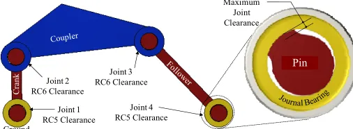
[image:2.612.50.303.559.652.2]The bilateral tolerance system selected for this study is in accordance with [13] which specify bilateral tolerance for pin-hole clearance fit, the main required tolerance for operation of four-bar mechanism was selected and presented herein. For any prescribed rigid-body path point to be achieved, the plus or minus deviation from the specified value would be the allowable tolerance limits. The variation required is the running clearance which is specified when mating parts are assembled, description of clearance fits can be found in [13]. The clearance adopted in this investigation will be medium running fits RC5 or RC6, as shown in Fig. 2. These fits are suitable for high running speed or heavy journal pressures.
Fig. 2 Joint running clearance required for planar four-bar mechanism
IV. WORST CASE TOLERANCE SYNTHESIS
Worst case tolerance model is widely used in the field of tolerance analysis. It measures tolerance stack-up of the mechanism in a simple form by summing the extreme hence absolute limits of the tolerances. The utilization of worst case tolerance will determine the allowances for coupler path point
p. this simplified tolerance model (5) is concluded in [25] which is based on the tolerance accumulation model (4) estimated by [23] and [24].
1 1 1
1 a b c
F
F
F
tol
tol
tol
a
b
c
∂
∂
∂
ΔΦ =
+
+
∂
∂
∂
(4)where ΔΦ1 is the worst case variation.
The predicted assembly tolerance is
1
n
Assembly i
i
T
δ
=
=
∑
(5)where n is number of parts considered in the tolerance analysis.
Worst case tolerance analysis converts the dimension with tolerance limits to a mean dimension with symmetrical tolerance limits. The stack-up tolerance is the summation of tolerance limit variation to the mean dimension for each part. Tolerance analysis example is given and explained in Section VI.
V. MODIFICATION OF POSES DISPLACEMENT MATRIX CONSIDERING TOLERANCE
Joint clearance tolerance would affect and produce a tolerance region for each coupler point to be positioned within. Research performed by [14] and [15] presented that the region of the moving pivot point in four-bar mechanism takes the shape of a rectangle with curved sides. If δx and δy
applied on each coupler point pose, then a tolerance region of a box shape would predict the limits with reasonable accuracy. [16, 17and 18] concluded that the tolerance region for coupler point positions is an ellipse shape. Using reliability analysis in mechanism synthesis, [19] formed a reliable region SR for
RCCC Mechanism. Russell and Sodhi [20] considered point tolerance for RRSS mechanism by considering δx and δy for
one pose only. This consideration would produce a tolerance region of a box shape if covariance is not calculated; this consideration still produces a tolerance region with reasonable accuracy. Similar consideration was performed by [21] in which a square tolerance region for one coupler point pose was suggested. Design sensitivity of an elliptical tolerance region versus square shape tolerance region was formulated by [22]. The tolerance region presented in this paper is considered as a square or a box shape. The work of [7], [20] and [21] for choosing the clearance value has been adopted. Therefore, (5) is defined to enumerate the maximum tolerance
Joint 1 RC5 Clearance
Joint 3 RC6 Clearance Joint 2
RC6 Clearance
Joint 4 RC5 Clearance
Crank Pin Maximum
Joint Clearance
Cr
an
k
Ground
value formed for each coupler path points 1 through 4. Fig. 3 shows the tolerance regions limited by ±δx and ±δy for coupler
[image:3.612.338.540.95.232.2]path point p.
Fig. 3 Tolerance region
The tolerance calculated from (5) will be used in the poses displacement matrix of the coupler point as shown in (7). Several cases of tolerance limits (i.e. 0δ, +δx, -δx, +δy, -δy ,
+δx and +δy, -δx and -δy, +δx and -δy , and -δx and +δy) are
investigated, moving pivots a1 , b1 and Links L1 and L2 are
synthesized for each case.
1 1 1 1 1 1
1 1 1 1 1 1 1
cos sin ( ) cos sin
sin cos ( ) sin cos
0 0 1
j j jx x x j y j
j j j jy y x j y j
p p p
p p p
α α δ α α
α α δ α α
− + − +
⎡ ⎤
⎢ ⎥
⎡ ⎤ = + − −
⎣ ⎦ ⎢ ⎥
⎢ ⎥
⎣ ⎦
D
where j=2,3,4
(6)
VI. EXAMPLE
Dimensions used in this example are in SI units. Path generation program can be used with prescribed values of
a0=(0, 0), b0=(0.5080, 0), and initial guesses of a1=( 0.2540,
0.3048), L1=0.3810, b1=(0.6096, 0.3048), and L2=0.5080.
Worst case tolerance model (δ) is calculated in Table 1 which later will be used in (6) and (7) to generate the area described in Section V. Table 2 shows the prescribed rigid body poses for planar four bar mechanism. Joint number and clearance are based on Fig. 2. Coupler path point can fall anywhere within that region. Therefore, nine tolerance cases has been discussed and investigated as shown in Table 3. Rigid-body path points 1 through 4 correspond to link a0-a1 rotation angles of θ1=45°,
70°, 120°, and 150° respectively. Therefore the displacement angles (δθ)1j for link a0-a1 are 25°,75° and 105° respectively.
TABLE1
WORST CASE TOLERANCES ANALYSIS
TABLE 2
PRESCRIBED RIGID-BODY POSES FOR PLANAR FOUR-BAR MECHANISM
p α
Pose 1 0.1479, 0.7330 30
Pose 2 0.0056, 0.8490 33.3966
Pose 3 -0.3981, 0.8081 30.8200
Pose 4 -0.6086, 0.6202 24.6646
Synthesized mechanisms which consist of the achieved moving pivot points a1 and b1 and link lengths L1 and L2
shown in Table 3 and prescribed values of a0, b0, were
constructed. All rigid-body path points achieved by the constructed mechanisms were investigated. They were found to be comparable with the prescribed path points and were within the calculated worst case tolerance range. One example (highlighted case shown in Table 3) is presented from this investigation, others can be done similarly. This case produces the longest link lengths L1 and L2. Table 4 includes
the rigid-body path points calculated after incorporating the parameters of the synthesized mechanism (a1x, a1y, L1, b1x, b1y,
L2) for the highlighted case.Rigid-body path points 1 through
4 correspond to crank angles of θ1= 29.5195°, 32.9152°,
[image:3.612.136.208.136.205.2]30.3376°, and 24.1722° respectively.
TABLE 3
CALCULATED COORDINATES OF THE MOVING PIVOT VARIABLES a1 AND b1 AND SCALAR LINK LENGTHS L1 AND L2
FOR NINE COMBINATION CASES OF WORST CASE TOLERANCE δ
TABLE 4
Rigid-body poses achieved by synthesized planar four-bar mechanism for chosen a1, b1from Table 3
p
Pose 1 5.8242, 28.8577 Pose 2 0.2129, 33.4278 Pose 3 -15.6935, 31.8129 Pose 4 -23.9877, 24.4063
q δx
δy
-δy -δx
p
Clerance Nominal Cente re d
Fit Size Dimension
Hole 0 0.001 0.5005 0.0005
Pin -0.0019 -0.0012 0.49845 0.00155
Hole 0 0.0016 0.5008 0.0008
Pin -0.0022 -0.0012 0.4983 0.0017
Hole 0 0.0016 0.5008 0.0008
Pin -0.0022 -0.0012 0.4983 0.0017
Hole 0 0.001 0.5005 0.0005
Pin -0.0019 -0.0012 0.49845 0.00155
1 RC5 0.5
Joint LL UL
0.0091
2 RC6 0.5
3 RC6 0.5
4 RC5 0.5
δ
i
δ ∑
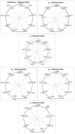
[image:3.612.316.560.442.676.2]The ranges of the achieved pivot variables for the given tolerance region are represented by the perimeter of the solid line in the plots of Fig. 4. The perimeter represents the value of these pivot variables for which, the rigid-body position tolerances will be within the prescribed limit. For the given tolerance, a least square best fit can be obtained for each of the variables. These best fit curves are represented in Fig. 4 using dashed-line format. Since only nine cases were analyzed here, the shape of the best fit curve is a nine-sided polynomial. But, a close examination of the data clearly indicates that for the entire square tolerance region (Fig. 3) the best fit curve will be a circle. The radius of this best fit curve represents the values of the pivot variable for which the given tolerances will always be met.
Fig. 4. Synthesized moving pivot points with tolerance limits, dotted line denotes the best fit curve for the achieved moving pivots pose
Fig. 5. Synthesized moving pivot points with tolerance limits, dotted line denotes the best fit curve for the achieved moving pivots pose
Fig. 6: Synthesized path generator
VII. DISCUSSION
When the pivots a1, b1, and b0 are collinear, the four-bar
mechanism reaches a “lock-up” or binding position. Modeling the prescribed rigid-body poses and concept mechanisms via CAD software could enable one to specify initial guesses for the unknown mechanism more judiciously than by arbitrary guessing. The mathematical analysis software MathCAD was used to codify and solve the formulated path with tolerance program. For future work, the tolerance modeling technique adopted by [26] will be considered.
VIII. CONCLUSIONS
Four-bar path generation is used to synthesize a mechanism which passes through or approximates prescribed rigid-body path points. This work discussed the path generation of four-bar mechanism with path points worst case tolerance which is due to joint clearance during assembly stage. ANSI standard for clearance fit tolerances was incorporated in the rigid-body displacement matrix. The synthesized mechanism approximate the prescribed rigid-body path points within the calculated path points tolerances.
REFERENCES
[1] C. H. Suh and C. W. Radcliffe, “Kinematics and Mechanism Design,” John Wiley and Sons, New York, (1978).
[2] G.N. Sandor and A.G.Erdman, “Advanced Mechanism Design Analysis and Synthesis,” Prentice-Hall, Englewood Cliffs, (1984).
0.3233 0.3230 0.3235 0.3233 0.3233 0.3231 0.3235 0.3230 0.3235 0.3232 0.3232 0.3232 0.3232 0.3233 0.3233 0.3233 0.3233 0.3233
Acheived a1x‐Tolerance Limits
0.3233 0.3232 0.3233 0.3230 0.3236 0.3229 0.3236 0.3236 0.3230 0.3232 0.3232 0.3232 0.3232 0.3232 0.3232 0.3232 0.3232 0.3232
a1y ‐Tolerance Limits
0.4572 0.4572 0.4572 0.4571 0.4573 0.4571 0.4573 0.4573 0.4571 0.4572 0.4572 0.4572 0.4572 0.4572 0.4572 0.4572 0.4572 0.4572
L1‐Tolerance Limits
0.8466 0.8464 0.8469 0.8467 0.8466 0.8464 0.8469 0.8464 0.8469 0.8466 0.8466 0.8466 0.8466 0.8467 0.8467 0.8467 0.8467 0.8467
b1x‐Tolerance Limits
0.5068 0.5067 0.5070 0.5064 0.5072 0.5063 0.5074 0.5071 0.5066 0.5068 0.5068 0.5068 0.5068 0.5069 0.5069 0.5069 0.5069 0.5069
b1y‐Tolerance Limits
0.6095 0.6094 0.6097 0.6094 0.6097 0.6093 0.6098 0.6096 0.6095 0.6095 0.6095 0.6095 0.6095 0.6095 0.6096 0.6096 0.6096 0.6096
L2‐Tolerance Limits
0 0.005 0.01 0.015 0.02 0.025 0.03
1 2 3 4
Sc al ar Erro r (i n )
Pose Number
[image:4.612.48.300.267.718.2][3] K. Lakshminarayana and G. Narayanamurthi, “ On the Analysis of the Effect of Tolerances in Linkages,” Journal of Mechanisms, Vol. 6, pp. 59-67 (1971).
[4] R.S. Hartenberg and J. Denavit, “Kinematic Syntheses of Linkages,” McGraw-Hill, New York (1964).
[5] M.J. Tsai and T.H. Lai, “Accuracy analysis of a multi-loop linkage with joint clearance,” Mechanism and Machine Theory, Vol. 43, pp. 1141-1157 (2008).
[6] M.J. Tsai and T.H. Lai, “Kinematic Sensitivity analysis of linkage with joint clearance on transmission quality,” Mechanism and Machine Theory, Vol. 39, pp. 1189-1206 (2004).
[7] K.L. Ting, J. Zhu and D. Watkins, “The effect of joint clearance on position and orientation deviation of linkages and manipulators,” Mechanism and Machine Theory, Vol. 35, pp. 391-401 (2000).
[8] H. Zhou and E. Cheung, “Optimal synthesis of crank-rocker linkages for path generation using the orientation structural error of the fixed link,” Mechanism and Machine Theory, Vol.365, pp. 973-982 (2001). [9] S.Erkaya and I. Uzmay, “Determining link parameters using genetic
algorithm in mechanisms with joint clearance,” Mechanism and Machine Theory, Vol. 44, pp. 222–234 (2009).
[10] M.A. Laribi, A. Mlika, L. Romdhane, S. Zeghloul, “A combined genetic algorithm–fuzzy logic method (GA–FL) in mechanisms synthesis,” Mechanism and Machine Theory, Vol. 39, pp. 717–735(2004).
[11] N. Diab, A. Smaili, “Optimum exact/approximate point synthesis of planar mechanisms,” Mechanism and Machine Theory Vol. 43, pp. 1610–1624 (2008).
[12] Y.M. Al-Smadi, K. Russell and R.S. Sodhi, “Four-Bar Path Generation with Structural Constraints,” CSME, Vol. 17(8), pp. 1059-1072 (2009). [13] ANSI B4.1-1967 (R1987) Standards, “American National Standard
Running and Sliding Fits”
[14] S.A. Kolhatkar and K.S. Yajnik, “The Effect of Play in the Joints of a Function-Generating Mechanism,” Journal of Mechanisms, Vol. 5, pp. 521-532 (1970).
[15] R.E. Garrett and A. S. Hall, “Effect of Tolerance and Clearance in Linkage Design,” ASME Journal of Engineering for Industry, pp.198-202, (1969).
[16] B.M. Imani and M. Pour “Tolerance analysis of flexible kinematic mechanism using DLM method,” Mechanism and Machine Theory, Vol. 44, pp. 445-456 (2009).
[17] J.W. Wittwer, K.W. Chase and L.L. Howell, “The direct linearization method applied to position error in kinematic linkages,” Mechanism and Machine Theory, Vol. 39, pp. 681-693 (2004).
[18] C.T. Brown, “Statistical models for position and profile variation in mechanical assemblies,” M.S. Thesis, Brigham Young University, Provo, Utah, 1995.
[19] Z. Shi, “Synthesis of Mechanical Error in Spatial Linkages Based on Reliability Concept,” Mechanism and Machine Theory, Vol. 32, No. 2, pp. 255-259 (1997).
[20] K. Russell and R.S. Sodhi, “Kinematic Synthesis of RRSS mechanisms for multi-phase motion generation with tolerances,” Mechanism and Machine Theory, Vol. 37, pp. 279-294 (2002)
[21] M.H. Mousa, K. Russell and R.S. Sodhi, “Multi-Phase Motion Generation Of Five-Bar Mechanisms With Prescribed Rigid-Body Tolerances,” Transaction of CSME, Vol. 30, Issue 4, pp. 459-472 (2006).
[22] S. Caro, F. Bennis and P. Wenger, “Tolerance Synthesis of Mechanisms: A Robust Design Approach,” ASME Journal of Mechanical Design, Vol. 127, pp. 86-94 (2005).
[23] Cox, N. D., 1986, "Volume 11: How to Perform Statistical Tolerance Analysis," American Society for Quality Control, Statistical Division. [24] Shapiro, S. S., Gross, A., 1981, "Statistical Modeling Techniques,"
Marcel Dekker.
[25] Chase, K. W., Gao, J. and Magleby, S. P., 1995a, "Generalized 2-D Tolerance Analysis of Mechanical Assemblies with Small Kinematic Adjustments," Journal of Design and Manufacturing, Vol. 5, No. 2, 1995.