Abstract— The UML (Unified Modeling Language) has its base in mainstream software engineering and it is often used informally by software designers. A limitation of UML is the lack of precise semantics, which makes its application to safety critical systems unsuitable. A safety critical system is one in which any loss or misinterpretation of data could lead to injury, loss of human lives and/or property. With the unrelenting use of UML in the software industry, there is a need to improve the informality of UML software models to remove ambiguity and inconsistency during verification and validation. To overcome this well-known limitation of UML, formal specification techniques (FSTs), which are mathematically tractable, are often used to represent these models. In this research, the authors refine transformation rules for aspects of an informally defined design in UML to one that is verifiable, i.e., a formal specification notation. The specification language used is the Z Notation. The rules are applied to UML class diagram operation signatures iteratively, to derive Z schema representations. This work was conducted as part of developing an unmanned aerial systems (UAS) project that complies with RTCA DO-178C specification.
Index Terms— Formal specification, Extended Bankus Naur Form, model transformation, safety critical systems
I. INTRODUCTION
HE Unified Modeling Language (UML) is an ISO standard for designing and conceptualizing graphical models of software systems [1]. Since its development by the Object Management Group (OMG) in the early 1990’s its use has increased in industry and academia. Graphical software models, such as UML models, possess simple designs and promote good software engineering practices. However, these models are not without limitation. Graphical software models are often imprecise and ambiguous. In addition, they are not directly analyzable by type checkers and proof tools. This makes it difficult to evaluate the integrity and correctness of its models; therefore, valid assertions cannot be made with regard to meeting user requirements.
Manuscript received January 19, 2016. This work was supported in part by the University of North Dakota, Faculty Research Seed Grant Program, May 2014.
Emanuel S. Grant, Ph.D. is an associate professor with the Department of Computer Science, University of North Dakota, North Dakota, USA phone: 701-777-4133; fax: 701-777-3330; (e-mail: [email protected].)
Tamaike Brown is a graduate research student with the Department of Computer Science, University of North Dakota, North Dakota, USA. (email: [email protected].)
Similar to other software development aids, UML has its limitations. These informal models have an advantage, such as expressiveness – which makes them easily conveyed to both technical and nontechnical stakeholders the objective of the system. However, UML lacks precise formal semantics, which results in its models being subject to multiple interpretations. This issue is aggravated by the use of natural language annotations – as a means of clarification and explanation of the modeling techniques adopted. Because of UML's inherent flexibility, developers are given much scope when designing models. This freedom enables the developer to describe system requirements based on the modeling technique they have adopted. However, problems arise when these models are circulated among the development team and each developer interprets the models in a different way – which could affect the latter stages of the software development life cycle (SDLC) [2]. This result in software maintenance being difficult as the UML models are often inconsistent with the source code and its significance is lost [3].
In some systems, the disadvantages of UML and the challenge of deriving precise models may not have a significant impact on the quality of software produced. In safety critical systems, any inadequacy could result in the loss of property or be harmful to life. The high cost during the implementation and early test phases are often times caused by errors at the specification and design phases [4]. Since UML is widely accepted, there is a need for methods to test the correctness of its models. This can be achieved with the use of formal specification techniques.
Formal Specification Techniques (FST) have been advocated as a supplementary approach to amend the informality of graphical software models [5, 6]. They promote the design of mathematically tractable systems through critical thinking and scientific reasoning. FSTs use a specification language, for instance Z notation, to describe the components of a system and their constraints [7]. Unlike graphical models, formal models can be analyzed directly by a proof tool – which checks for errors and inconsistencies. Critics of FSTs claim, they increase the cost of development, require highly trained experts, and are not used in real systems [8]. Yet, FST have been used in case studies that unveiled that facilitate a greater understanding of the requirements and their feasibility [9, 10]. Although the use of FSTs is sometimes controversial, their benefits to critical systems offset the disadvantages.
This work documents the transformation rules for UML
Towards Rigorous Transformation Rules for
Converting UML Operation Signatures to Z
Schema
Emanuel S. Grant,
Member, IAENG
, Tamaike Brown
class operation signature to an analyzable representation using formal specification techniques. Equally, the specific advancement that this works encourages is to provide a means by which these transformation rules can be automated. Automation is necessary because of the high volume involve in such work – manual interventions can be monotonous and inaccurate. Such process will reduce the introduction of human errors when applying transformation rules.
II. BACKGROUND A. Motivation
The University of North Dakota (UND) – UAS Risk Mitigation Project1 was awarded a contract to develop a proof-of-concept air truth system, which monitors the operation of UAS in the US National Airspace (NAS). Unmanned Aircraft Systems (UASs) have been in existence for many years. UAS is define as a system, whose components include the unmanned air vehicles (UAV) and corresponding hardware that do not involve an onboard human operator but instead maneuver autonomously or are remotely piloted, as well as the necessary software for operation of the UAV. UAS must be considered in a system context, which encompasses the command, control and communications systems, and personnel necessary to control the unmanned aircraft [11, 12]. Recently the use of UASs has experienced immense growth and plays a central role in scientific research, defense, and in certain industries [11, 13].
UAS technologies are categorized as safety critical systems. This is due to them being utilized in high-risk tasks that require thorough development methodologies to guarantee its integrity. A system that is defined as safety critical can have serious ramifications if a fault occurs. These implications include the risk of injury, loss of life, data, and property. Therefore, designing these systems requires: 1) thorough understanding of their requirements, 2) precise and unambiguous specifications, and 3) metrics to verify and validate the quality of software produced.
In order for safety critical aviation systems to be accepted by the United States Federal Aviation Administration (FAA) and other interested parties, it must adhere to standards such as the RTCA DO-178C [14]. The DO-178C is an airworthiness compliance standard, which governs the development and certification of avionic systems. DO-178C also addresses object-oriented development concepts and model-driven techniques.
B. Model-Driven Approach
The focus of Model Driven Engineering (MDE) is to transform, refine, and integrate models into the software development life cycle to support system design, evolution, and maintenance [15]. Models serve many purposes and their use varies from investors to investors. The purpose of modeling, from a developer’s standpoint, is to represent the proposed system by showing: 1) the flow of data between objects and individual components of the system as wells as
1 www.uasresearch.com/home.aspx
how they can interact with other software components, 2) Communication between internal entities and external components, and 3) how the system’s behaves to stimuli.
In model-driven engineering, the purposes and uses of graphical software models are multifaceted. They represent the structural design of the system, and the flow of data, and communication and control between the various systems and subsystems. Its use is not only suited for astute stakeholders but also non-technical stakeholders such as customers – to convey how their requirements are being met. Graphical software models are often imprecise and ambiguous. In addition, they are not directly analyzable by type checkers and proof tools. This makes it difficult to evaluate the integrity and correctness of its models; therefore, valid assertions cannot be made with regard to meeting user requirements.
C. Model Transformation
Model transformation and refinement is a process that lies at the heart of model driven engineering (MDE), where platform independent models (PIM) are translated into platform specific models (PSM) utilizing formal rules – additionally referred to as transformation rules [16]. The focus of MDE is to create and exploit domain models (that is, transform, refine, and integrate models), which are conceptual models into the software development life cycle to fortify system design, evolution and maintenance [16]. The benefits of MDE was recognized and embraced by many organizations, including the OMG. There are many categories of model transformations such as, text-to-model transformation, code transformation, and model-to-model transformation [15]. This work focuses on the latter; however, it will also highlight the process of deriving the platform independent models. The platform independent models will be the UML class diagrams and the platform specific models will be their representative Z schemata.
This research seeks to derive a set of manual transformation rules for a real world unmanned aerial system that are applicable to all problem domains. The outcome of this activity is to define a standard processes for yielding formal models from informal UML models for the problem domain. Manually transforming these models is tedious; and as such, it is prone to human errors. Consequently, if standard processes were established, it would prove advantageous to automate them in future work.
III. METHODOLOGY
This research is based on efforts of previous work done [9]. The work focused on formalizing UML software models of safety critical systems, and validating and verifying functional design for complex safety critical systems. In addition, rules for transforming UML graphical models to Z notation were defined. This research completes the transformation rule by defining a set of rules that must be followed for defining operations in a class. Fig. 1 shows an example of a class diagram base on the Unmanned Aircraft Systems (UAS) [9].
defined, it will be demonstrated by applying the rules to the operations shown in Fig. 1.
Fig. 1. Example of a UAS Class diagram
The UML model represents operation signature as textual, this work is more understandable if a textual meta-model representation is utilize. The scope of this meta-model is a class diagram. The textual description that is appropriate for this work is Extended Backus-Naur Form (EBNF) [17]. EBNF is a syntactic meta-language notation for expressing context-free grammars, in computer science. It often used where clear formal description and definition is required to describe the syntax of languages used in computing including computer programming languages [17]. The following EBNF grammar rules shown in Table 1 are adhered to when converting UML operations to EBNF.
The operations that the rules will be applied to are: •
•
•
A. Operation Transformation Rule
1) Defining Operation Basic Types Schemata
Declare all data types before schema definitions. Data types in Z are referred to as Basic Type or given sets of the specification. A feature of the Z notation is that it offers a calculus for building large specifications from smaller components [6] – and basic types facilitate this. The importance of basic types and given sets is that it allows one to categorize real world entities into sets. These sets are an essential part of Z schemas because they are used to represent objects and their respective attributes. In this work, basic types will be represented in capitalized letters so that they can be easily identified.
The developer must examine the attributes of each UML class to identify types that do not have an equivalent representation in Z. Presently; the Z Mathematical Toolkit only directly supports integers [33]. Therefore, other data types needs to be defined. Any string that is not of the type INTEGER (ℤ), a basic type will be created for it in the Z specification. The process of declaring basic types is not entirely automatable, because some data types will require manual intervention to ensure that they are representative of the parameters. However, the process of extracting the name of the data type and declaring them in the Z specification can
be automated.
TABLE 1. RULES FOR CONVERTING UML OPERATIONS TO EBNF <operation_signature> :: =
<return_type><operation_name>“(“<parameters>”)” <constraint> <return_type> :: = <z_type> |<user_defined_type>
<z_type> :: = ℤ|ℕ
<user_defined_type> :: = void | char | string | short | long | float | double | signed | unsigned | char_string
<char_string> :: = <letter><more_letter> <letter> :: = <upper_letter>|<lower_letter>
[image:3.595.306.546.79.410.2]<upper_letter> :: = A | B | C | D | E | F| G | H | I | J | K | L | M | N | O | P | Q | R | S | T | U | V | W | X | Y | Z
<lower_letter> :: = a | b | c | d | e | f | g | h | I | j | k | i | m | n| o | p| q | r | s | t | u | v | w | x | y| z
<more_letter> :: =<letter><more_letter> | _<more_letter> | <digit><more_letter> | <digit> | <letter>
<digit> :: = 0 | 1 | 2 | 3 | 4 | 5 | 6 | 7 | 8 | 9 <operation_name> :: = <char_string>
<parameters> :: = <parameter_pair> “,”<parameters> | <parameter_pair> <parameter_pair> :: = <return_type>< char_string>
<constraint> :: = < pre_condition><post_condition> | <pre_condition> | <post_condition>
<pre_condition> :: = PRE<const_string> <post_condition> :: = POST<const_string>
<const_string> :: = <char_string> | <special_char><const_string> | <special_char>
<special_char> :: = ∀ | ∃ | ∧ | ∨ | ¬ | ⊢ | ∃1 | ∅ | ∈ | ∉ | ∪ | ∩ | ⇒ | ⇔ | ≠ | ⇸ | ⤔ |⤀ | ⤗ | → |↣ |↠ |⤖ |⇻ |⤕ | λ | μ
If parameters do not have an associated data type, the name of the parameter will be declared and used as a Z basic type [10]. Examples of declaring an operation basic type schemata based on the class diagram and operations of Fig.
1 is: .
B. Define Parameter List Schemata
This step encompasses the description of the Z schema that will contain parameter of each operation. Each UML operation may contain zero or more parameters. For operations with no parameter this step is not executed, otherwise:
for instance . An example is given for the convert_heading operation in the Aircraft class diagram of Fig. 1, which contains one parameter. Their equivalent parameter type schema is shown in Fig. 2.
Fig. 2. An Example of a Parameter List Schemata C. Define Parameter Configuration Schemata
Operations in a class may contain parameters as an item of their execution. This step will be conducted only if an operation accepts parameters. The configuration schema includes all previously define parameter type. When creating these configuration schemata, each item in the parameter list of an operation is included as the definition of the parameter type. Each parameter will be identified by its name and corresponding basic type, thus mapping each parameter name to a Z data type or a basic type. These steps should be repeated for each operation that utilizes parameters in their operation implementation. The naming convention used for parameter configuration schemata is the name of the operation followed by the keyword ‘ ’. Currently, there is no automation of the pre- or post- conditions, comments will be utilized. An Example of defining parameter configuration schemata based on the
operation found in Fig. 1 class is depicted in Fig. 3.
Fig. 3. An Example of a Parameter Configuration Schemata
D. Define Operation Schemata
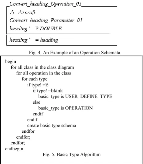
After defining the parameter configuration schemata, the operation schema is declared. It is mandatory for all methods to have a name. A method that does not have a name will result in compilation error. Making use of schema inclusion, an operation schema is defined by incorporating the associated parameter schema. Additionally, any other variables local to an operation are declared and where necessary constraints on variables or parameter values are, defined in the predicate part of the schemata. Operations with the same name may appear in different classes; therefore, a counter/index is utilized to identify each operation. The naming convention used for operation schemata is the name of the operation followed by the keyword ‘ ’. Key notational conventions are used in the operation schema definition, which indicates if the execution of a specific operation changes the state of the system. Δ means that there is a change in the state of the schema after the execution of an operation. An Example of defining operation schema based on the
operation is found in Fig. 4. E. Transformation Rules Algorithms
The algorithms of Fig. 5 illustrate the transformation rules that were described in the previous section. The algorithm
illustrates the steps corresponding to defining operation basic type schemata in Z. Each operation must be associated with a basic type in Z, if the basic type is not found in Z then one is define and is refer to as a user define type. Operations that have no associated type are assigned a basic type, that is, the operation name. All basic types are represented in block letter. This process is repeated until all basic types are defined.
Fig. 4. An Example of an Operation Schemata
Fig. 6 illustrates the process for defining one or more parameters found within an operation. A counter value is ascribed to a parameter name as an index. This index value differentiates each parameter in an operation, since more than one operation within a class may have the same parameter name. Any constraints relating to a parameter are also defined in the schema.
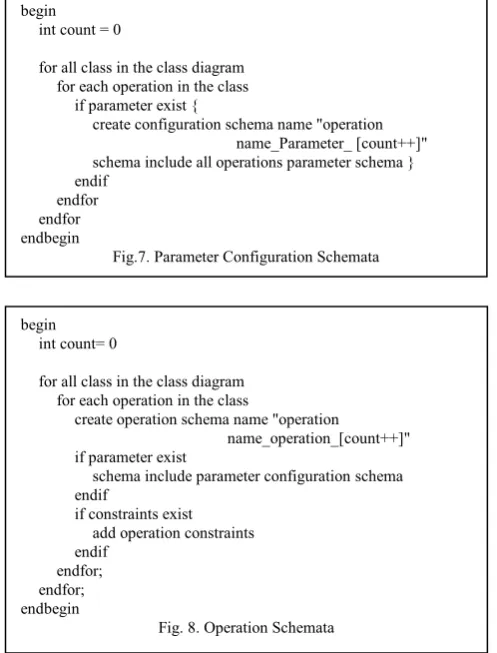
To define a parameter configuration schema, the following steps outlined in Fig. 7 must be followed. The schemata incorporate all previously define parameter schemata that are associated with the operation. An index is also attached to each schema name.
Fig. 8 depicts the process for defining operation schemata. An operation schema is defined by incorporating the
begin int count= 0
for all class in the class diagram for all operation in the class
for each parameter in the operation create schema name "parameter
name_Parameter_[count++]" create parameter schema
if constraints presents add constraints endif
endfor endfor; endfor; endbegin
Fig. 6. Parameter Algorithm begin
for all class in the class diagram for all operation in the class
for each type if type! =ℤ
if type! =blank
basic_type is USER_DEFINE_TYPE else
basic_type is OPERATION endif
endif
create basic type schema endfor
[image:4.595.305.538.154.422.2]endfor; endfor; endbegin
parameter configuration schemata with an index value join to the name of the schema. Any constraint that is placed on the operation is added also.
F. Application of Methodology
In this section, the transformations rules that were developed will be applied to Fig. 1.
These transformation rules include: Step 1: Defining basic types
Step 2: Defining Parameter Schemata
Step 3: Defining Parameter Configuration Schemata Step 4: Defining Operation Schemata
The collection of schemas in Fig 9 illustrates the formal representation of the class diagram in Fig. 1. These models were manually transformed and adhered to the rules outlined earlier in the methodology. The schemas of Fig. 10 were created manually and do verification of validation of them were conducted. Consequently, the correctness of the schemas is not assured in this report.
IV. CONCLUSION
In many software applications such as in the safety critical areas it is important to have correct and bug free software. Formal specification is one such approach to produce good quality, correct and error free software. The purpose of using notation like Z is to produce an accurate specification from initial client requirements. The notation has a restricted syntax so it is precise but still abstract enough so as not to constrain how a developer will go on to design application. This study supports the need for reliable development methodologies for safety critical systems and for avionic system development to comply with industry standard,
DO-178C specification. This work is an extension of previous work of Clachar and Grant that concentrated on formalizing, and verifying and validating UML software models for safety critical systems [9].
[DOUBLE]
Speed_Parameter_01 speed: ℙDOUBLE
∀s: speed ⦁ 0 ≤s ≤ 250 knots
Convert_to_internal_speed_Parameter_01 Speed_Parameter_01
Convert_to_Internal_Speed_Operation_01 ΔAircraft
Convert_to_Internal_Speed_Parameter_01 speed′, speed: ℙDOUBLE
speed′ = speed
Speed_Parameter_02 speed: ℙDOUBLE
∀s: speed ⦁ 0 ≤ s ≤ 250
[image:5.595.45.294.92.419.2]Convert_to_External_Speed_Operation_02 Speed_Parameter_02
Fig. 9. UAS Aircraft Z Schema
One of the principal concerns with amalgamating unmanned aircraft into national air space is their lack of ability to robustly sense and avoid other aircraft. Systems such as these must adhere to industry standard, for instance RTCA-DO178C, because they are classified as been safety critical. To ensure that catastrophic events (for example, loss life) do not occur, accuracy in safety critical systems is necessary.
Unified Modeling Language is the ISO standard for modeling systems. The class diagram is one type of UML model used to express systems requirements of stakeholders and to discover additional systems requirements. However, UML lacks precision when expressing design decisions. Textual descriptions are used to express characteristics of the system, which cannot be captured by UML. This further introduces another level of ambiguity in the models – since they are usually expresses in natural language. Hence, the begin
int count= 0
for all class in the class diagram for each operation in the class
create operation schema name "operation
name_operation_[count++]" if parameter exist
schema include parameter configuration schema endif
if constraints exist add operation constraints endif
endfor; endfor; endbegin
Fig. 8. Operation Schemata begin
int count = 0
for all class in the class diagram for each operation in the class
if parameter exist {
create configuration schema name "operation name_Parameter_ [count++]" schema include all operations parameter schema } endif
endfor endfor endbegin
[image:5.595.318.518.116.563.2]need for a meta- model (EBNF) that would bring more formatting and understanding to the work conducted in this research. One method that is used to remove ambiguity in models is to transform UML models into an analyzable representation using formal specification techniques (FSTs). FSTs are based on mathematical logics, which makes use of first order logics and set notation. Adopting such approach to system development plays an important role in safety critical system.
FSTs have been in existence prior to the beginning of UML. However, unlike UML it does not have a high level of simplicity that makes its models easily communicated to stakeholders. Currently, the formalization process is conducted manually. To make research on FSTs more worthy, some degree of automation is imperative. Therefore, conducting a case study in the area of automated tools for FSTs in safety critical systems will be beneficial in enlightening researchers on the complexity, advantages, and possible use of such software.
This case study supports research that identify the benefits of the application of formal methods to industries such as Formal specification of an oscilloscope (Tektronix) and Formal methods in safety-critical railway systems. In the former study, the researcher adopted formal methods to gain insight into system architecture. In the latter work, the B formal method was used in the development of platform screen door controllers. Both investigations concluded that the application of formal specification appears to be precise, efficient, and well suited to address projects requiring high level of safety [18, 19].
The value of this research contribution may be extended to automotive control systems (for example, factory, marine, space exploration, robotics, and other specialist areas) where formalism is a necessity. The use of formal methods is an effective means to improve complex systems reliability and quality. Benzadri et. al. adopted a formal method that utilized modeling interactions between cloud services and customers. The researchers combined Cloud customers’ bigraph and Cloud services bigraph to specify formally Cloud services structure. This study is applicable to formalizing Cloud computing concepts and to overcome one of Cloud computing main obstacles, specifically bugs in large scale Distributed Systems – “one of the difficult issues in Cloud computing is removing errors in these very large scale distributes systems” [20, 21]. The main issue that still needs to be addressed is the crucial absence of an appropriate model for Cloud computing. This research might be able to support major Cloud computing concepts specification and allow formal modeling of high-level services provided over Cloud computing architecture.
REFERENCES
[1] ISO/IEC 19501, Information Technology - Open Distributed Processing, Unified Modeling Language (UML) Version 1.4.2 (2005).
[2] Sommerville, I, Software Engineering 9th Ed. Addison Wesley, Boston, Massachusetts, 2010..
[3] Berkenkotter, K., “Using UML 2.0 in Real-Time Development: A Critical Review” in Proc SVERTS Workshop, 2003.
[4] Potter, B., Sinclair J.: An Introduction to Formal Specification and Z. 2nd ed. Prentice Hall (1996).
[5] France, R. B., Evans, A., Lano, K., Rumpe, B.: The UML as a Formal Modeling Notation. In Computer Standards & Interfaces, vol 19, issue 7, 325--334 (1998).
[6] Hall, A.: Using Z as a Specification Calculus for Object-Oriented Systems. In Proc of the 3rd International Symposium of VDM Europe on VDM and Z - Formal Methods in Software Development, 290--318 (1990).
[7] ISO/IEC 13568, Information Technology: Z Formal Specification Notation - Syntax, Type System and Semantics. 1st. ed. ISO/IEC 2002)
[8] Hall, A.: Seven myths of formal methods, Software, IEEE , vol.7, no.5, 11--19, (1990).
[9] Clachar, S., Grant E. A Case Study in Formalizing UML Software Models of safety Critical Systems. Annual International Conference on Software Engineering. Phuket, Thailand (2010).
[10] France, R.B., Bruel, J., Larrondo-Petrie, M.M.: An Integrated Object-Oriented and Formal Modeling Environment. In Proceedings of JOOP. 25--34. (1997).
[11] U.S. Dept. of Defense: FY2009-2034: Unmanned Systems Integrated Roadmap, 2009.
[12] Gupta, S.G., Ghonge, M.M., Jawandhiya, P.M.: Review of Unmanned Aircraft Systems (UAS). International Journal of Advanced Research in Computer Science Engineering & Technology (IJARCET), Volume 2, Issue 4, April 2013.
[13] Filter Implementation for Unmanned Aerial Vehicles Navigation Developed with a Graduate Course. Institute of ASE at Faculty of EE (2005) St. Cyril and Methodius University, MK-1000, Skopje, Republic of Macedonia.
[14] RTCA, Inc, EUROCAE: DO-178B, Software Considerations in Airborne Systems and Equipment. SC-167 (1992) RTCA, Washington DC, USA.
[15] Mens, T., Van Gorp, P.: A Taxonomy of Model Transformation, Electronic Notes in Theoretical Computer Science, vol 152, In Proceedings of the International Workshop on Graph and Model Transformation (GraMoT 2005), 125-142, ISSN 1571-0661 (2006). [16] Sendall, S.; Kozaczynski, W., “Model Ttransformation: The Heart
and Soul of Model-Driven Software Development Software”, IEEE , vol.20, no.5, pp. 42-45, Sept.-Oct. 2003.
[17] [31] ISO/IEC 14977:1996 International Standard. Information Technology – Syntactic metalanguage – Extended BNF.
[18] Delisie, N., Garlan, D.: A Formal Specification of an Oscilloscope. IEE Software, Volume 7, Number 5, September 1990.
[19] Leconte, T., Servat, T., Pouzancre, G.: Formal Methods in Safety-Critical Railway Systems. ClearSy, Aix en Provence, France. [20] Armbrust, M., Fox, A., Grith, R., Joseph, A.D., Katz., Konwinski, A.,
Lee, G., Patterson, D.A., Rabkin, A., Stoica, I., Zaharia, M.: Above the clouds: A Berkeley View of Cloud Computing. Technical Report UCB/EECS-2009-28, EECS Department, University of California, Berkeley (2009).