Air Conditioning Control System Learning
Sensory Scale Based on Reinforcement Learning
Yohei Yamaguchi, Noritaka Shigei, Hiromi Miyajima
Abstract—This study proposes the air conditioner (AC) control system based on users’ sensations. The purpose is to realize the control system that improves low-performance ACs in terms of energy efficiency and comfortableness performance. The system consists of wireless sensor nodes and user nodes such as PCs and smartphones, and it is applicable to already installed ACs. The users enter their sensation such ascold,good, a little hotandvery hotthrough the user node, and the system determines the appropriate control according to the users’ sensations. The appropriate control policy is determined based on Q-Learning, which is a reinforcement learning method. For multiple users, several methods for integrating users’ sensations are presented. These makes our proposed system applicable to a large number of users. Further, in order to reduce the energy consumption and the number of users’ inputs, several types of reward functions are presented. In the simulation, four types of methods are evaluated in terms of the time needed for providing a comfortable environment and the energy consumption. We clarify the effective methods among them.
Index Terms—air conditioning, reinforcement learning, wire-less sensor network, sensory scale, integration of sensations
I. INTRODUCTION
In our modern life, the air conditioning system is an essential system. The system needs to be energy efficient and to provide a comfortable room temperature environment[1]. Its state-of-the-art systems, which are generally expensive, equip many high-precision sensors and can achieve high en-ergy efficiency and high comfortableness. Due to budgetary constraints, many facilities often have to use old systems or introduce systems with low introducing cost, which are of low-performance in the control ability. However, such systems are of low energy efficiency and cannot always reasonably provide a comfortable environment. Further, for a large room with many workers, the difference between the ideal performance and the actual one would be large. Because the low-performance systems generally do not equip sufficient number of sensors for sensing the whole room.
Thanks to the recent advances in wireless sensor network (WSN) technologies, WSNs have been effectively employed in various fields such as industry[2] and home automation[3]. The sensing capability of WSN can be utilized for improving the old or low-performance systems. Since wireless sensor devices become much cheaper year by year, it is also a realistic approach. Further, recent years, mobile devices such as tablet PCs and smartphones are to be found everywhere. By incorporating them into WSN system, a powerful system can be realized with a reasonable cost.
Manuscript received December 29, 2014; revised January 16, 2015. This work was supported by JSPS KAKENHI Grant Number 26330108. Y. Yamaguchi, N. Shigei and H. Miyajima are with the Graduate School of Science and Engineering, Kagoshima University, 1-21-40 Korimoto, Kagoshima, Japan, e-mail: [email protected], [email protected], [email protected]
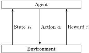
For realizing intelligent control systems, reinforcement learning (RL) is a promising technique. RL does not need any teacher signal and it can obtain an appropriate behavior pattern by trial and error according to rewards given from the environment[7], [6]. Therefore, RL can be applied to prob-lems with unknown environment. In RL, in order to obtain an appropriate behavior pattern (policy) for the environment defined by the target problem, the agent repeats trial and error and updates its policy according to some reward obtained from the environment (see Fig.4). RLs have been applied to room environment conditioning. In [4], for air conditioning, PI controller has been combined with RL. The purpose of the control is the minimization of the control error. In [5], for lighting system, an intelligent control system has been proposed by actor-critic algorithm, which is one of RLs. The system controls the lighting system according to the presented user’s sensation such as brighter and darker. This approach is gentle to humans and attractive in the case where the control has to be determined according to many users.
In this study, we propose the AC control system based on users’ sensations. The purpose is to realize the control system that improves the low-performance AC in terms of energy efficiency and comfortableness. The system consists of wireless sensor nodes and user nodes such as PCs and smartphones, and it is applicable to already installed ACs. The users enter their sensation such as cold, good, a little hot and very hot through the user node, and the system determines the appropriate control according to the users’ sensations. The appropriate control policy is determined based on Q-Learning, which is one of RLs. For multiple users, several methods for integrating users’ sensations are presented. Further, in order to reduce the energy consumption and the number of users’ inputs, several types of reward functions are presented. In the simulation, four types of RL methods are evaluated in terms of the time needed for providing a comfortable environment and the energy consumption. We clarify the effective methods among them.
II. MODEL OFROOMENVIRONMENT
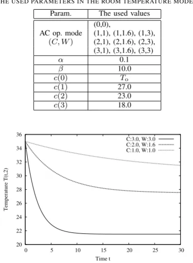
In this section, a model of the temperature in a room environment with an air conditioner is described. LetC >0 andW >0be the cooling strength of the air conditioner and the fan speed, respectively. LetT(t, d)be the air temperature at time t and at distance d away from the air conditioner. Then, we define the relation ofT(t, d),C,W andd, based on the RC electric circuit model. The temperatureT(t, d)is defined as follows:
T(t, d) =T(t−1, d) +Tdrp· (
1−exp
(
−1
τ(d, C, W)
)) ,
(1)
TABLE I
THE USED PARAMETERS IN THE ROOM TEMPERATURE MODEL. Param. The used values
(0,0),
AC op. mode (1,1), (1,1.6), (1,3),
(C, W) (2,1), (2,1.6), (2,3), (3,1), (3,1.6), (3,3)
α 0.1
β 10.0
c(0) To
c(1) 27.0
c(2) 23.0
c(3) 18.0
20 22 24 26 28 30 32 34 36
0 5 10 15 20 25 30
Temperature T(t,2)
Time t
[image:2.595.69.268.64.335.2]C:3.0, W:3.0 C:2.0, W:1.6 C:1.0, W:1.0
Fig. 1. Changes in the room temperature when changingCandW.
τ(d, C, W) = min
( β·d C·W, β·d
)
(3)
where To is the outer air temperature, α and β are
con-stant numbers, and c(C) is a decreasing function with C. The factor Tdrp determines whether the temperature T(t, d)
raises or falls. IfTdrp is positive, the temperature increases.
Otherwise, it decreases. The coefficient α is the influence rate of To and0 ≤α≤1.0. The function c(C)determines
the lower (upper) limit of the temperature in the case of a rise (fall) in temperature. The parameters used in this paper is shown in Table I.
Fig.1 shows the changes of the temperatureT(t, d)ford= 2and the differentCandW. In the figure, it is observed that, asCandW increase, the convergence temperature decreases. Fig.1 shows the changes of the temperatureT(t, d)forC= 3,W = 2and the different d.
In the figure, it is observed that, the convergence temper-atures are same but the convergence speed becomes faster with the distance d.
III. AIRCONDITIONINGCONTROLSYSTEM BASED ON SENSUOUSINSTRUCTION
A. System Configuration
In this section, we explain our air conditioning system based on sensuous instruction. Our system consists of an air conditioner (AC), two types of sensor devices, user nodes such as personal computer (PC), tablet and smartphone (see Fig.3). The AC equips an infrared remote controller. The first type of sensor device is installed around the receiver of the AC so as to receive the infrared signal from the remote controller. The sensor device sniffs the infrared signal and monitors the operation mode of the AC. The sensed informa-tion on the operainforma-tion mode is sent to the server program run
26 27 28 29 30 31 32 33 34 35
0 5 10 15 20 25 30
Temperature T(t,d)
Time t
C:2, W:3, d:1 C:2, W:3, d:1 C:2, W:3, d:3
Fig. 2. Changes in the room temperature when changingd
.
Air Conditionar
Sensor device
Sensing temperature
Wireless communication *IR remote control function *Sensing opeation mode
User node User interface
[image:2.595.340.508.238.411.2]Sensor device
Fig. 3. Air conditioning control system.
on one of the user nodes by wireless communication. Further, the sensor device also equips the infrared LED, which is used for controlling the AC according to the command from the server program. The second type of the sensor device is installed around the users and each sensor monitors the air temperature around the user. The sensed temperature is also sent to the server program by wireless communication. The primary role of the user nodes is the interface between the user and the system. Through the user interface application run on the node, the user enters his/her sensation such as
cold,good,a little hot,very hot. The entered sensation is also sent to the server program. The server program is run on one of the user nodes. The program collects the information from the sensor groups and the user nodes, calculates the action for control according to the collected information, and controls the AC by emitting the infrared signal from the sensor device.
B. Q-Learning for AC Control Based on User’s Sensation
Environment Agent
Fig. 4. The concept of reinforcement learning.
applicable to problems with unknown environments. Profit Sharing (PS)[7] and Q-learning are well-known reinforce-ment learning methods. Compared with PS, it is know that, Q-learning has a higher ability to obtain an optimal policy.
In this subsection, we present the basic form of our Q-learning algorithm for controlling our AC system. In section IV, some key components in the basic form are customized, and four types of the algorithm are presented. Let N be the number of users. Let S be the set of states, in which each member corresponds to the user sensation.
S is a key component defined in the next section. Further, the determination of the state involves the integration of
N users’ sensations, which is also described in the next section. Let Abe the set of actions, in which each member corresponds to the AC operation mode (C, W), that is,
A = {(0,0),(C, W)|C ∈ {1,2,3}, W ∈ {1,1.6,3}}. Let
Q(s, a) be the Q-value of the pair of state s and action a, which indicates how much worth is the actionaat the state
s. As the learning progresses, the Q-value of an appropriate pair of state and action increases. At each state s, the action with higher Q-value is taken with a higher probability compared with other actions. We assume that the goal of air conditioning is to keep the satisfaction (good) of two-thirds users forTsat time steps. The algorithm is given as follows:
ALGORITHM Q-Learning for AC Control Initialization:
Letl be the current epoch number, and setl←0. Lett be the current time, and sett←0.
For alls∈S anda∈A,Q(s, a)←0.
Step 1 (State observation): Determine the current states0
according to the N user inputs.
Step 2 (Taking action): For each action a ∈ A, calculate the probability π(st, a)as follows:
π(st, a) =
exp(Q(st, at)/Tb) ∑
a′∈Aexp(Q(st, a′)/Tb)
(4)
Tb=Tb0· (
Tb1 Tb0
) l
Lmax
(5)
where Lmax is the number of maximum epochs, Tb is the
temperature for Boltzmann selection, and Tinit andTfin are
maximum and minimum temperatures Tb respectively.
Probabilistically take an action at ∈ A according to the
probabilitiesπ(st, a)(a∈A).
Step 3 (Reward acquisition and state observation):Letrt
be the acquired reward, which is a key component described in section IV. Determine the next statest+1 according toN
users’ inputs.
Step 4 (Updating Q value):
Q(st, at)←Q(st, at) +α·δt, (6)
where
δt=rt+γ·max
a∈AQ(st+1, a)−Q(st, at), (7)
αis the learning rate andγis a constant such that0≤γ≤1.
Step 5 (Judgment of goal achievement): If the goal is reached, that is, two-thirdsN users feelgoodfor consecutive
Tsat time steps, go to the next step. Otherwise, sett←t+ 1
and go to Step 2.
Step 6 (Judgment of termination):Set l ← l+ 1. If l =
Lmax, then terminate the algorithm. Otherwise, for the next
epoch, setT(0, d),To and the users’ sensation scales, which
depend on the environment. Sett←0 and go to Step 1. □ In section IV, the set of statesS, the integration of users’ sensations and the rewardrtare described in detail.
IV. INTEGRATION OFUSERS’ SENSATIONS ANDREWARD FUNCTION
In this section, we explain the set of states S, the inte-gration of users’ sensations and how to give the reward. The naive design of the state set is to represent all the possible combinations of the users’ sensations. However, this design needs the number of states that is proportional to the exponential of the number of usersN. AsN increases, the memory size needed by the naive design exponentially increases. Therefore, in this section, we presents three types of integration methods of users’ sensations. Further, how to give the reward is an important issue in reinforcement learning. Firstly, we present the reward function using not only the users’ sensations and but also the changes of room temperature obtained from the sensor. Then, we also present the reward function using only the users’ sensations, which does not need sensing the room temperature.
A. Naive Design of State Set
The state is coded as a tuple of N + 1 elements (s(1), s(2),· · · , s(N), s∆T). Each ofN elements corresponds to a user sensation, that is, for each n ∈ {1,2,· · · , N},
s(n) ∈ S, where S = {cold, good, a little hot, very
hot} is the set of user’s sensations. The rest one element
s∆T represents the state of temperature change, which is
determined according to the sensing data of a sensor node. Let ∆T = T(t, dsn)−T(t−1, dsn) be the change of the
temperature, where dsn is the distance of the sensor node
from AC. The elements∆T is defined as follows:
s∆T=
Down ; ∆T <−0.5
U nchanged ; |∆T| ≤0.5
U p ; ∆T >0.5.
(8)
Then, the number of states is|S|N·3 = 4N·3.
B. Integration of Users’ Sensations
Let us consider to integrate the users’ sensations into the collective sensation. We present three types of sensation in-tegration (SI) methods: SI based on Majority Vote (SI-MV), SI based on Averaging (SI-A) and SI based on Likelihood (SI-L).
The first method, SI-MV, integrates N users’ sensations into the collective sensationsc as follows:
sc= argmax
s∈S
where U(s, t) is the number of users whose sensations are
s at time t, S ={cold, good,a little hot, very hot} is the set of user’s sensations, and if U(s, t)s for plural sensations
s tie in majority vote then the function argmax returns the sensation in order of cold, good and a little hot. The state set for SI-MV is S = {(sc, s∆T)|sc ∈ S, s∆T ∈
{Down, U nchanged, U p}}. Then, the number of states for SI-MV is |S| ·3 = 12for any number N.
The second method, SI-A, represents each user sensation as a scalar value, calculates the average of the scalar values and returns the integrated one from 12 possible sensations whose segmentation is finer than the one of the original sensation with 4 segments. The mapping from the user sensation s(n) ∈ S to a scalar value v(s(n)) ∈ V is as
follows:
v(s(n)) =
0 ; s(n)=cold
1.0 ; s(n)=good
2.0 ; s(n)=a little hot
3.0 ; s(n)=very hot,
(10)
where V = {0,1.0,2.0,3.0}. The averaging value v¯ =
1 N
∑N
n=1v(s
(n)) is mapped to the collective valuevc ∈ Vc
as follows:
vc= argmax
v∈Vc |
v−v¯|, (11)
where Vc = {0.25, 0.5, 0.75, 1.0, 1.25, 1.5, 1.75, 2.0,
2.25,2.5, 2.75, 3.0}. The state set for SI-MV is S = {(vc, s∆T)|vc ∈ Vc, s∆T ∈ {Down, U nchanged, U p}}.
Then, the number of states for SI-A is|Vc| ·3 = 36 for any N.
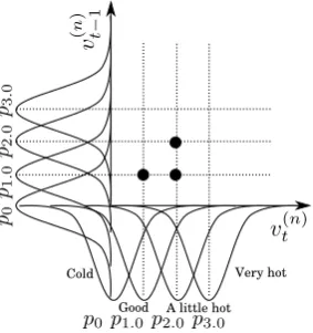
The last method, SI-L, determines the current state based on the likelihood on the users’ sensations at timetandt−1. Likewise SI-A, SI-L represents the user sensation as a scalar value. Unlike SI-MV and SI-A, SI-L takes into account not only the user sensations at the current timetbut also the one at the previous time t−1. With this feature, SI-L does not use the information on the temperature change.
Let s(tn) andst(−n)1 be the n-th user’s sensations at timet
andt−1, respectively. Let v(tn) and v(t−n)1 be the converted scalar values of then-th user’s sensations at timetandt−1, respectively. The conversion is done by using Eq.(10). Then, the set of states isS={(vcurc , vprevc )|vccur, vcprev∈ V}, where vcurc and vcprev correspond to the collective values at timet
and t−1, respectively. The number of states for SI-L is |V|2= 16.
In the following, the determination of the current state for SI-L is described in detail. The probability density function
pvof the user sensation corresponding to the converted scalar
valuev∈ V is defined as follows:
pv(v(n)) =
1 √
2πσexp (
−(v(n)−v) 2σ2
)
, (12)
whereσ2 = 1 is the variance of the distribution. Given the N users’ sensation scalar values at time t and t−1, v(1)t ,
vt(2),· · ·,vt(N),vt(1)−1,v(2)t−1,· · ·,v(t−N1), then the likelihood of each state(vcur, vprev)∈S is calculated as follows:
L(vt(1),· · ·, v(tN), vt(1)−1,· · · , vt(−N1);vcur;vprev) =
N ∏
n=1
pvcur(v (n)
t )·pvprev(v
(n)
t−1). (13)
Cold
Good A little hot Very hot
Fig. 5. The probability density function arrangement for SI-L and an input example for 3 users.
The collective state sc = (vc
cur, vcprev)∈S is calculated as
follows:
sc=
argmax
(vcur,vprev)∈S
L(vt(1),· · · , v (N)
t , v
(1) t−1,· · ·, v
(N)
t−1;vcur;vprev).
(14)
C. Reward Function
We consider three types of reward functions. The functions take into account the following issues.
• RL>0: Reward for goal achievement.
• RS>0: Reward for keeping a good control.
• RN < 0: Penalty on the degradation on the users’
sensations.
• RC<0,ρ·RL,ρ·RS: Penalty for excess cooling, which
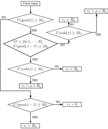
means dissipation of energy, where0.0< ρ <1.0. The first type is Excess-Cooling-Unaware Reward Func-tion (ECU-RF). ECU-RF does not care about any excess cooling, that is, it does not useRC<0,ρ·RL nor ρ·RS.
Fig.6 shows how ECU-RF determines the reward rt, where U(s, t) is the number of users whose sensations are s∈ S
at timet, andMS=⌈23N⌉is the minimum number of users
to be satisfied.
The second type is Soft-Penalty-for-excess-Cooling Re-ward Function (SPC-RF). SPC-RF reduces the reRe-ward with the reduction rateρwhen the AC control is excess cooling. Fig.7 shows how SPC-RF determines the rewardrt, where MCis the number of users that are not allowed to feelcold.
The third type is Hard-Penalty-for-excess-Cooling Reward Function (HPC-RF). HPC-RF gives a negative reward RC
when the AC control is excess cooling. Fig.8 shows how HPC-RF determines the rewardrt.
V. NUMERICALSIMULATION
A. Simulation Setting
The virtual users used in the simulation have sensory scales as shown in Fig.9, where thresholds θ1, θ2 and θ3
represent the boundaries between cold and good, between
[image:4.595.356.498.53.204.2]Users input
YES
NO NO
NO YES
[image:5.595.347.505.50.281.2]YES
Fig. 6. The definition of Excess-Cooling-Unaware Reward Function (ECU-RF).
Users input
NO
NO
NO
NO
YES YES YES YES
YES NO
Fig. 7. The definition of Soft-Penalty-for-excess-Cooling Reward Function (SPC-RF).
users is arranged at each distance d ∈ {1,2,3}. At each epoch, set randomly the initial room temperature T(0, d), the outer air temperature To, and the target temperature and
the thresholdsθ1,θ2 andθ3 for each user.
We evaluate the four types of methods as shown in Table III. The used parameters for the evaluated methods are summarized in Table IV. These parameters are determined by preliminary simulations.
B. Simulation Result
We evaluate four types of methods (w/o, SPC), (MV, ECU), (A, HPC) and (L, HPC) in terms of the time needed for reaching goal and the averaging amount of cold air needed for reaching goal. The simulation results are shown in Figs. 10 and 11.
NO
NO
NO NO
YES
YES
YES
[image:5.595.90.249.51.251.2]YES Users input
Fig. 8. The definition of Hard-Penalty-for-excess-Cooling Reward Function (HPC-RF).
Cold Good A little hot Very hot
-1.0 0.0 1.0 2.5
The difference between the target temperature
Fig. 9. Sensory scale of virtual user.
In Fig.10, a smaller time means that the users may enter their sensation fewer times. Although all the methods need a large time at the first epoch, the needed time quickly converges to reasonable values. For the needed time, the method (L, HPC) is the best among all the methods. The methods (A, HPC) or (w/o, SPC) are the second best. How-ever, the method (w/o, SPC) is forN = 3 users. Therefore, it is notable that the methods (L, HPC) and (A, HPC)
TABLE II SIMULATION CONDITIONS.
Item Used values
User’s dist. from ACd 1, 2, 3 Target temperature 26.0±0.5 ◦C
Initial temperatureT(0, d) Same as outer air temperature Outer air temperatureTo 30∼35◦C
θ1 −1.0±0.3 ◦C
θ2 1.0±0.3 ◦C
θ3 2.2±0.3 ◦C
Number of users to be satisfiedMS ⌈23N⌉
Maximum number of epochsLmax 500
Duration of satisfaction state 10 minutes
TABLE III EVALUATED METHODS.
Name w/oSensation IntegrationMV A L ECUReward FunctionSPC HPC
(w/o, SPC) ◦ ◦
(MV, ECU) ◦ ◦
(A, HPC) ◦ ◦
[image:5.595.66.272.294.538.2] [image:5.595.348.504.328.376.2]TABLE IV
PARAMETERS FOR EACH METHOD.
Item (w/o,SPC) (MV, ECU) (A, HPC) (L, HPC)
Number of usersN 3 12 12 12
Discount rateγ 0.7 0.7 0.9 0.9
Learning rateα 0.2 0.2 0.5 0.3
Max. temp. in B.S.Tb0 60 60 5.0 3.0
Min. temp. in B.S.Tb1 50 50 0.3 0.3
Reduction rateρ 0.3 1.0 – –
MS 1 8 8 8
MC 1 – 5 5
RL 400 400 400 40
RS 30 30 3 3
RN −400 −400 −400 −20
RC – – – −10
for N = 12 users outperform the method (w/o, SPC) for
N = 3 users. This result demonstrates that our methods for integrating sensations, SI-L and SI-A, are effective. Further, the proposed reward function HPC is also effective. The other method (MV, ECU) requires the largest time for reaching goal. Therefore, the majority vote is not good for the needed time.
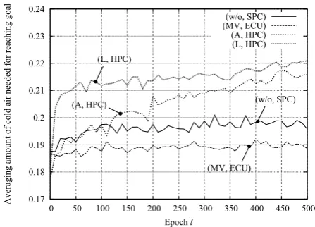
In Fig.11, a smaller amount of cold air means more energy efficient. We obtain a little bit unexpected results. Among them, the method (MV, ECU) is the best despite that it does not take into account excess cooling. This is because (MV, ECU) prefers lower cooling strength. Therefore, the needed time was largest. It is observed that both of (A, HPC) and (L, HPC) increase with the number of epochl. This is because their needed time decreases with the number of epoch l. We can observe that there are tradeoff between the needed time and the energy efficiency. However, the difference on the amount of cool air is not so large, that is, at most approximately 2%.
VI. CONCLUSION
In this paper, we proposed the air conditioner (AC) control system based on users’ sensations. The purpose was to realize the control system that improves the low-performance AC in terms of energy efficiency and comfortableness perfor-mance. The system trained the control policy by using Q-learning with entered users’ sensations. In order to cope with the large number of users, we proposed three types of integration methods of users’ sensations. Especially, the proposed method based on likelihood was the most effective in terms of the time required for the control. Further, in order to reduce the energy consumption in cooling, we proposed several reward functions, which penalize the policy performing excess cooling. However, we could not confirm that the penalties clearly reduce the energy consumption. Instead, we confirmed that there exists a tradeoff between the speed of control and the energy consumption. One of our future works is to overcome the tradeoff.
REFERENCES
[1] K. Sato, M. Samejima, M. Akiyoshi and N. Komada, “A Scheduling Method of Air Conditioner Operation using Workers Daily Action Plan towards Energy Saving and Comfort at Office,”2012 IEEE 17th Conference on Emerging Technologies and Factory Automation, pp. 1-6, 2012.
[2] M. Bal, “Industrial applications of collaborative Wireless Sensor Net-works: A survey,”2014 IEEE 23rd International Symposium on Indus-trial Electronics, pp. 1463-1468, 2014.
10 20 30 40 50 60
0 50 100 150 200 250 300 350 400 450 500
T
im
e
ne
ede
d
for
re
ac
hi
ng
g
oa
l
Epochl
(w/o, SPC) (MV, ECU) (A, HPC) (L, HPC)
(w/o, SPC)
(L, HPC) (MV, ECU)
[image:6.595.158.436.64.198.2](A, HPC)
Fig. 10. Time needed for reaching goal at each epochl.
0.17 0.18 0.19 0.2 0.21 0.22 0.23 0.24
0 50 100 150 200 250 300 350 400 450 500
A
ve
ra
gi
ng
am
oun
t
o
f
col
d
ai
r
ne
ede
d
for
re
ac
hi
ng
goa
l
Epochl
(w/o, SPC) (MV, ECU) (A, HPC) (L, HPC)
(w/o, SPC)
(MV, ECU) (L, HPC)
(A, HPC)
Fig. 11. Averaging amount of cold air needed for reaching goal at each epochl.
[3] C. Tunca, H. Alemdar, H. Ertan, O.D. Incel and C. Ersoy, “Multimodal Wireless Sensor Network-Based Ambient Assisted Living in Real Homes with Multiple Residents,”Sensors, Vol. 14, No. 6, pp. 9692-9719, 2014.
[4] J. Si, A. Barto, W. Powell and D. Wunsch, “Robust Reinforcement Learning for Heating, Ventilation, and Air Conditioning Control of Buildings,”Handbook of Learning and Approximate Dynamic Program-ming, pp.517-534, Wiley-IEEE Press, 2004.
[5] T. Hiroyasu, A. Nakamura, M. Yoshimi, M. Miki and H. Yokouchi, “Lighting Control System using an Actor-Critic type Learning Al-gorithm,” 2010 Second World Congress on Nature and Biologically Inspired Computing, pp. 140-145, 2010.
[6] C.J.C.H. Watkins, “Learning from Delayed Rewards,” Ph D Thesis, University of Cambridge, England, 1989.
[image:6.595.313.537.417.578.2]