High-speed single-electron memory: cell design and architecture
Hiroshi Mizuta, David Williams
,Kozo Katayama, Heinz-Olaf Mtilier, and Kazuo Nakamo
Hitachi Cambridge Laboratory. Hitachi Europe Ltd.. Madinglq Road, Cambridge CB3 OHE, UK
Haroon Ahmed
Microelectronics Research Centre. University of Cambridge, Madingley Road, Cambridge CB3 OHE. UK
Abstract
A new silicon-based single-electron memory cell is presented for use as a high-speed RAM. Novel architectme and operation schemes are evaluated by conducting Monte Carlo single-electron simulations. By performing transient waveform analysis. a lugh-speed write operation IS demonstrated with a
wnte time shorter than IO nsec.
L-SEM (Lateral Single Electron xemory) cell
The L-SEM architecture is mtended to achieve high-speed write operanons comparable to DRAM operation. In this new memory-cell (see Fig.l(a)), an m-plane MTJ Multiple Iunnel ,!unctionl [I] is mtegmted into the gate of a MOSFET (Metal-QxideSermconductorm), and the write operation IS achieved
by the electrons tunnelling through the MTJ between the word electrode and the memory node.
The lateral size of the T-shaped memory node region may be chosen of the order of a few tens of nanometers to meet the current lithography conditions. Therefore. the single-electron memory operation is generahsed in the L-SEM cell by employmg CB (coulomb Blockade) due to multiple electrons ranging from a few to a few tens rather than purely one. The stored memory node voltage is sensed by monitonng the current through the MOS channel induced under the memory node. The memory-cell array consists of one L-SEM device connected to the source. data and word lines (Fig. I(b)).
iai W
F/g i /a/ L-SEMsrrucrure and !b! memon -cell arc)’
This is a different operation principle from those of other quantum-dot single electron memory cells [2]-[4] where charge injection is done between the MOS channel and the nanometre-scale memory node through the gate oxide. These quantutnQt memory cells are classified as non-volatile memory, and have in general long data retention times. However. the wnte’etase operations of these memory cells are inherently slow, typically ranging from 10” to IO” seconds. since the operations rely on the Fowler-Noniheim runnelling currents through a solid oxide barrier under large elecmc fields.
The L-SEM cell structure with the MTJ has several advantages. Firstly. it enables larger tunnelling currents. resulting in faster charging 1 discharging operations. Secondly. because of its gain cell nature, the L-SEM overcomes the inherent low-noise-margin issue of the conventional one-nansistorione-capacitor (1-T) DRAM ceils. Thirdly, the use of the MTJ suppresses the leakage current due to co-tunnelling. Finally, the cumbemome off* charge effects may be reduced: this issue will be discussed in the last section of this paper.
ii
!t
common so vonage (v) Common SO vottaga 0
fig. 3 T h e h y s t e r e s i s l o o p sf Ihe memon, n o d e volrage as a fiu~crron of common source and dara volrage.
When such a voltage sequence is applied. the L-SEM shows node voltage hysterests as shown in Fig. 3. The simulatton was done at 4.2K for an L-SEM with a j-nm-dot MTJ and for zero tnmming gate bias. For writmg ‘0’ (right-hand side). a positive bias of 0.1 V is first applied to both the source and data electrodes. A negative voltage pulse of -0. I2 V is then applied to the word to inject electrons mto the memory node? AAer a positive word voltage pulse of 0.12 V is apphed. the source arl data voltages are finally turned off to zero. and the operation point moves to the final state ‘0’. For writing ‘ 1’ (let?-hand side), a negative bias of -0.1 V IS first applied to both the
source and data electrodes, and other sequences are the same as those for writing ‘0’.
The upper and lower branches of the hysteresis correspond to +3Se (the absence of 35 electrons) and -35e (the presence of 35 electrons) charge states. respectively. The stze of the hysterests may be varied by tuning the tnmming gate btas. The full sequences for writing ‘0’ and ’ 1’ selectively to the cell M,, are summarised in army circtmdtagmms tn Fqs. 4 and 5. The
memory-cell consists of one L-SEM devtce connected to the source&data lmes and word lure. In Ftg. 4 the left column
shows the sequences to write ‘0’ selecttvely to the memory-cell M, ,. Fust a positive btas of 0.1 V IS applted to both the source and data lines connected to M , , The right column deptcts the operation point of the memory indtcated in (VmdC. V,,) space. ln this representation the negative voltage pulse of -0. I2 V apphed to the word line shifts the blockade region downwards. Under these circumstances. smce the operatton pomt IS outside the
blockade regton. it can not stay here and so moves to Inside.
Third. the positive word voltage pulse of 0.12 V is applied and this operation point remains to stay m the same place. Fina,lIy. the source and data voltages are turned off to zero. and the opetatton point moves to the final state ‘0’.
\ *my corm ohgram
0. v O.lV 0 v
9”
ovvtected
cell ’
/ /q
1 L H? IMiZ
ov
El
km u+1
0.4 v
oiv
ov
QV4
2
vsv
-017v 1 I OIV
F/g 4 Sequetlces,tbr w~nrrnp ‘0’ selecrr\,eh ro r h e memn/~ crll .Ai,. .4/l rhe \,olrage paramerers are chosen /Or rhe L-SE.\1 w irh 5 I 5 nnr’-rsland-.lfTJ Ii!, and 1 H are 0 II’ and 0 12 I’
High-speed write operation of L-SE\1
\ Army clroun obgmm qv -0.y pv qv
4
0
-0lV " memos
.; VrmOs _____ ___
0
Iri '1'
1
VW
_a__ __v__ -017v
-0lV’
L-SEM with 2D network tunnel junctionFig. 5 S e q u e n c e s / o r wnrrng ‘I’ se1ecrwel.v 10 [he memory cell M,,
Fast switching is achieved between high and low levels WI&I a switching time as short as 10 nsec. Details of discrensed chargmg’discharging steps can be seen in Fig. 6. We investigated the effects of the word voltage pulse height on these write operations. Figure 7 (a) shows the transient of the memory-node voltage for various values of Vw. It can be seen that the switching becomes faster with increasing VW since a
larger VW results in a larger tunnelling current through the
MTJ. leading to faster charging-up. In Fig. 7(b). the switching time tTHL is plotted as a function of VW. The switching occws above a certain threshold voltage and then tTHL decreases rapnily. This IS because a larger tunnelling current flows with increasmg
VW over the critical voltage. and t,,.,, approaches the limit determined by Cr R. it can be seen that trHL can be redu& to less than 10 nsec for the present S-nm-islands L-SEM cell structure
F....i....i
i ....
1.’1
0 loo 200 300 4ca 500
Time (IIS)
I
0 100 2cul 300 600 500
[image:3.612.290.540.72.430.2]Time (nr)
FIG p C_wle tlmlng dragrams and tb)) and correspondrng rransretinr memory node voltage and eleccrron number srored on the memory node (tc))jor wnfe sequences
An alternative L-SEM cell structure with a 2D network tunnel junction (NTJ) (see Fig.8(a)) was also examined to achieve a further improvement of the write operation. Larger tunnel currents are expected for the NTJ structure simply because the channel width is effectively increased. Such XTJ structures may be realised in metal-dot tunnel junction devices. An equivalent circuit is shown in Fig. 8(b) for a 6 x 7 tunnel junction army. The I-V characteristics and t,,-Vw dependence simulated for the L- SEM with 2x2-r&-island NTJ are show in Figs. 9(a) and (b), and compared with the results for 2x2-tin?-island MTJ shown in Fig. 9(b).
[image:3.612.50.275.74.481.2]015
E
0106
5 005
%
O
[I:
I-0 15
W ord
trimming
Network
hm-tel
jlJllCti00
Drain
TL-‘SEM wilh’5-nm-is&d MTJ
L.----L
T = 4.2K150 _c----,-_(b)
140 160
Vword (mV)
Ftg 7 (a) Transrenr m e m o r y n o d e volrage srmulared H.llh various values of VW /or rhe L-SEM wlrh 5x5-nm-‘-tsland MTJ ai 4.2K lb)
Vwdependence of I~,,~
Discussion on Offset charge effects
In this final section, we discuss the offset charge effects in the L-SEM cell. We have so far constdered an ideal memory system without any fi-acttonal background charge. However. charged defect states at silicotioxtde interfaces are more or less inevitable in the real device structures, which may cause senous effects on the memory operations. From the stand-point of memory design, the most crucial effect of the offset charge IS
uncontrollable change in the critical voltage. If the offset charge on each island varies in a random manner, the critical voltages of the MTJs in the memory army are also scattered completely,
and there will ‘be a fume probabthty that the CB of the MTJ 1s broken and the stored data cannot be retamed m some memory cells. In these circumstances. a new ctrcutt operanon which IS
independent of background charge IS necessary [6].
Source Memory node
@I
Drain
Flp 8 la) L - S E M wrrh . ? D nemork funnel Juncrron fbl 4 quanlutn equlvalenr CWCUI~ for [he L-SE.U lc.lrh .vTJ
8.0
z70 (al
I
ap 60 0 5.0 z40
E 3.0 T = 4.2K e! 2-nm-idands 5 2.0
0 1 0
0 .-. ‘
-0 0 5 1 1 5 2
or I---I 1 1 1--.1---1--J
520 540 560 560 600 620 640 660 660
FIN 9 la) I-L’characlensltcs and 16, I;,,.-I’m cun’e srmuiared lbr rhe L-SE.\! The .I’TJ IS compared H rrh Ihe .MTJ a! 4 2K
However. a densq of interface defects achteved m recent siltcon process technologtes is typically of the order of IO“‘cm”. whtch results tn. at most. only a few defects over the core MTJ area of the single L-SEM-cell. As long as the offset charge IS
introduced. The defect is assumed to be located in 2 nxn distance from the chain of the islands. and is moved parallel to the chain (see Fig. 10).
f
30 nm
P
2nm
n
BD~HDD
i
2nm
[image:5.620.290.518.75.217.2]____________ +
single-charged defect
Fig. IO MTJ wuh a smgle charged defect conjigurarton
8
s 0.2 =
g 0.15 3
g 0.1 0)
5 d 0.05
n
1-15 -10 -5 0 5 10 15
Meal posltion x (nm)
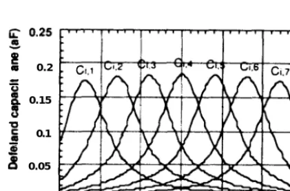
Fig. I I The charge on each island tnduced by a stngle deject charge plorred as ajimmon of rhe defect posirlon The mduced charge is
plotted as an efleccrwe capacuance between the defect and islandr.
.Figure 11 shows the defect position dependarce of the charges induced OD each island. The capacitance parameters between the defect and islands were obtained from these results. In the single-electron circuit simulations, the single defect IS m0deIled as an extra n0de with a smgle negative charge, -e, on it. The position-dependent capacitance parameters were then inmxiuced to the equivalent circuit as addihonal capacitances. Simulations for the I-V characteristics were repeated by moving a single defect charge from the one edge to the another of the MU. The critical voltages taken from the I-V chatacteristlcs were plotted in Fig. 12 as a function of defect position.
Statistical analysis was perf0rmed on these results: the distribution of the upper critical voltages was plotted in Fig. 13. The entire distribution looks like a Poisson distribution with a main peak which is slightly below the original critical voltage of 0.2 V. It should be ooted that distribution has a tail towards the larger voltage regime. but no fmite probability IS
seen around zero critical voltage. This means that blockade’state is always maincliaed m&p&ent of defect positions. This is because many of the tunnel junctions m the MTJ can act to provide a good blockade even though s0me of the tunnel junctions close to the defect are broken.
Orlginal CB region
I
-1.5
0 5 10 15 20 25 30
Ftg. I.? @per and lower cnbcal volrages calculated bv movrng a mgle charged dqfecr m parallel IO rhe MTJ.
50 +Original critical voHage
40
10
0
0 0.1 0.2 0.3 0.4 0.5 0.6 0.7
l
Ftg. 13 Dlsrnbur~on c$ the upper crirical volrages rnduced by a srngle defecr charge.
In addition. a well defined main peak in the distribution still enables us to work m the same manner as that for an ideal system. This IS indeed a big advantage of the MTJ compared
with a single tunnel junction in which the blockade is detemuned only by one tunnel junction. Therefore. as long as the number of the charged defects in one cell is kept smaller than the number of the tunnel junction in the MTJ. the L-SEM structure is robust for offset charge problems. These considerations are deplcted in Fig. 14. In this figure a solid line represents &f&t densities which provide one defect per one island area of the MTJ. Ttus indicates that the MTJ with istand size as small as a few manometre satisfies thus criterion. and the L-SEM with such MTJs can operate without having special circuit arrangements.
t
[image:5.620.44.255.253.392.2]h Offset-charge-free
Ijk circuits
1 Silicon/oxide
interface defect density
In
10n
100n
lp
Island diameter (m)
Fig. 14 The shaded region represents rhe condltron in which the L-SEM with rhe MTJ work despite the charged dejects. .4bove rhe boundary a diferenr offsergharge-free circurr scheme 1s required.
Conclusion -c
New L-SEM cell design and architecture based on the MTJ were presented for use as a high-speed RAM. A unique few electron operation scheme was shown by conducting single-elecuon circuit simulations, and a higb-speed write opetanon was demonsXr&d with a charging/diiharging time shorter than 10 nsec. The robusmess of the L-SEM was also discussed in terms of the offset charge issue.
Acknowledgement
The authors would like to thank Dr M. Wagner for his support for 2D capacitance calculations, and also Dr. 2. Durrani. Dr A. Irvine, and Dr K. Tsukagoshi for their valuable discussions. This Work was performed within the ESPRIT MEL-ARI PrOJeCt FASEM (Fabrication and Architecture of Sin&Electron Memories).
References
[l] K. N-to, R. Blaikie and H. Ahmed. “Singleelectron memory”, J. Appl. Phys. 75, 5123, 1994.
[2] J. J. Welser, S. Tiwari, S. Rishton, K. K. Lee, aml Y. Lee, “Room tempetature operation of a quantum+k% flash memory, ED43, 1553, 1996, also in Appl. Phys. L..ett. 68,
1377 1996.
[3] L. Gue, E. Leobandung and S. Chou, “A roomhemperature silicon single-electron metal-oxide-semiconductor memory with nanoscale floating-gate and ulaanafro w channel”. Appl. Phys. Len. 70, 850. 1997.
[4] K. Yano, T. Ishii, T. Hashimoto, T. Kobayashi. F. Murai, and K. Seki. “Room-temperature single-electron memory”, IEEE Trans. on Electron Devices, ED41. 1628, 1994. [5] K. Nakazato and J. White, “Single-electron switch for
phase-locked single-electron logic devtces”. Prm of IEDM 92. 487, 1992.
[6] N. Korotkov and K. K. Likharev, -Analysis of Q,-mdependent Single-Electron Systems Inr. W&hop on Computational Electronics (IWCE). Tempe. Arizona,