ISSN Online: 2327-6053 ISSN Print: 2327-6045
DOI: 10.4236/msce.2018.63006 Mar. 26, 2018 68 Journal of Materials Science and Chemical Engineering
Synthesis of Zeolite LTN-(SOD) Self-Supporting
Membranes from SiO
2
-Rich Industrial Waste
Valeriy Petrov, Josef-Christian Buhl
*Institute of Mineralogy, Leibniz University Hannover, Hannover, Germany
Abstract
Synthesis of zeolite LTN (“Linde Type N”) was investigated under insertion of a SiO2-rich filtration residue (FR) from waste water cleaning of the silane production. A new synthesis procedure was therefore developed applying a flotation mechanism with the aim to grow LTN in form of thin membrane like sheets. Preparation starts with preactivation of FR by slurrying first in al-kaline solution, followed by an addition of aluminate solution and citric acid. The latter was added as suitable chelating agent for the initiation of the flota-tion process. In the course of these experiments, we succeeded in synthesizing zeolite LTN with more or less zeolite SOD as byproduct in the form of a stable compact membrane-like layer at low temperature of 60˚C. The crystallization was performed under isotherm static conditions in an open reaction system without addition of organic templates as structure directing agents (OSDA’s). FR was utilized as a total substitute of sodium silicate in all experiments and an expansive pre-treatment procedure like calcinations was not needed. Fur-thermore, membrane formation with LTN of usual synthesis needs chemically functionalized supports. In contrast self-supporting membranous LTN layers were grown for the first time in the present study.
Keywords
LTN Zeolite, Self-Supporting Membrane, 60˚C Synthesis, Industrial Waste, Flotation
1. Introduction
Zeolites are microporous materials, widespread in industry as molecular sieves, ion exchangers and catalysts, mostly applied as polycrystalline powders or in pellet form [1]. Beside insertion of zeolites as dense packages even their use in form of membranes becomes more and more important within the last years. How to cite this paper: Petrov, V. and
Buhl, J.-Ch. (2018) Synthesis of Zeolite LTN-(SOD) Self-Supporting Membranes from SiO2-Rich Industrial Waste. Journal
of Materials Science and Chemical Engi-neering, 6, 68-84.
https://doi.org/10.4236/msce.2018.63006
Received: February 23, 2018 Accepted: March 23, 2018 Published: March 26, 2018
Copyright © 2018 by authors and Scientific Research Publishing Inc. This work is licensed under the Creative Commons Attribution International License (CC BY 4.0).
http://creativecommons.org/licenses/by/4.0/
DOI: 10.4236/msce.2018.63006 69 Journal of Materials Science and Chemical Engineering Zeolite membranes are significant for chemical processes like separation of gases and azeotrope phase mixtures. Also in other areas of material design like sensor technology, a rising interest in zeolite membranes is registered. Caro and Noack [2] give an excellent overview above the early state up to 2008. The group of Kapteijn describes the following development in view of new technologies up to 2016 (Kosinov et al. [3]).
At present, zeolite membranes were mostly synthesized on supports (e.g., Al2O3) and first a functionalizing step of the support material by chemical treat-ment is necessary for a formation of sufficient dense zeolite sheets in the subse-quent hydrothermal crystallization process. The hydrothermal synthesis in au-toclaves is the nearly exclusively used procedure for the crystallization of the membranes on the support materials. Larger synthesis periods or several synthe-sis steps are necessary to produce layers of required quality [4] [5] [6] [7] [8].
While primarily membranes of the structural types LTA and FAU came to application, membranes of other zeolite structures are of increasingly interest and modified methods of synthesis were developed. Newly membranes of small pore zeolites like zeolite SOD were tested as water sorbents in chemical processes for cleaning of methanol or dimethylether and dimethylcarbonate [9]. Insertion for water desalination [10] [11], esterification-coupling reactions [12] and the H2/CO2 separation during water gas production from coal [13] are further future applications of small-pore zeolites.
Considering those new applications of zeolite SOD, other framework types with small pores will be centered in future. In the present work we study the synthesis of membranous thin sheets of polycrystalline LTN zeolite. The LTN type zeolites own a complex framework whose topology can be described by dif-ferent models as discussed in summary in [14]. Beside the description in form of the two substructures of SOD and KFI [15] [16], the topology even results from a linkage of CAN cages and double six rings D6R [17]. All these different models lead to a structure with distorted α-cages (grc-units [18]) known from the LTA framework in undistorted form [1]. The LTN framework exhibits no canal sys-tem and its largest opening forms a 6-ring, as in the SOD structure type, because the larger eight-rings of the distorted grc-units of LTN are blocked by the six-rings of the adjoining cages [19]. Zeolite LTN (also termed Linde Type N [15] or NaZ-21 [20]) has one of the largest unit cells of all zeolites known up to now (cubic, a0 = 35.6 Å, SG: Fd3-m [21]). The ideal chemical composition is Na384 (H2O)518 [Al384 Si384 O1536] [21].
The first technical application of zeolite LTN is an insertion as catalyst, as the creation of acid sites inside the LTN framework results in a zeolite with ideal re-lation between weak acid sites and medium to strong acid sites and the expan-sive rare earth doped ultrastable Y-zeolite, widely inserted in catalysis, can be substituted by this modified much cheaper LTN-material [22].
poly-DOI: 10.4236/msce.2018.63006 70 Journal of Materials Science and Chemical Engineering crystalline material with a particle size up to 3 µm could be observed under syn-thesis by microwave heating. This synsyn-thesis was successful even under insertion of colloidal silica (LUDOX from Aldrich [24]) instead of sodium silicate solu-tion. Even SiO2-rich powders of industrial wastes like, ashes, filtration residues, slag and many others, are suitable educts for zeolite synthesis, if their chemical composition is without elements or components being harmful to the environ-ment, as demonstrated in many experimental works [25]-[37].
During our previous study on zeolite synthesis the insertion of a nanosized powdered silica-rich filtration residue FR obtained from waste water recondi-tioning of the silane production was even found to be very suitable for zeolite crystallization under open system conditions at low temperature [38] [39] [40].
In the present study, we describe a modified reaction pathway for zeolite LTN synthesis under insertion of this silica-rich filtration residue FR. Our main aim was not only synthesis of LTN zeolite in polycrystalline powder form but also the preparation of membrane-like zeolite sheets. Therefore we describe here a method of particle separation by flotation, generated by the addition of citric acid as a chelating agent. An enrichment of the reactants at the surface of the reaction volume is thus reached with a decisive influence on the crystallization.
2. Experimental
2.1. Starting Materials
The Si-rich filtration residue (FR) was kindly provided together with chemical analysis data from the Federal Institute for Materials and Testing, BAM-Berlin. These data, obtained by optical emissions spectrometry with inductively coupled plasma (ICP-OES) under use of an iCAP 6000 device (Thermo Scientific) are summarized in Table 1. Our X-ray powder investigation of FR revealed its mainly amorphous character, beside a very low amount of calcite. The material consists of nano-particles. Only some agglomerated grains reach dimensions not larger than 1 µm. Beside FR as Si-source sodium aluminate, Riedel-de Haën 13,404, sodium hydroxyde, Merck 1.06467 and citric acid, Fluka 27,490, were used as further educts of our syntheses.
2.2. Experimental Conditions
From the literature overview [41] [42], one can find out that the synthesis para-meters temperature ~100˚C and time ~1 h are often used for LTN. Besides tem-perature and time the concentration fitting for the LTN formation Si/Al-ratio in the educts amounted 1 and the NaOH concentration varied in the prevailing
Table 1. Chemical composition of FR.
Chemical composition (Wt. %)*
SiO2 Al2O3 Fe2O3 TiO2 CaO MgO Na2O K2O SO3 Cl− Loss of ignition
92.30 3.83 0.49 0.05 2.05 0.19 0.01 0.05 0.23 0.80 3.23
DOI: 10.4236/msce.2018.63006 71 Journal of Materials Science and Chemical Engineering case at about 8 M/l. On the basis of these parameters we modified the synthesis system by inserting an additive for initiation of a flotation process with the aim to reach a particle transport in direction of the surface of the reaction beaker for crystallization of membrane-like zeolite sheets. We selected citric acid as chelat-ing agent. The deprotonation reaction of this carbonic acid yields to formation of carboxyl groups according to reaction (1):
2
COOH OH COO H O
R− + −→ −R −+ (1)
These groups are complexing agents for Al- and Si ions [43] and micelles (also termed globules [44] [45]) will be formed. Air bubbles attach these complexes and cause a particle uplift, i.e. a flotation effect [46]. The resulting concentration gradient between the bottom and the top of the reaction vessel rules the forma-tion of a zeolite sheet.
The flotation process is ruled by the specific boundary surface energies be-tween solid (micelle) liquid phase on the micelle surface and the gas bubbles (air bubbles). The adhesion strength of the bubbles on a wetted solid surface is de-scribed by Equation (2) [46]:
A O σ
∆ = ∆ ⋅ ∆ (2)
where:
A: adhesion strength; ΔO: contact surface;
Δσ: difference of the specific boundary surface energies before and after adhe-sion of the bubbles and can be calculated according to Equation (3) [46]:
solid/gas+ gas/liquid solid/liquid
σ σ σ σ
∆ = − (3)
with
σsolid/gas: specific boundary surface energy between solid and gas;
σgas/liquid: specific boundary surface energy between gas and liquid;
σsolid/liquid: specific boundary surface energy between solid and liquid.
The adhesion strength A is as stronger as larger Δσ will be. Young’s contact angle equation (Equation (4), [46]) provides a further gauge for the degree of adhesion
(
)
gas/fluid 1 cos O
σ σ δ
∆ = − ∆ (4)
where: δ: contact angle.
The adhesion strength A is as larger, as larger both the contact angle δ and
σgas/fluid are [46].
Under consideration of the insertion of citric acid as complexing additive for initiating and ruling this flotation process, we developed a modified synthesis concept consisting of preparation and combination of three solutions: solution 1) serves for preactivation of the FR in alkaline medium. Solution 2) is the acid additive solution and solution 3) the aluminate component.
DOI: 10.4236/msce.2018.63006 72 Journal of Materials Science and Chemical Engineering in Table 2.
The synthesis batches consist of a mixture of the three separate produced so-lutions as follows:
Synthesis 1:
Solution (1)—2g FR+30 ml H2O + 17.0 g NaOH were mixed by stirring for 15 min. at 85˚C;
Solution (2)—25 ml H2O + 4.2 g citric acid, mixed by stirring for 15 min. at 85˚C;
Solution (3)—50 ml H2O + 12.6 g NaOH + 2.3 g NaAlO2, mixed by stirring for 15 min. at 85˚C.
The solutions were mixed in the order 1 - 3 (ascending order) in a beaker glass.
Crystallization was performed by heating in a cabinet dryer for 3 days and at 85˚C without stirring.
Synthesis 2:
Solution (1)—2 g FR + 30 ml H2O + 17.0 g NaOH were mixed by stirring for 15 min. at 60˚C;
Solution (2)—20 ml H2O + 4.2 g citric acid, mixed by stirring for 15 min. at 60˚C;
Solution (3)—50 ml H2O + 12.6 g NaOH + 2.3 g NaAlO2, mixed by stirring for 15 min. at 60˚C.
The solutions were mixed in the order 1 - 3 (ascending order) in a beaker glass.
Crystallization was performed by heating in a cabinet dryer for 7 days and at 60˚C without stirring.
Synthesis 3:
Solution (1)—2 g FR + 30 ml H2O + 16.5 g NaOH were mixed by stirring for 15 min. at 60˚C;
Solution (2)—25 ml H2O + 4.2 g citric acid, mixed by stirring for 15 min. at 60˚C;
Solution (3)—50 ml H2O + 12.0 g NaOH + 2.3 g NaAlO2, mixed by stirring for 15 min. at 60˚C.
The solutions were mixed in the order 1 - 3 (ascending order) in a beaker glass.
Crystallization was performed by heating in a cabinet dryer without stirring for temperatures and times, given in Table 2.
Table 2. Experimental conditions.
No. of synthesis
Activation Alkalinity/Acidity Solution No. Synthesis
T, ˚C t, min (H 1
2O:NaOH)
2 (H2O:C6H8O7)
3
(H2O:NaOH) T, ˚C t, days
1 85 15 1.8 5.9 4.0 85 3
2 60 15 1.8 4.8 4.0 60 7
DOI: 10.4236/msce.2018.63006 73 Journal of Materials Science and Chemical Engineering
2.3. Characterization
All products were analyzed by X-ray powder diffraction (XRD), scanning elec-tron microscopy (SEM) and energy dispersive X-ray spectroscopy (EDXS).
X-ray powder diffraction was performed using a Bruker D4 Endeavor diffrac-tometer (Bragg-Brentano geometry, monochromatic CuKα radiation, 2 Theta range 3˚ - 85˚, step width 0.03˚ 2 Theta, measuring time of 1 sec per step). The WinXPow software (STOE) and the powder diffraction file [47] were used for data evaluation. For a better overview on the powder patterns each pattern was shown as expanded plot in the 2 Theta range of 5˚ - 50˚ as usually done in the IZA collection of simulated powder patterns for zeolites [48].
SEM investigations were performed on a JEOL JSM-6390A SEM at an accele-ration voltage of 30 kV respectively to characterize the morphology and homo-geneity of the samples. The composition of the products was estimated by EDXS. The SEM was therefore equipped with a Bruker Quantax-200 EDX system and an X flash detector 410-M.
3. Results and Discussion
[image:6.595.60.537.395.680.2]The XRD patterns of the products are summarized in Figure 1. Analysis results were obtained on the basis of the collection of simulated zeolite powder Data [48], the powder diffraction file PDF [47] and the zeolite structure information atlas [21].
Figure 1. X-ray powder patterns of samples 1a - 3a and 1b - 3b. The main lines of the byproduct zeolite SOD in the samples are
DOI: 10.4236/msce.2018.63006 74 Journal of Materials Science and Chemical Engineering The reaction products of all three syntheses are summarized in Table 3. The products accrued in two main sequences as illustrated in Figure 2 in the lower and upper part of the reaction beaker. Thus it was decided to describe these synthesis products (“a” and “b”, Table 3) in separate sections.
The following sequences were observed:
- In the lower area of the reaction beaker: here fine disperse or compact poly-crystalline zeolite SOD was found beside more or less LTN (samples 1a, 2a and 3a; Table 3);
- In the upper area: LTN and small amounts of SOD in membranous form was deposited (samples 1b, 2b and 3b; Table 3). The further investigations of these samples revealed that the sheets consist of 2 or 3 thin sublayers (see upper layer (b) in Figure 2 with its top-, middle- and bottom sequence).
3.1. Samples 1a and 1b
[image:7.595.211.540.361.490.2]The synthesis product of experiment 1 consists of grey material in the lower part of the reaction beaker (1a) and a stable white sheet in the upper part (1b). The X-ray powder patterns of both products show LTN as a main phase (PDF
Table 3. Reaction products.
Name of
sample* Color of sheet Phases** Number and composition of subsequences***
1a Grey LTN + SOD ~
1b White LTN + (SOD) 3: top – LTN, 1 μ; middle – LTN, 3 - 5 μ; bottom – LTN, 7 - 10 μ
2a Grey LTN + SOD ~
2b White LTN + (SOD) 2: top – LTN, 6 μ; bottom – LTN, 10-20 μ + SOD, 10 μ
3a Grey SOD ~
[image:7.595.243.502.525.681.2]3b White LTN + (SOD) 2: top – LTN, 1 - 2 μ; bottom – LTN, 10 - 20 μ + SOD, 7 μ *a: product in lower area, b: product in upper area; **( ): low amounts; ***according to SEM investigation, see text.
Figure 2. Right: Scheme of the distribution of the products (a) and (b)
DOI: 10.4236/msce.2018.63006 75 Journal of Materials Science and Chemical Engineering 27-1405) beside portions of SOD. The difference between the samples 1a and 1b persists in the amount and type of SOD. The sample 1a of the lower area of the reaction beaker, shows a larger part of SOD and the whole amount of SOD is hydrosodalite (PDF 42-216; Figure 1), whereas product 1b contains more mod-erate parts of SOD, but in form of basic sodalite (PDF 42-215).The white sheet-like product 1b, formed in the upper part of the beaker glass was 3 mm thick and showed a high mechanical stability and firmness, so that it was possi-ble to take the whole layer out of the beaker. Only a detailed SEM analysis of the sheet revealed, that it was built up of three sublayers with LTN crystals of dif-ferent size (see SEM analysis below and the data in Table 3).
The SEM investigation of sample 1a (Figure 3, SEM-image at the top) shows cubic LTN crystals and SOD phase. The LTN crystals exhibit a size of 0.5 to 5 μ and show strong intergrowth and aggregates. SOD crystallized in tabular isometric crys-tallites and even forms agglomerates. The size of the cryscrys-tallites is 0.5 μ and smaller.
The EDX measurements (area measurement of Figure 3(a)) yield to the fol-lowing chemical composition (Wt%): SiO2: 42.7; Al2O3: 33.1; Na2O: 21.0; CaO: 2.9; Cl: 0.3. The Si/Al-ratio is 1.1. Point analysis on LTN crystals and SOD crys-tals (not shown) indicate that the Ca and Cl parts from the FR are mainly con-centrated in the SOD-zeolite and hardly in the LTN phase.
The SEM investigation of sample 1b shows well developed, sharp edged cubic crystals of LTN which form a polycrystalline layer by strong intergrowth (Figure 3, SEM-image in the middle). The EDX-area analysis of these crystals proved the following chemical composition (Wt%): SiO2: 43.4; Al2O3: 34.7; Na2O: 21.9. The Si/Al-ratio was ~1.1.
A further detailed investigation of sample 1b presents the complicated con-formation of the upper layer (Figure 3, SEM-image below). It was found out that this white layer is built up by a stacking of three sublayers. The borders of the sequences are well recognizable as step-shaped breaks. The upper sequence lies on the right and on top in the SEM-image (Figure 3, image below) and con-sists of LTN of about 1 μ and appears with columnar texture. The intermediate layer appears again with columnar LTN crystals of 3.5 μ. The big LTN crystals (approx. 7 - 10 μ) left down in the image belong to the third layer. The chemical composition of these large crystals amounts (Wt%): SiO2: 43.6; Al2O3: 34.3; Na2O: 22.1. The Si/Al-ratio is 1.1.
3.2. Samples 2a and 2b
DOI: 10.4236/msce.2018.63006 76 Journal of Materials Science and Chemical Engineering
Figure 3. SEM image (left) and EDX-spectrum (right) of samples 1a and 1b.
DOI: 10.4236/msce.2018.63006 77 Journal of Materials Science and Chemical Engineering the main phase, the white sheet-like sample 2b consists of LTN as main phase and a lower part of SOD, but in form of basic sodalite (see Figure 1).
SEM images of products 2a and 2b are summarized in Figure 4. Sample 2a (image on top of Figure 4) exhibits the cocrystallization of SOD and LTN in the product of the lower part of the reaction glass. The LTN admixture is grown to-gether with aggregates of SOD-crystallites. The LTN cubes are 2 μ and tabu-lar-shaped and SOD crystals are 1 - 2 μ big.
The chemical composition (area analysis of the SEM detail of Figure 4 on top) amounts (Wt%): SiO2: 42.2; Al2O3: 34.1; Na2O: 22.4; CaO: 1.1; Cl: 0.2. The Si/Al-ratio is 1.0. The Ca and Cl parts from FR again enriched in SOD, as al-ready observed in sample 1a.
The SEM images of the sheet-like sample 2b, formed in the upper part of the reaction beaker are shown in Figure 4 (image in the middle and below). The cu-bic crystallites of LTN show intergrowths and aggregates. SOD-zeolite forms spherical intergrowths of numerous strip-shaped crystals. EDXS (area analysis of the detail of Figure 4, middle) presents the chemical composition (Wt%): SiO2: 41.6; Al2O3: 35.1; Na2O: 23.3. The Si/Al-ratio is 1.1.
The SEM image below in Figure 4 presents the assembly of double sequence of sample 2b. The upper subsequence consists of widespread and strong inter-growth of 6 μ large LTN crystals where as bigger LTN crystals (10 to 20 μ) and SOD in form of about 10 μ spherical intergrowths form the lower subsequence. The chemical analysis (Wt%) of the sample 2b is: SiO2: 40.8; Al2O3: 34.0; Na2O: 25.2. The Si/Al-ratio is again about 1.1.
3.3. Samples 3a and 3b
As experiment No. 2 failed to suppress SOD formation in experiment No. 3 the synthesis batch was further modified by slight reduction of the NaOH concen-tration as a further attempt to reduce the crystallization of the byproduct SOD.
As in synthesis No. 1 and No. 2 again a grey sample formed in the upper part (sample 3a) and a white sheet-like product was observed at the top of the reac-tion beaker (sample 3b). This sample was now thinner and more fragile, com-pared with the sheets of experiments 1 and 2. The latter was again composed of two sublayers, as demonstrated by SEM investigation (see above) but an exact spatial separation of the two sublayers and their preparation for SEM analysis was thereby more complicated.
The X-ray powder patterns of samples 3a and b are given in Figure 1. Here now only hydrosodalite SOD (PDF 42-216) was formed in the grey material of lower part of the reaction beaker (sample 3a). Again the growth of LTN (PDF 27-1405) and basic SOD (PDF 42-215) were analyzed in sample 3b, the latter only in small quantity.
DOI: 10.4236/msce.2018.63006 78 Journal of Materials Science and Chemical Engineering separation of the fragile thin sheet like sample 3b. Zeolite SOD forms aggregates of isometric crystals with a size less than 1 μ.
DOI: 10.4236/msce.2018.63006 79 Journal of Materials Science and Chemical Engineering
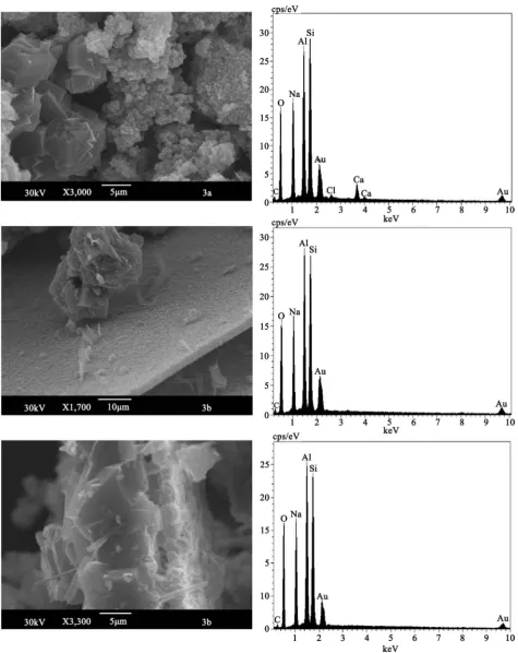
Figure 5. SEM image (left) and EDX-spectrum (right) of samples 3a and 3b.
DOI: 10.4236/msce.2018.63006 80 Journal of Materials Science and Chemical Engineering is 1.1. The Ca and Cl parts are again incorporated in SOD, as well as in the sam-ples 1a and 2a.
Figure 5 (SEM images in the middle and below) presents the complicated construction of the white layer sample 3b which exists at least of two subse-quences. The upper sequence with a LTN fragment is shown on the image in the middle of Figure 5. The small (1 - 2 μ) LTN crystals form here a tabular layer on which rare, strip-shaped SOD crystals grow. The lower image of Figure 5 shows the whole sheet of sample 3b in the cross section.
LTN and SOD can be distinguished in the lower part. The cubic crystallites of LTN show intergrowth, aggregates and twins. Their size amounts 10 - 20 μ. Zeo-lite SOD occurs as long strip-shaped crystals (Figure 5, both SEM images for sample 3b), with a length about 7 μ. The chemical analysis of the LTN (sample 3b) represents (Wt%): SiO2—43.0; Al2O3—34.5; Na2O—22.5. The Si/Al-ratio is 1.1.
3.4. Discussion
Our modifications of the classical zeolite synthesis method arose in crystalliza-tion series above and down in the reaccrystalliza-tion volume and membrane-like layers consisting of LTN as main phase and basic SOD as minor byproduct occurred and could be separated from the upper part of the reaction beaker. The changes of synthesis temperature (60˚C) and prolonged synthesis times (several days) alone are not sufficient enough to obtain the membrane like crystalline zeolite sheets. Thus our modified synthesis system is further based on the fact, that a nanosized silica source (FR) is used and preactivated in NaOH by slurrying. Be-side an aluminate solution a third component is required. This is the additive ci-tric acid, acting as chelating agent under generation of a flotation process, caus-ing an enrichment of the reactcaus-ing agents in the upper part of the reaction vo-lume with a decisive influence on the crystallization. The deprotonation reaction of the citric acid leads to carboxyl groups. They arrange themselves around cen-tral ions. Complex formation in particular with aluminum [43], however, also with silicon result in formation of micelles (globules [44] [45]) and the adhesion of air bubbles are causing a particle uplift known as flotation processes [46]. The resulting chemical gradient between the surface and the ground of the reaction beaker glass leads to the formation of stable layers of the crystallites under static isotherm conditions.
However, concerning results of this work and in comparison to investigations [49] [50], the kind of the ascending force mechanism of the components neces-sary for membrane formation must be further characterized for the improve-ment of the method, presented here. There are two hypotheses to explain this interaction of particles in liquid and gas bubbles [46]:
- “The immediate linking of gas bubbles on the particle surface of the FR or rather a developing electrically loaded double layer;”
surfac-DOI: 10.4236/msce.2018.63006 81 Journal of Materials Science and Chemical Engineering es with optimal conditions for a high chemisorption rate. Further investiga-tions are necessary to clarify this mechanism in more detail.
4. Conclusions
In this work, we demonstrated the cocrystallization of LTN and SOD zeolites in membranous form. It was observed, that products arose in crystallization series above and down in the reaction volume. Therefore modified synthesis condi-tions were found to be responsible, like using a nanosized silica source (FR), preactivated in NaOH, before the gel formation starts by addition of sodium aluminate.
The main finding of the experiments was the addition of citric acid as chelat-ing agent under generation of a flotation process. An enrichment of the agents in the upper part of the reaction volume with a decisive influence on the crystalli-zation was thereby obtained.
The layer like product, consisting of LTN as main phase and basic SOD as minor byproduct, could be mechanically separated from the upper part of the reaction beaker. Further modifications of the synthesis method are required to optimize this product. The influence of synthesis temperature, time and the ad-hesion process on temporal and spatial development of the zeolite crystallization in subsequences needs future attention. Maybe the procedure can be inserted for the production of the membranes of other zeolite types. A transferability of the results on syntheses with pure chemicals instead of FR as a Si-source should also be studied in future experiments.
Acknowledgements
The authors are grateful to the Dr. K. Ruebner, BAM-Federal Institute for Mate-rials and Testing Berlin, for kindly providing the FR raw material and for per-forming the chemical analysis of FR.
References
[1] Breck, D.W. (1976) Zeolitovie molekuljarnie sita. Mir, Moskva.
[2] Caro, J., and Noack, M. (2008) Zeolite Membranes—Recent Developments and
Progress. Microporous and Mesoporous Materials, 15, 185-197.
https://doi.org/10.1016/j.micromeso.2008.03.008
[3] Kosinov, N., Gascon, J., Kapteijn, F. and Hensen, E.M. (2016) Recent Developments in Zeolite Membranes for Gas Separation. Journal of Membrane Science, 499, 65-79.https://doi.org/10.1016/j.memsci.2015.10.049
[4] Wang, N., Liu, Y., Huang, A. and Caro, J. (2014) Supported SOD Membrane with
Steam Selectivity by a Two-Step Repeated Hydrothermal Synthesis. Microporous and Mesoporous Materials, 192, 8-13.
https://doi.org/10.1016/j.micromeso.2013.08.013
DOI: 10.4236/msce.2018.63006 82 Journal of Materials Science and Chemical Engineering
[6] Xu, X., Bao, J., Song, C., Yang, W., Lin, J. and Liu, L. (2004) Microwave Assisted
Hydrothermal Synthesis of Hydroxyl-Sodalite Zeolite Membranes. Microporous
and Mesoporous Materials, 75, 173-181.
https://doi.org/10.1016/j.micromeso.2004.07.019
[7] Kazemimoghadam, M. and Mohammadi, T. (2005) Separation of Water/UDMH
Mixtures Using Hydroxysodalite Zeolite Membranes. Desalination, 181, 1-7.
https://doi.org/10.1016/j.desal.2005.02.010
[8] Lee, S.R., Son, Y.H., Julbe, A. and Choy, J. (2006) Vacuum Seeding and Secondary Growth Route to Sodalite Membrane. Thin Solid Films, 495, 92-96.
https://doi.org/10.1016/j.tsf.2005.08.172
[9] Wang, N., Liu, Y., Huang, A., and Caro, J. (2015) Hydrophilic SOD and LTA
Mem-branes for Membrane-Supported Methanol, Dimethylether and Dimethylcarbonate Synthesis. Microporous and Mesoporous Materials, 207, 33-38.
https://doi.org/10.1016/j.micromeso.2014.12.028
[10] Khajavi, S., Jansen, J.C. and Kapteijn, F. (2009) Application of Hydroxy Sodalite Films as Novel Water Selective Membranes. Journal of Membrane Science, 326, 153-160. https://doi.org/10.1016/j.memsci.2008.09.046
[11] Khajavi, S., Jansen, J.C. and Kapteijn (2010) Production of Ultra Pure Water by De-salintion of Seawater using a Hydroxy Sodalite Membrane. Journal of Membrane Science, 326, 52-57.https://doi.org/10.1016/j.memsci.2010.03.026
[12] Khajavi, S., Jansen, J.C. and Kapteijn (2010) Application of a Sodalite Membrane Reactor in Esterification-Coupling Reaction and Separation. Catalysis Today, 156, 132-139.https://doi.org/10.1016/j.cattod.2010.02.042
[13] Günther, Ch., Richter, H. and Voigt, I. (2013) Zeolite Membranes for Hydrogen and Water Separation under Harsh Conditions. Chemical Engineering Transactions, 32, 1963-1967.
[14] Blatov, V.A. and Ilyushin, G.D. (2012) Computer Modeling of Self-Assembly of the Crystal Structure of Zeolite Na384[Al384Si384O1536](H2O)422(LTN, cF4080) from
Su-prapolyhedral Cluster Precursors AB2(A-K48, B-K24). Crystallography Reports, 57,
360-368.https://doi.org/10.1134/S1063774512020046
[15] Fälth, L. and Andersson, S. (1982) Crystal Structure of Synthetic Zeolite N, NaAl-SiO41.35H2O. Zeitschrift für Kristallographie, 160, 313-316.
https://doi.org/10.1524/zkri.1982.160.3-4.313
[16] Baur, W.H. and Fischer, R.X. (2007) LTN-Type Zeolite Framework as an
Interpe-netrating Net of KFI- and SOD-Type Parts Homeomorphic to Cuprite, Cu2O. Acta Crystallographica Section B, 63, 229-234.
https://doi.org/10.1107/S0108768106054346
[17] Van Königsveld, H. (2007) Compendium of Zeolite Framework Types. Elsevier,
Amsterdam.
[18] Structure Commission of the International Zeolite Association (IZA-SC) (2017) Data Base of Zeolite Structures.
[19] Baur, W.H. and Fischer, R.X. (2000) Zeolite Structure Codes ABW to CZP.
Lan-dolt-Börnstein Group IV Physical Chemistry 14b, Springer Vlg, Berlin, Heidelberg.
https://doi.org/10.1007/10709208_21
[20] Shepelev, Y.F., Smolin, Y.I., Butikova, I.K. and Tarasov, V.I. (1983) Crystal Struc-ture of the Zeolite NaZ-21 in the Hydrated and Dehydrated States. Soviet Phys-ics—Doklady, 28, 826-828.
DOI: 10.4236/msce.2018.63006 83 Journal of Materials Science and Chemical Engineering
Types. Elsevier, Amsterdam.
[22] Grace Catalysts Technologies (2012) REMEDY Catalyst Delivers Performance at
Reduced Rare-Earth Levels. Catalagram, 112, 10-13.
[23] Acara, N.A. (1968) Zeolite n and Process for Preparing Same. U.S. Patent 3,414,602. [24] Leung, K.M., Edwards, P.P., Jones, E. and Sartbaeva, A. (2015) Microwave Synthesis
of LTN Framework Zeolite with No Organic Structure Directing Agent. RSC
Ad-vances, 5, 35580-35585.https://doi.org/10.1039/C4RA16583G
[25] Aiello, R., Colella, C., Casey, D.G. and Sand, L.B. (1980) Experimental Zeolite Crys-tallization in Rhyolitic Ash-Sodium Salt Systems. In: Rees, L.C.V., Ed., Proceedings of the 5th International Zeolite Conference, Heyden, London, 49-55.
[26] Höller, H. and Wirsching, U. (1985) Zeolite Formation from Fly Ash. Fortschritte der Mineralogie, 63, 21-43.
[27] Grutzeck, M. and Siemer, D.D. (1997) Zeolites Synthesized from Class F Fly Ash
and Sodium Aluminate Slurry. Journal of the American Ceramic Society, 80,
2449-2453. https://doi.org/10.1111/j.1151-2916.1997.tb03143.x
[28] Maenami, H., Shin, H., Ishida, H. and Mitsuda, T. (2000) Hydrothermal Solidifica-tion of Wastes with FormaSolidifica-tion of Zeolites. Journal of Materials in Civil Engineering, 12, 302-306. https://doi.org/10.1061/(ASCE)0899-1561(2000)12:4(302)
[29] Miyake, M., Tamura, C. and Matsuda, M. (2002) Resource Recovery of Waste Inci-nerator Fly Ash: Synthesis of Zeolites A and P. Journal of the American Ceramic Society, 85, 1873-1875. https://doi.org/10.1111/j.1151-2916.2002.tb00368.x
[30] Murayama, N., Yamamoto, H. and Shibata, J. (2002) Zeolite Synthesis from Coal
Fly Ash by Hydrothermal Reaction Using Various Alkali Sources. Journal of Chem-ical Technology and Biotechnology, 77, 280-286. https://doi.org/10.1002/jctb.604
[31] Rios, C.A. and Williams, C.D. (2008) Synthesis of Zeolitic Materials from Natural Clinker: A New Alternative for Recycling Coal Combustion By-Products. Fuel, 87, 2482-2492.https://doi.org/10.1016/j.fuel.2008.03.014
[32] Anuwattana, R. and Khummongkol, P. (2009) Conventional Hydrothermal
Synthe-sis of Na-A Zeolite from Cupola Slag and Aluminum Sludge. Journal of Hazardous Materials, 166, 227-232.https://doi.org/10.1016/j.jhazmat.2008.11.020
[33] Wajima, T., Haga, M., Kuzawa, K., Ishimoto, H., Tamada, O., Ito, K., Nishiyama, T., Dows, R.T. and Rakovan, J.F. (2006) Zeolite Synthesis from Paper Sludge Ash at Low Temperature (90˚) with Addition of Diatomite. Journal of Hazardous Materials B, 132, 244-252.https://doi.org/10.1016/j.jhazmat.2005.09.045
[34] Wajima, T., Ishimoto, H., Kuzawa, K., Ito, K., Tamada, O., Gunter, M.E. and Rako-van, J.F. (2007) Material Conversion from Paper-Sludge Ash in NaOH, KOH, and LiOH Solutions. American Mineralogist, 92, 1105-1111.
https://doi.org/10.2138/am.2007.2251
[35] Mun, S.P. and Ahn, B.J. (2001) Chemical Conversion of Paper Sludge Incineration Ash into Synthetic Zeolite. Journal of Industrial and Engineering Chemistry, 7, 292-298.
[36] Wajima, T. und Ikegami, Y. (2008) Zeolite Synthesis from Paper Sludge Ash via Acid Leaching. Chemical Engineering Communications, 195, 305-315.
https://doi.org/10.1080/00986440701555258
[37] Hartmann, A., Petrov, V., Buhl, J.-C., Rübner, K. and Lindemann, M. (2016) Diges-tion ReacDiges-tions of Paper Sludge CombusDiges-tion Ash in Strong Alkaline SoluDiges-tions at 60 ˚C. Journal of Material Cycles and Waste Management, 18, 132-145.
DOI: 10.4236/msce.2018.63006 84 Journal of Materials Science and Chemical Engineering
[38] Hartmann, A., Petrov, V., Buhl, J.-C., Rübner, K., Lindemann, M., Prinz, C. and Zimathies, A. (2014) Zeolite Synthesis under Insertion of Silica Rich Filtration Re-sidues from Industrial Wastewater Reconditioning. Advances in Chemical Engi-neering and Science, 4, 120-134. https://doi.org/10.4236/aces.2014.42015
[39] Hartmann, A., Petrov, V., Buhl, J.-C., Rübner, K. and Lindemann, M. (2016) Elec-trostatic Filter Ash from Silane Production as Substitute in Zeolite Chemistry. Zeit-schrift für Anorganische und Allgemeine Chemie, 642, 472-479.
https://doi.org/10.1002/zaac.201500803
[40] Petrov, V. and Buhl, J.-C. (2017) Low Temperature Synthesis of Zeolites of the Fau-jasite Family (FAU-EMT) using Industrial Mineral Waste (FR) from Silane Produc-tion. Journal of Material Science and Chemical Engineering, 5, 1-13.
https://doi.org/10.4236/msce.2016.511001
[41] Duecker, H.C., Guerra, R.C. and Weiss, A. (1971) Synthetic Crystalline Zeolite. US Patent Nr. 3,567,372.
[42] Zhdanov, S.P., Hvotschev, S.S. and Samulevich, N.N. (1981) Sinteticheskie Zeoliti: Kristallisazija, Strukturno-Chimicheskoe Modifizirovanie i adsorbzionnie svoistva. Chimija, Moskva.
[43] Wiese, G. and Veith, J.A. (1975) Komplexbildung zwischen Citronensäure und Aluminium. Zeitschrift für Naturforschung, 30, 446-453.
[44] Iler, R.K. (1982) Chimija kremnezema. Rastvorimost, polimerizazija, kolloidnie i poverchnostnie svoistva, biochimija. Mir, Moskva.
[45] Chukin, G.D. (2008) Chimija poverchnosti i stroenie dispersnogo kremnezema. Pa-ladin, Moskva.
[46] Meyer, K. (1977) Physikalisch-Chemische Kristallographie; 2. Auflage, VEB Deut-scher Verlag für Grundstoffindustrie, Leipzig.
[47] International Centre for Diffraction Data, 12 Campus Boulevard, Newton Square, Pennsylvania 190073-3272, USA.
[48] Treacy, M.M.J. and Higgins, J.B. (2001) Collection of Simulated XRD Powder Pat-terns for Zeolites. Elsevier, Amsterdam.
[49] Abdullin, I.S., Ibragimov, R.G., Zaiceva, O.V. and Paroschin, V.V. (2013) Sovre-mennie metodi izgotovlenija kompozicionnih membrane. Vestnik Kazan. Techn. Univ.
https://cyberleninka.ru/article/n/sovremennye-metody-izgotovleniya-kompozitsion nyh-membran
[50] Ke, L., Wu, G. and Xu, S. (2005) Влияние полиэтиленгликолевых добавок на структуру и характеристики смешанных ультрафильтрационных мембран.