D
h Openings
Composed of L
Maryoko Hadi, Satoru Murakami, Kohei Komatsu
Laboratory of Struc ere (RISH), Kyoto University, Kyoto, Japan Email: maryokohadi@gmail.com
Received May 26, 2012; revised June 25, 2012; accepted July 10,2012
ll was utilized in a od from earthquake e structure made of sistant houses in In- e needs to investi- ries of full-scale umber (LVL) engi- d (FCB), was car- eoretical approaches, we intended to predict static initial stiffness and yield- ls. For static behavior, good agreements were obtain from comparison between experiment and theoretical prediction based on mechanical model. While, for dynamic behavior, not sufficient due to the effect of information obtain ee l designers to design the high performance earthquake cost.
it
e peo by
, h ce e a hi
mponents in ou p
o such shear walls having openings.
Studies on wooden house that was structurally des- igned by utilizing shear walls with and without openings made of wooden frame and various sheathing materials has been done in past by many researchers [1-8]. In this study, not only static properties but also basic dynamic properties such as natural frequency and damping coeffi- cient are estimated for understanding the effect of open- ings on the fundamental mechanical properties of nailed-
d in wooden resi- dential houses.
mental Study
shear walls with applying rigorous
material testswere
2.1. Materials
ood (Paraserian- 0 mm was used for framing material as shown in Figure 1, whose mechanical and physical properties are shown in Table 1. The LVL beam of 45 × 90 mm cross-sections was attached on top of shear wall for loading girder. 2.1.2. Sheathing Materials [10]
The Sheathing material is Fiber Cement Board (FCB), in which Silica (35% by weight), calcium (35% by weight), pulp and wooden fiber (15% by weight) and others (15%
ynamic and Static Behaviors of Shear Wall wit
VL and Fiber Cement Board Sheathing
tural Function, Research Institute for Sustainable Humanosph
ABSTRACT
The shear wall with and without openings that served as a structural element or/and partition wa low-cost housing for the low-income people in Indonesia. The houses, however, should be with sto inertial force, so there must be no casualties when disaster struck. The alternative types of composit wood and cement based building materials needed to meet with the high ddemand for earthquake-re donesia. In order to understand the mechanism of earthquake resisting performance of shear wall, w gate behavior of shear walls not only for cyclic static but also for dynamic loading. In this study, the se experiment on timber frame shear walls with and without openings, compose of Laminated Veneer L neered wood (Paraserianthes falcataria and Hevea brasiliensis) and sheathed by Fiber Cement Boar ried out. By analyzing testing result using th
ing strength as well as basic dynamic properties shear wal
agreement was bending and rocking of actual test specimens. The rs or structura
ut experimental and a cal researches on shear walls composed of LVL cement board (denotes as FCB hereafter) sheat no openings for applying them to structural co of low-cost earthquake-resisting houses. While design situations, it is necessary to design vari of shear walls having windows or/and door-ty ings. Therefore, in this study, we extended our f by this study will be useful for practical engin resisting timber houses with a low construction Keywords: Earthquake-Resistant; Shear Wall w
1. Introduction
In Indonesia, housing privation for low-incom increases year by year, so that house design requirements of its withstand to the earthquake simple and instantaneous in the construction pro a low cost of construction is required. For these authors have been carried o
h Opening; LVL; FCB
on sheathed shear walls to be installe ples
taking
ealthy,
2. Experi
ss withnds, the nalytic- nd fiber ng with
To predict thetangible behavior of openings made of LVL and FCB by theoretical design equations, some done.
actual s types e open- cus on
2.1.1. Framing Materials
LVL made of falcataria and rubber w
by weight) produced by a Japanese commercial in a size of 1800 × 900 × 12 mm as show
co n in Fi properties of FCB are given in Table
l she nds
echanical and physic ope LV
e
mpany gure 2.
2. The material
2.1.3. Fasteners
The steel nails were used as fastener of al component connection and there were two ki
ar wall of nails
Table 1. M al pr rty of L [9].
Unit Properties Valu
Moisture content 10.7 (%)
Density 540 (
Modulus of Elasticity parallel to the grain; 7511 Modulus of Rupture, parallel to the grain; 62.2
kg/m3)
(MPa) (MPa)
mber. Figure 1. LVL wood used as shear wall frames me
[image:2.595.57.288.194.431.2]Figure 2. FCB used as frame specimen sheathed. Table 2. Mechanical and physical property of FCB.
Property Value Unit
Density 1220 (kg/m3)
Modulus of Elasticity; MOE1 31.67 (kN/mm2)
Shear Modulus; G4) 700 (N/mm2)
1Catalog of Company’s Product (not published).
own in Table 3. ing frame members alent to the normal 3 were used as fastener for B sheathing to the frame member due to venience of dismantle of tested specimens.
cimens
n Sheathing and L and FCB sheath-
load-slip relation- or of shear wall. The size of LVLwas 45 ×90 ×300 mmand 12 mm thick onnected byusing double heads N75 nails as 1 mm per minute
.
ecimens were pre-f 45 × 90 cross
other members of 910 × embers by double all types of shear lls was 150 mm. The shear wall specimens without
5).
g was named as was 910 × 878 mm
-type opening was d as SWDOS; the size of openings was910 × 1777 mm (Figure 7).
sed of three sizes of panel, the A, pa d panel-C has different
g pa 8. Based on those
[image:2.595.308.537.581.707.2]three panels, the mec dels were constituted for edicting ic a ance of three dif-ferent shear walls.
Table 3. Nail specification.
Name Diameter (mm) Length (mm) Remarks
were used and their specification is sh The N100 nails were use for fasten and double heads nails that are equiv N75-nail shown in Figure
connecting FC con
2.2. Spe
2.2.1. Single-Nail Shear Test betwee Frame Member
The single-nail shear test between LV ing material was carried out, to obtain ship, which dominates non-linear behavi of FCB was c
as shown in Figures 4. Test speed w on Universal Testing Machine (UTM) 2.2.2. Shear Wall Specimens Three different types of shear wall sp pared. These were composed of LVL o
section as framing members assembled with each by N100 nails and FCB as sheathing
2730 mm size nailed on the framing m heads N70 nails. The nailing pitch in wa
openings were named as SWS (Figure Shear walls with window openin SWWOS, where the size of openings (Figure 6). And shear wall with door name
All specimens compo individual panel- nel-B an nailin ttern as shown in Figure
hanical mo pr stat nd dynamic perform
N75 2.85 75 Between sheathing and frame member
N100 3.7 100 Between frame member
[image:2.595.59.286.665.725.2]
CSCFB LVL Wood
[image:3.595.57.288.81.336.2]Steel Nail
Figure 7. Door-typetest specimen (SWDOS).
40 40
12 80 12
100 40
150 40 40 150
40 40
Figure 4. Single-nail shear test specimen of LVL and FCB fastened by double heads N75 nails in parallel (left-hand side) and perpendicular to the grain (right-hand side) under test machine.
anel-B and panel-C. 2.3. Testing Methods
commenced with the d s done by using a gure 9) which can on. After dynamic tests, static push-pull cyclic loading tests were carried out on the same specimens.
2.3.1. Dynamic Test Method Using Portable Shake Excitation Machine
[image:3.595.342.502.84.231.2]Dynamic test was done to obtain the values of natural frequency and dumping factors on each test specimen. The test were performed by fixing the specimen on a steel reaction portal frame apparatus by using 4 anchor Figure 5. Wall type test specimen (SWS).
Figure 8. Nailing pattern in panel-A, p
Experimental studies in laboratory
test of connection between the LVL with FCB fastene by steel nails, then dynamic test wa
portable shake excitation machine (Fi generate harmonic horizontal vibrati
[image:3.595.311.536.255.520.2] [image:3.595.91.250.390.720.2]bolts on sill members and hold-down connector side-studs so that it was assumed that the specim fixed rigidly on the steel base. The vibration
s e ge mounted on the top of the specimen, while the spec
n of horizontal vibratio
H-50 s use cime inal 90 N, nomina
7.3 m/s2
kg
[image:4.595.59.288.324.489.2] [image:4.595.308.538.343.500.2](ma-2.3.2. Static Push-Pull Cyclic Testing Methods
Figure 9, 11, 12 shows testing set-up and location of measuring devices. Loading protocol used in this study on both ns were nerator
imen is free to move in the directio n. Portable Shake Excitation Machine
A portable shake excitation machine (DT Asahi-factory Corp.) shown in Figure 10 wa measuring such dynamic properties of test spe the natural frequency and damping factor. Nom tation force of the machine was 4
0-30, d for ns as exci-l maxi-and the mum acceleration without dead load was
weight of movable part of the machine was 27 chine) + 40 kg (additional weight) = 67 kg.
[image:4.595.58.288.519.716.2]Figure 9. Test set-up for shear wall with out opening (SW).
Figure 10. The portable shake excitation machine.
rdance with usual ory of Structural re, only one cyclic
l ngle loop was used,
Fir –1/300 rad 0
Se –1/200 rad 0
Th ad –1/150 rad 0 ad –1/100 rad 0 Fif d –1/75 rad 0
–1/60 rad 0 –1/30 rad 0 –1/15 rad 0 Final loading: 0 +Pmax –Pmax 0
ull static cyclic load was applied nd 500 mm strokes for simulating earthquake load.
3. Theories and Analytical Study
Mechanical models of each shear wall were established was tentatively determined in acco
shear wall testing method in Laborat Function, Kyoto University. Therefo
oading in each target deformation a as shown in below.
st loop: 0 +1/300 rad cond loop: 0 +1/200 rad ird loop: 0 +1/150 r Fourth loop: 0 +1/100 r th loop: 0 +1/75 ra Si th loop: x 0 +1/60 rad Seventh loop: 0 +1/30 rad
Eighth loop: 0 +1/15 rad
The horizontal push-p
using an oil jack of 500 kN capacity a
Figure 11. Test set-up for shear wall with windows opening (SWWO).
[image:4.595.308.539.541.706.2]by taking the openings into considerations for p fundamental performance of each shear walls. I let calculation process be simple, individual panel
re n order to
s assumed to share the same shear deformation angle w
elding lev l
th d its response are assum three same panels share w ations as
n o
3
PH Q (1)
From compatibility condition that all panels should dicting
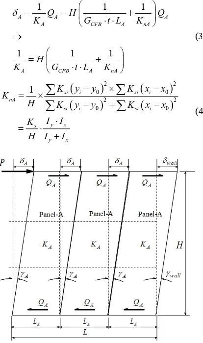
are ith each other at least up to commence of yi el. 3.1. Wall-Type: (SWS) Mechanical Mode
In the type of shear walls without openings, distribution mechanism an
e force ed that ith same shear deform
shown in Figure 13. From equilibrium conditio ternal moment and internal ones,
f ex-
AH
share the same deformation angle,
Wall Wall A A H H
Shear stiffness of panel-A is expressed in equations (3) and (4) in accordance with the sugge Mu-rakami and Inayama [4].
(2)
stion made by
1 1
1 1
A A
A C
A CFB A
Q H
K G
H
K G t L
1 1 A
FB A nA
nA
Q
t L K
K (3)
2 2 0 0 2 2 0 0 si i si i1 si i
nA
si i y x s
y x
K y y K
H
K x x
K y y
I I K
H I I
K x x
(4)
Figure 13. Mechanical models of Wall-Type (SWS) com- posed of three panel-A.
2
20 y i 0
Ix
xix I
y ygidity of CFB (N/mm2),
L ),
where,
CFB
G : Shear ri
t: Thickness of CFB (mm),
A: Length of Panel-A (mm S
K : Slip modulus of nailed-on CF (N/mm),
B with LVL frame
A
K : Total shear stiffness of panel-A (N/mm),
KnA: Partial shear stiffness of panel-A due to nail slip (N/mm),
,
i i
x y : x,y coordinate of i-th nail in Pan ure 8),
el-A (See
Fig-0, 0
x y : Rotational ce (See Figure 8), Finally, relationship between external shear force
nter of Panel-A P and wall rotational angle
wall
is obtained as,
wall Global wall
3 A 3 A A 3 A
P Q K K H
K (5) Gl 3 obal A
K K H. (6) Force acting on i-th nail in x-direction is expressed in
modulus has the same value of Ks;
Equation (7) by assuming each slip
0
0
xi si i x
s i
K y x
p K
y
y y
(7) x-directional rotational angle is expressed in equation (8);
2 0 A x Q H Qg s ysi i K I
K y y
(8)e get;
Combining Equations (7) and (8), w
0
0
A
xi s i
s y
A i
Q H
p K y y
y
K I
Q H y y
(9)
ional force pyi on i-th nail and
ssed as Equations (10) and (11);
I
In the same way, y-direct rotational angle y is expre
0
0
yi si i y
s i y
K x x
p K x x
(10)
2 0 y s x si i Qg QH K IK x x
(11)Combining Equations (10) and (11), we get;
0
0
A i
A
yi s i
s x x
Q H x x Q H
p K x x
K I I
(12)
[image:5.595.74.281.362.712.2]which might give the yielding of nailed-on-sheathing panel, is calculated as Equation (13);
2 2 tan 2 2 0 0 2c resul t xc yc
A i A i
y x
p p p
Q H y y Q H x x
I I I (13)
On the other hand een shear
2
0 0
c c
A
y x
y y x x
Q H I
, the relationship betw force on Panel-A and external force is;
3
A
Q
Therefore, the yielding load of wall-type specimen will be predicted by Equation (15).
P (14)
2 2 0 0 3 c c nail u y x nail u c y xy y x x
PH f I I 2 2 0 0 y c c
3fnail u 3f
P
HZ
y y x x
H
I I
[image:6.595.319.528.85.280.2] (15) where, , c c
Figure 14. Mechanical mode w-Type (SWWOS)
composed of panel-A, panel-B and panel-C.
x y : x,y coordinate of corner nail in Panel-A (mm)
f : Ultimate strength of nailed CFB on
nai
mail u
frame and this value should be determined by
LVL led sin-gle shear joint test (N).
2
20 c 0
y
y y x x
WOS Mechanical M
The mechanical model of shear walls with window open- ings composed of panel-A, B n Figure 14.
Moment equilibrium gives,
A Q gB BQ gC C (16)
Compatibility conditions give,
c c Z I I x
3.2. Window-Type SW odel
and C is shown i
2
PH Q H
Wall Wall B A A C B C B C H H g g (17)
Shear stiffnesses of each panel are,
1 1 A
A A CF
H
Q K G
ls of Windo
1 1 1
B
B B nB
Q K K
(19)
B
CFB B
g
G t L
1 1 1
C
C C CFB C nC
Q K G t L K
.(20)
C
g
1
B t LA KnA
(18)
y x s nA y x I I K K
H I I
(21) y x
s nB
B y x
I I
K K
g I I (22)
y x s nC
C y x
I I
K K
g I I
(23)
shear external force can be expressed as a function of each panel’s stiffness and dimensions as,
From Equations (16) to (20), total P
2 2 2
2
Global wall
A B C C
Global
PK
K H K B K g
K g
H
(24)
At the same time, individual force on each panel can be expressed using global stiffness of total shear wall
shear as follows;
A A A A A A wall A
Global P
Q K K H K H K H
K
(25)
B B B B B B B B wall B B
Global P
Q K K g K g K g
K
(26)
C C C C C C C C wall C C
Global P
Q K K g K g K g
K
(27)
2 2 tan
c resul t xc yc A c
p p p Q HZ
Equations for predicting yielding of each panel (13)
, w used by the corner nail’s ultimate situation, are obtained as,
For Panel-A:
hich might be ca
2 y cA Global Global A cA 2
nail u A cA A
nail u yA
P
f Q HZ K H Z
K
f K
P
K H Z
(28) For Panel-B: 2 y
u B B cB B B cB
Global nail u Global yB
B B cA
P
2
nail
f Q g Z K g Z
K
f K
P
K g Z
(29) For Panel-C: 2 y
nail u C C cC C C c
Global P 2 C nail u yC
C C cC Global
f Q g Z K g Z
K
f K
P
K g Z
ill be pre- o (30).
, ,
(30)
Thus, yielding of window-type shear wall w dicted as the minimum value of equations (28) t
min
y Window
P PyA PyB PyC (31)
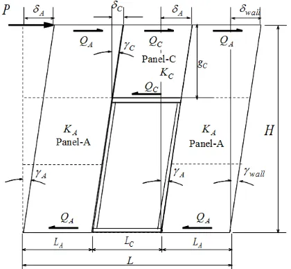
3.3. Door-Type SWDOS
[image:7.595.69.279.513.707.2]For the type of shear walls with door openings, w composed of two panels A, and one panel C, is show Figure 15.
hich is n in
Figure 15. Mechanical models of Door-Type (SWDOS) composed of panel-A and panel-C.
Moment equilibrium gives,
2 Q HA Q gC C
(32) Compatibility conditions PH give, Wall Wall C A A C C
H H g
(33)
Shear stiffnesses of each panel are,
1 1 1
A
A A CFB A nA
H
Q K G t L K
(34)
1 1 1
C
C
C C nC
g
Q K G t L K
CFB C (35) y x s I nA y x I K K
H I I
(36) y x s nC
C y x
I I K K
g I I
(37)
From Equations (32 ear external force P can be expressed as a function of each panel’s stiffness
) to (35), total sh and dimensions as,
2 2
2
Global wall
A C C
Global
PK
K H K
K g
H
(38)
At the same time, individual shear force on each panel can be expressed using global stiffness of total shear wall
as follows;
A A A A A A wall A
Global
P
Q K K H K H K H
K
(39)
C C C C C C C C
Global
P
Q K K g K g
K
(40)
Equations for predicting yielding of each panel, which ght be caused by the corner nail’s ultimate situation, are obtained as,
For Panel-A:
C C wall
K g
mi
2
2
y
nail u A cA A cA
Global
yA
A cA
nail u Global
P
f Q HZ K H Z
K
K H Z
(41)
For Panel-C:
f K
P
2
2 y
nail u C C cC C C cC
Global
nail u Global yC
C C cC
P
f Q g Z K g Z
K
f K
P
K g Z (42)
dicted as the minimum value nd (42
,
of Equations (41) a ).
y Door
P Min PyA PyC
iscussions
a valuated
quivalent t bilinear
ns, mean st results parallel and perpendicular cases was used as a slip
modulu the yielding load of
whole shear wall specimens, lower ultimate nail strength value obtained from perpendicular case was used. These were,
Ks = 1.04 kN/mm, fnail-u = 1.03 kN
(43)
4. Results and D
4.1. Nailed Joint Test
Slip modulus and ultimate strength of single she joint on LVL sheathed with CFB were e
r nailed in ac- cordance with a standard method based on the e
energy approximation principle using perfec relationship [11] as shown in Figure 16 and 17.
For the stiffness calculation of test specime value of initial stiffness estimated from both te on
s, while for the prediction of
0 200 400 600 800 1000 1200 1400 1600
0 5 10 15 20 25
ear fo
rc
e
P
(kN
)
Slip S (mm)
S
h
Nail Joint on LVL-CFB Paralell to the LVL axis
LCBPL-1_1_1.csv LCBPL-2_1_1.csv LCBPL-3_1_1.csv LCBPL-4_1_1.csv LCBPL-5_1_1.csv LCBPL-6_1_1.csv Perfect Bilenear Approximation
(N)
Figure 16. Nail joint on LVL-CFB parallel to the LVL axis.
0 200 400 600 800 o rc e P
(k 1000
1200 1400 1600
0 5 10 15 20 25
S h e a r f N )
Slip S (mm) Nail Joint on
LVL-CFB Perpendicular to the
LVL axis
LCBPP-1_1_1.csv
LCBPP-2_1_1.csv
LCBPP-3_1_1.csv
LCBPP-4_1_1.csv
LCBPP-5_1_1.csv
Perfect Bilenear Approximation
Sh
e
a
r f
N
)
o
rc
e
P
(
Figure 17. Nail joint on LVL-CFB perpendicular to the LVL axis.
parisons Between Static Test Result and
ll three specimens ilure occurred at
member from the , 21, 22, 24, 25. arisons between ob- on angle ( 3
4.2. Com
Predicted Result
The typical damage that occurs in a showed similarities, namely first fa ner nail by tearing off of sheathing LVL member. Shown in Figures 18, 19
Figures 20, 23 and 26 shows comp
[image:8.595.310.535.234.470.2]served load (P)-pure shear deformati ) rela- tionship and predicted results using, Equations (5) and (15) for wall-type (SWS) specimen, Equations (24) and (31) for window-type (SWWOS) specimen and Equation
[image:8.595.311.537.496.716.2]Figure 18. Final condition of shear wall type (SWS).
[image:8.595.59.287.539.706.2]‐20
‐0.08 ‐0.06 ‐0.04 ‐15
‐10 ‐5 0 5 10 15 20 25
‐0.02 0 0.02 0.04 0.06
Shear
fo
rc
e
P
(N)
True shear deformation angle γ3 (rad)
0.08
Wall‐Type SWS
Experimet (P‐γ3): Wall‐Type(SWS)
[image:9.595.58.286.83.282.2]Prediction
[image:9.595.306.535.83.280.2]Figure 20. Comparison between calculation and observation on wall-type (SWS) specimen.
Figure 21. Final condition of shear wall with window type opening (SWWOS).
Figure 22. Falling down of Panel-B from LVL frame. open-ing (SWWOS).
‐25
‐0.08 ‐0.06 ‐0.0 ‐20
‐15 ‐10 ‐5 0 5 10 15 20
4 ‐0.02 0 0.02 0.04 0.06 0.08
Shear
fo
rc
e
P
(N
)
True shear deformation angle γ3 (rad)
Window‐Type SWWOS
Experimet (P‐γ3): Window‐Type (SWWOS)
[image:9.595.331.513.322.494.2]Prediction
[image:9.595.87.257.323.498.2]Figure 23. Comparison between calculation and observation on window-type (SWWOS) specimen.
Figure 24. Final condition of shear wall with window type opening (SWWOS).opening (SWWOS).
[image:9.595.90.256.537.709.2] [image:9.595.367.483.538.708.2](38) and (43) for door-type (SWDOS) specimen,
respec-ms of test WWOD) tural fre-nd it was ecimen as expected. The natural frequency of window-type was 3.86 Hz and it was middle among three and that of door-type was 3.14 Hz and it was the lowest as expected.
tively.
4.3. Dynamic Test Result
Figure 27, 28 and 29 show the spectrum diagra specimens for wall-type (SWD), window-type (S and door-type (SWDOD), respectively. The na quency of wall-type specimens was 4.31 Hz a the highest among three sp
‐20
‐15
‐10
‐5 0 5 10 15 20 25
‐0.08 ‐0.06 ‐0.04 ‐0.02 0 0.02 0.04 0.06 0.08
Sh
e
a
r
fo
rc
e
P
(N)
True shear deformation angle γ3 (rad)
Door‐Type
SWDOS
Experiment ‐γ3) :
Door‐Type )
(P (SWDOS
[image:10.595.318.530.83.282.2]Prediction
Figure 28. Spectrum diagrams of Window Opening-Type (SWWOD) of shear walls.
[image:10.595.58.286.244.445.2] [image:10.595.318.524.321.522.2]rvation Figure 26.Comparison between calculation and obse on door-type (SWDOS) specimen.
Figure 29. Spectrum diagrams of Door Opening-Type
ral frequency f of uation (44)
(SWDOD) of shear walls.
According to a theory [12], natu structure might be calculated using Eq 2π Global (sec
T m K .)
(44) where,
m: Mass of test specimen with machine weight (
1 (Hz) f T
2
N sec m )
Global
K : Global pure shear stiffness of test specimen derived from previous section in which effects of base rotation and bending were not involved (N/m).
The comparisons between calculated natural frequency and that of observed shows on Table 4.
There were some amounts of discrepancies in 32% to Figure 27. Spectrum diagrams of Wall-Type(SWD) of shear
[image:10.595.67.279.500.710.2]d that ies ockin n mea
by ecime enom stant n stop le shake excitation machine suddenly to e the damping coefficient. Damping coefficient estimated for each specimen were 3.7%, 3.3% and 3.6%, respec-tively.
isons between calculated natural frequency
th e
ramet Unit Wall-Typ indow-Type Door-Type
of Table 4. Compar 52% between calculated natural frequency an
measured. A few reasons for these discrepanc be explain due to the effect of bending and r actual test specimens which were involved i
and at of obs rved.
Pa er e W
W
might g of
sured sheath kgf 54.6 49.1 49.1
Wfram kgf 49.1 49.1 49.1
c kgf 67.0 67.0 67.0
otal kgf 7 165.3 165.3
KGlobal kN/rad 5837 4743 3987
KGlobal N/m ,138,095 1,737,180 1,460,444
m N.sec2/m 1675 1621 1621
T sec 0.176 0.192 0.209
F = 1/T Hz 5.69 5.21 4.78
Measured (Hz) 4.31 3.86 3.14
Calculated/Measured 1.32 1.35 1.52
e
Ma hine
T 170.
2
values, while calculated frequency was estimated ing only pure shear stiffness derived on each sp
Figures 30, 31 and 32 show free vibration ph obtained after forced vibration test with a con quency of corresponding natural frequency the portab
us-n.
ena f p
[image:11.595.309.538.111.247.2]re-ing stimate
Figure 30. Free vibration curve Wall-Type(SWD) of shear walls.
[image:11.595.58.552.252.715.2]jected While in the case of
tween experime
.
6. Acknow
IHS
REFERENCES
ractice Periodical on Structural Design struction, Vol. 9, No. 1, 2004, pp. 44-53.
[image:12.595.57.546.66.329.2]doi:10.1061/(ASCE)1084-0680(2004)9:1(44) Figure 32. Free vibrati
5. Conclusion
The mechanical models proposed in this study c dict the behavior of shear walls sub
on curve of Door-Type (SWDOD) of shear walls.
ould pre- to horizontal dynamic nts and
pre-t because push-pull static cyclic load.
loading case, agreements be
diction due to theory was not always sufficien theoretical calculation could only predict pu stiffness of shear wall, while experimentally obser value was thought to involve another effects
re shear ved
ledgements
We would like to express our sincere thanks to Ronpaku program, Laboratory of Structural RISH, Kyoto University, Japan, and R
JSPS for Function, , Ministry of
ity. Public Works of Indonesia for all research activ
[1] J. W. van de Lindt, “Evolution of Wood Sh Testing, Modeling, and Realibility Analysis, B phy,” P
ear Wall ibliogra-
and
[2] C. K. Cheung, R. Y. Itani and A. Polensek, “Characteris- tics of Wood Diaphragms: Experimental and Parametric Studies,” Wood Fiber Science, Vol. 20, No. 4, 1988, pp.
438-456.
[3] R.Y. Itani, R. L. Tuomi and W. J. McCutcheon, “Meth- odology to Evaluate Racking Resistance of Nailed Walls,” Forest Products Journal, Vol. 32, No. 1, 1982,
pp. 30-36.
rmulae to Predict the Shearwall with Any
Structural and
1999, pp. 87-93. -S. Chang and K. all Composed of LVL g,” Journal of Asian
, Vol. 9, No. 2, e.9.463
[4] M. Murakami and M. Inayama, “Fo Elastic and Plastic Behaviour of Nailing Arrangement Pattern,” Journal of Construction Engineering, Vol. 519,
[5] M. Hadi, S. Murakami, A. Kitamori, W. Komatsu, “Performance of Shear W and Cement Fiber Board Sheathin
Architecture and Building Engineering
2010, pp. 463-469. doi:10.3130/jaab
A Simplified Method a Plywood-Sheathed ation of the Racking ,” Journal of the
Ja-39, No. 1, 1993, pp.
A Simplified Method f a Plywood-Sheathed sis of the Shear
Resis-all with Openings,”
Society, Vol. 39, No.
[8] H. Sugiyama and T. Matsumoto, “A Simplified Method a Plywood-Sheathed yses of the Shear Re-sistance of a Wall and of the Strength Behavior of Panel Elements,” Journal of the Japan Wood Research Society, Vol. 40, No. 3, 1994, pp. 280-286.
[9] Y. A. Tjondro and M. Hadi, “Mechanical Properties and Behavior of Falcataria-Rubber Wood LVL,” Proceeding of 19th Australasian, Conference on the Mechanics of Structures and Materials, Chrischurch, New Zealand,
2006.
[10] M. Hadi, S. Murakami and K. Komatsu, “Prediction of Nonlinear Cyclic Behaviors of Shear Wall Composed of [6] H. Sugiyama and T. Matsumoto, “
of Calculating the Shear Strength of Shear Wall with Opening I. Evalu Load of a Shear Wall with Openings
pan Wood Research Society, Vol.
75-79.
[7] H. Sugiyama and T. Matsumoto, “ of Calculating the Shear Strength o Shear Wall with Opening II. Analy tance and Deformation of a Shear W
Journal of the Japan Wood Research
8, 1993, pp. 924-929.
Acacia Mangium Framing and Fiber Cement Board
ng, Vol. 2,
& Beam Construction HOWTEC, 20 Sheathing,” Open Journal of Civil Engineeri
No. 1, 2012, pp. 1-9.
[11] Allowable Design Method for Conventional Wooden Post
08.