Path Planning for Robot Navigation
using View Sequences
Mateus Mendes
∗ †, A. Paulo Coimbra
∗, and Manuel M. Cris´
ostomo
∗Abstract—Navigation based on visual memories is very common among humans. However, planning long trips requires also a more sophisticated represen-tation of the environment, such as a topological map. This paper describes a system that learns paths by storing sequences of images and image information in a Sparse Distributed Memory. Connections between paths are detected by exploring similarities in the im-ages, and a topological representation of the connec-tions is created. The robot is then able to plan paths and skip from one path to another at the connection points. The system was tested under reconstitutions of country and urban environments, and it was able to successfully plan paths and navigate.
Keywords: SDM, Sparse Distributed Memory, Robot Navigation, Path Planning
1
Introduction
About 80 % of all the information humans rely on is vi-sual [1], and the brain operates mostly with sequences of images [2]. View sequence based navigation is also ex-tremely attractive for autonomous robots, for the hard-ware is very straightforward, and the approach is biolog-ically plausible. However, while humans are able to nav-igate quite well based only on visual information, images usually require huge computer processing power. This means that for real time robot operation, visual infor-mation is often avoided. Other sensors, such as sonar or laser range finders provide accurate information at a much lower computational cost.
The goal of equipping robots with cameras and vision-based navigation is still an open research issue. The use of special landmarks (possibly artificial, such as barcodes or data matrices), is a trick that can greatly improve the accuracy of the system [3]. As for the images, there are two popular approaches: one that uses plain images [4], the other that uses panoramic images [5]. Panoramic images offer a 360° view, which is richer than a plain front or rear view. However, this richness comes at the cost of even additional processing power requirements. Some authors have also proposed techniques to speed up
∗ISR - Institute of Systems and Robotics, Dept. of Electrical and
Computer Engineering, University of Coimbra, Portugal. E-mail: [email protected], [email protected]. †ESTGOH, Polytechnic
In-stitute of Coimbra, Portugal. E-mail: [email protected].
processing and/or reduce memory needs. Matsumoto [6] uses images as small as 32x32 pixels. Ishiguro [7] replaced the images by their Fourier transforms. Winters [8] com-presses the images using Principal Component Analysis.
The images alone are a means for instantaneous locali-sation. View-based navigation is almost always based on the same idea: during a learning stage the robot learns a sequence of views and motor commands that, if followed with minimum drift, will lead it to a target location. By following the sequence of commands, possibly correcting the small drifts that may occur, the robot is later able to follow the learnt path. This idea is very simple and it works for single paths. However, for more complex trips, path planning is necessary. To plan paths, skipping from one to another when necessary, more sophisticated rep-resentations of the environment are required. Namely, metric or topological maps can be used [9]. Those maps represent paths and connections between them, making it possible to use algorithms such as A* for intelligent navigation.
This paper explains how view-based navigation is achieved using a Sparse Distributed Memory (SDM) to store sequences of images. The memory is also used to recognise overlaps of the paths and thus establish con-nection nodes where the robot can skip from one path to another. This way, a topological representation of the world can be constructed, and the system can plan paths. Section 2 explains navigation based on view sequences in more detail. Section 3 explains how the SDM works. In Section 4 the robot used is described. Section 5 describes the navigation algorithm, and Section 6 shows and dis-cusses the results obtained.
2
Navigation using view sequences
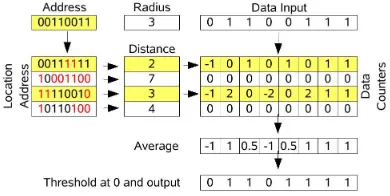
Figure 1: One model of a SDM, using bit counters.
Localisation is estimated based on the similarity of two views: one stored during the learning stage and another grabbed in real-time. The robot tries to find matching areas between those two images, and calculates the hor-izontal distance between them in order to infer how far it is from the correct path. That distance is then used to correct eventual drifts to the left or to the right. This technique is described in more detail in [10].
3
Sparse Distributed Memories
The Sparse Distributed Memory is an associative mem-ory model proposed by Kanerva in the 1980s [2]. It is suitable to work with high dimensional binary vectors. In this case, an image can be regarded as a high dimen-sional vector, and the SDM can be used simultaneously as a sophisticated storage and retrieval mechanism and a pattern recognition tool.
3.1
The original model
The underlying idea behind the SDM is the mapping of a huge binary memory onto a smaller set of physical loca-tions, calledhard locations. As a general guideline, those hard locations should be uniformely distributed in the virtual space, tomimic the existence of the larger virtual space as accurately as possible. Every datum is stored by distribution to a set of hard locations, and retrieved byaveragingthose locations and comparing the result to a given threshold. Figure 1 shows a model of a SDM. “Address” is the reference address where the datum is to be stored or read from. It will activate all the hard lo-cations within a given access radius, which is predefined. Kanerva proposes that the Hamming distance, that is the number of bits in which two binary vectors are different, be used as the measure of distance between the addresses. All the locations that differ less than a predefined number of bits from the input address are selected for the read or write operation.
Data are stored in arrays of counters, one counter for every bit of every location. Writing is done by incre-menting or decreincre-menting the bit counters at the selected addresses. To store 0 at a given position, the correspond-ing counter is decremented. To store 1, it is incremented. Reading is done by averaging the values of all the
coun-Figure 2: Alternative architecture of the SDM, auto-associative and using integers.
ters columnwise and thresholding at a predefined value. If the value of the sum is below the threshold, the bit is zero, otherwise it is one.
Initially, all the bit counters must be set to zero, for the memory stores no data. The bits of the address locations should be set randomly, so that the addresses would be uniformely distributed in the addressing space. There’s no guarantee that the data retrieved is exactly the same that was written. It should be, providing that the hard locations are correctly distributed over the binary space and the memory has not reached saturation.
3.2
The model used
The original SDM model, though theoretically sound and attractive, has some faults. One problem is that of select-ing the hard locations at random in the beginnselect-ing of the operation. Another problem is that of using bit counters, which cause a very low storage rate of about 0.1 bits per bit of traditional computer memory and slow down the system. These problems have been thoroughly described in [11], where the authors study alternative architectures and methods of encoding the data.
To overcome the problem of placing hard locations in the address space, in this work the hard locations are selected using the Randomised Reallocation algorithm [12]. The idea is that the system starts with an empty memory and allocates new hard locations when there’s a new datum which cannot be stored in enough existing locations. The new locations are placedrandomly in the neighbourhood of the new datum address. To overcome the problem of using bit counters, the bits are grouped as integers, as shown in Figure 2. Addressing is done using an arith-metic distance, instead of the Hamming distance. Learn-ing is achieved updatLearn-ing each byte value usLearn-ing the equa-tion:
hkt =h k
t−1+α·(x k
−hkt−1), α∈R∧0≤α≤1 (1)
hk
t is the k th
number of the hard location, at timet. xk
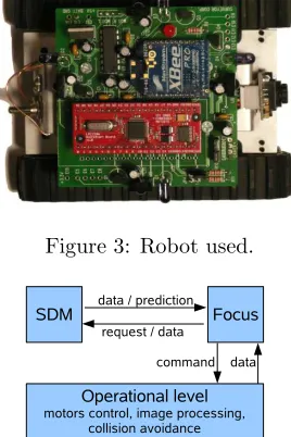
[image:2.595.373.485.72.148.2]Figure 3: Robot used.
Figure 4: Architecture of the implemented software.
4
Experimental Platform
The robot used was a Surveyor1 SRV-1, a small robot
with tank-style treads and differential drive via two pre-cision DC gearmotors (Figure 3). Among other features, it has a built in digital video camera and a 802.15.4 ra-dio communication module. This robot was controlled in real time from a laptop with a 1.8 GHz processor and 1 Gb RAM. The overall software architecture is as shown in Figure 4. It contains three basic modules:
1. The SDM, where the information is stored.
2. The Focus (following Kanerva’s terminology), where the navigation algorithms are run.
3. An operational layer, responsible for interfacing the hardware and some tasks such as motor control, col-lision avoidance and image equalisation.
Navigation is based on vision, and has two modes: su-pervised learning, in which the robot is manually guided and captures images to store for future reference; and au-tonomous running, in which it uses previous knowledge to navigate autonomously, following any sequence previ-ously learnt. The vectors stored in the SDM consist of arrays of bytes, as summarised in Equation 2:
xi=< imi, seq id, i, timestamp, motion > (2)
1http://www.surveyor.com.
In the vector,imiis the imagei, in PGM (Portable Gray
Map) format and 80×64 resolution. In PGM images, ev-ery pixel is represented by an 8-bit integer. 0 is black, 255 is white. seq id is an auto-incremented, 4-byte inte-ger, unique for each sequence. It is used to identify which sequence the vector belongs to. iis an auto-incremented, 4-byte integer, unique for every vector in the sequence, used to quickly identify every image in the sequence.
timestampis a 4-byte integer, storing Unix timestamp. It is not being used so far for navigation purposes. motion
is a single character, identifying the type of movement the robot performed after the image was grabbed.
The image alone uses 5120 bytes. The overhead infor-mation comprises 13 additional bytes. Hence, the input vector contains 5133 bytes.
5
Mapping and planning
The “teach and follow” approachper siis very simple and powerful. But for robust navigation and route planning, it is necessary to extend the basic algorithm to perform tasks such as detection of connection points between the paths learnt and disambiguation when there are similar images or divergent paths.
5.1
Filtering out unnecessary images
During learning in vision-based navigation, not every sin-gle picture has to be stored. There are scenarios, such as corridors, in which the views are very similar for a long period of time. Those images do not provide data useful for navigation. Therefore, they can be filtered out during the learning stage, so that only images which aresufficiently different from their predecessors must be stored. This behaviour can be easily implemented using the SDM: every new image is only stored if there is no image within a predefined radius in the SDM. If the error is below a given threshold, the new image is discarded. A good threshold for this purpose is the memory activa-tion radius. New images that are less than an activaactiva-tion radius from an already stored image will be stored in the same hard locations. They are most probably unneces-sary.
5.2
Detecting connection points
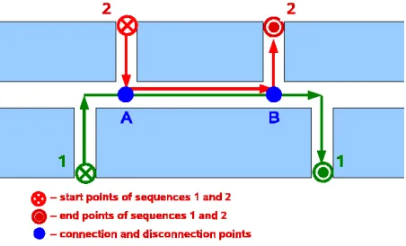
Figure 5: Example of paths that have a common segment. The robot only needs to learn AB once.
the connection points between the known paths. This is a kind of topological representation of the environment.
The main problem with this approach is to detect the con-nection points. The points where the paths come together (point A in Figure 5) can be detected after a reasonable number of images of path 1 have been retrieved, when the robot is learning path 2. When that happens, the robot stores the connection in its working memory and stops learning path 2. From that point onwards, it keeps mon-itoring if it is following the same path that it has learnt. After a reasonable number of predictions have failed, it adds another connection point to the graph and resumes learning the new path. In the tests with the SDM, a number of 3–5 consecutive images within the access ra-dius usually sufficed to establish a connection point, and 3–5 images out of the access radius was a good indicator that the paths were diverging again.
5.3
Sequence Disambiguation
One problem that arises when using navigation based on sequences is that of sequence disambiguation. Un-der normal circumstances, it is possible the occurrence of sequences such as 1) ABC; 2) XBZ; or 3) DEFEG, each letter representing a random input vector. There are two different problems with these three sequences: 1) and 2) both share one common element (B); and one element (E) occurs in two different positions of sequence 3). In the first case, the successor of B can be either C or Z. In the second case, the successor of E can be either F or G. The correct prediction depends on the history of the system. One possible solution relies on using a kind of short term memory.
Kanerva proposes a solution in which the input to the SDM is not the last inputDt, but the juxtaposition of the
lastkinputs{Dt, Dt−1...Dt−k}. This technique is called f olding, andkis the number off olds. The disadvantage is that it greatly increases the dimensionality of the input vector. J. Bose [13] uses an additional neural network, to store a measure of thecontext, instead of adding folds to
the memory.
In the present work, it seemed more appropriate a solu-tion inspired by Jaeckel and Karlsson’s proposal of seg-menting the addressing space [14]. Jaeckel and Karls-son propose to fix a certain number of coordinates when addressing, thus reducing the number of hard locations that can be selected. In the present work, the goal is to retrieve an image just within the sequence that is be-ing followed. Hence, this idea can be applied here. The number of the sequence can befixed, thus truncating the addressing space.
6
Tests and Results
For practical constraints, the tests were performed in a small testbed in the laboratory. This testbed consisted of an arena surrounded by a realistic countryside scenario, or filled with objects simulating a urban environment.
6.1
Tests in an open arena simulating a
country environment
The first test performed consisted in analysing the be-haviour of the navigation algorithm in the open arena. The surrounding wall was printed with a composition of images of mountain views, as shown in Figure 8. The field of view of the camera is relatively narrow (about 40°), so the robot cannot capture above or beyond the wall. Sometimes it can capture parts of the floor.
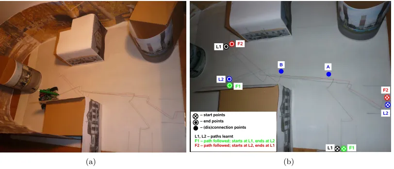
Figure 6 shows an example of the results obtained. In the example, the robot was first taught paths L1 and L2. Then the memory was loaded with both sequences, estab-lishing connection points A and B. The minimum overlap-ping images required for establishing a connection point was set to 3 consecutive images. The minimum number of different images necessary for splitting the paths at point B was also set to 3 consecutive images out of the access radius. The lines in Figure 6 were drawn by a pen attached to the rear of the robot. Therefore, they repre-sent the motion of the rear, not the centre of the robot, causing the arcs that appear when the robot changes di-rection. As the picture shows, the robot was able to start at the beginning of sequence L1 and finish at the end of sequence L2, and vice-versa. Regardless of its starting point, at point A it always defaulted to the only known path L1. This explains the small arc that appears at point A in path F2. This arc represents an adjustment of the heading when the robot defaulted to path L1.
Figure 6: Results: paths taught and followed. The robot successfully skips from one path to another and node points A and B.
the goal of reaching the end of path L2.
6.2
Tests in a simulated urban environment
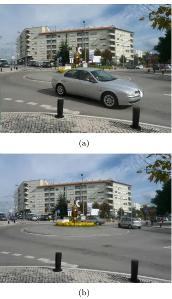
In a second experiment, the scenario was filled with im-ages mimicking a typical city environment. Urban en-vironments change very often. Ideally, the robot should learn one path in a urban environment but still be able to follow it in case there are small changes, up to an accept-able level. For example, Figure 7 shows two pictures of a traffic turn, taken only a few seconds one after the other. Although the remaining scenario holds, one picture cap-tures only the back of a car in background. The other picture captures a side view of another car in foreground.
Due to the small dimensions of the robot, it was not tested in a real city environment, but in a reconstruc-tion of it. Figure 8 shows the results. Figure 8(a) shows the first scenario, where the robot was taught. In this scenario the robot, during segment AB, is guided essen-tially by the image of the traffic turn without the car. In a second part of this experiment the picture of the traffic turn was replaced by the one with the car in foreground, and the robot was made to follow the same paths. Again, it had to start at path L1 and finish at path L2, and vice-versa. As Figure 8(b) shows, it was able to successfully complete the tasks.
7
Conclusions and future work
Navigation based on view sequences is still an open re-search question. In this paper, a novel method was pro-posed that can provide view-based navigation based on a SDM. During a learning stage, the robot learns new paths. Connection points are established when two paths come together or split. This way, a topological represen-tation of the space is built, which confers on the robot the ability to skip from one sequence to another and plan
(a)
(b)
[image:5.595.343.513.362.657.2](a) (b)
Figure 8: Paths learnt (blue and black) and followed, with small scenario changes. The robot plans correctly the routes and is immune to small changes in the reconstituted urban scenario.
new paths. One drawback of this approach is that the SDM model, simulated in software as in this case, re-quires a lot of processing and is very slow to operate in real time. Another disadvantage is that using front views the robot only merges paths that come together in the same heading.
The results shown prove the feasibility of the approach. The robot was tested in two different environments, one that is a reconstitution of a country environment, the other a reconstitution of a changing urban environment. It was able to complete the tasks, even under changing conditions.
References
[1] Steven Johnson. Mind wide open. Scribner, New York, 2004.
[2] Pentti Kanerva. Sparse Distributed Memory. MIT Press, Cambridge, 1988.
[3] Christopher Rasmussen and Gregory D. Hager. Robot navigation using image sequences. InIn Proc. AAAI, pages 938–943, 1996.
[4] Yoshio Matsumoto, Kazunori Ikeda, Masayuki In-aba, and Hirochika Inoue. Exploration and map ac-quisition for view-based navigation in corridor envi-ronment. In Proc. of the Int. Conference on Field and Service Robotics, pages 341–346, 1999.
[5] Yoshio Matsumoto, Masayuki Inaba, and Hirochika Inoue. View-based navigation using an omniview se-quence in a corridor environment. InMachine Vision and Applications, 2003.
[6] Yoshio Matsumoto, Masayuki Inaba, and Hirochika Inoue. View-based approach to robot navigation. In Proc. of 2000 IEEE/RSJ Int. Conference on Intelli-gent Robots and Systems (IROS 2000), 2000.
[7] Hiroshi Ishiguro and Saburo Tsuji. Image-based memory of environment. Inin Proc. IEEE/RSJ Int. Conf. Intelligent Robots and Systems, 1996.
[8] Niall Winters and Jos´e Santos-Victor. Mobile robot navigation using omni-directional vision. In In Proc. 3rd Irish Machine Vision and Image Process-ing Conference (IMVIP’99), pages 151–166, 1999.
[9] J. Meyer. Map-based navigation in mobile robots: Ii. a review of map-learning and path-planning strate-gies. Cognitive Systems Research, 4(4):283–317, De-cember 2003.
[10] Mateus Mendes, Manuel M. Cris´ostomo, and A. Paulo Coimbra. Robot navigation using a sparse distributed memory. In Proceedings of the 2008 IEEE International Conference on Robotics and Au-tomation, Pasadena, California, USA, May 2008.
[11] Mateus Mendes, Manuel M. Cris´ostomo, and A. Paulo Coimbra. Assessing a sparse distributed memory using different encoding methods. InProc. of the 2009 Int. Conference of Computational Intel-ligence and Intelligent Systems, London, UK, July 2009.
[12] Bohdana Ratitch and Doina Precup. Sparse dis-tributed memories for on-line value-based reinforce-ment learning. InECML, 2004.
[13] Joy Bose. A scalable sparse distributed neural mem-ory model. Master’s thesis, University of ester, Faculty of Science and Engineering, Manch-ester, UK, 2003.