Abstract—Robust controller designed by H∞∞∞∞ loop shaping is
complicated and its order is much higher than that of the plant. It is not easy to implement this controller in practical engineering applications. To overcome this problem, we propose an algorithm, GA based fixed-structure H∞∞∞∞ loop shapingcontrol,
to design a robust controller. Genetic algorithm is used to solve the H∞∞∞∞ loop shaping design problem under a structure specified
controller. The performance and robustness of the proposed controller are investigated in a buck-boost converter in comparison with the controller designed by conventional H∞∞∞∞ loop shaping method. Results of simulation demonstrate the advantages of simple structure and robustness against plant perturbations and disturbances of the proposed controller. Experiments are performed to verify the effectiveness of the proposed technique.
Index Terms— H∞∞∞∞ loop shaping , genetic algorithm , buck
boost converter
I. INTRODUCTION
DC-DC converters have been widely used in computer hardware and industrial applications. Controlling of these converters is a challenging field because of their intrinsic nature of nonlinear, time-variant systems [1]. In previous research works, the linear models of these converters were derived by using linearization method [2-3]. Some linear control techniques were applied to these converters based on the linear models [1, 4-5]. NAIM, R., et.al.[4], applied the H∞ control to a boost converter. Three controllers; voltage mode, feed-forward and current mode control were investigated and compared the performance. G.C. loannidis and S.N. Manias [5] applied the H∞ loop shaping control schemes for a buck converter. In their paper, the µ-analysis was used to examine the robust features of the designed controllers. Simone Buso [1] adopted the robust µ-synthesis to design a robust voltage controller for a buck-boost converter with current mode control. The parameter variations in the converter’s transfer function were described in term of perturbations of linear fraction transformations (LFT) class.
In DC to DC converter, normally, the controller is designed by using analog circuit. Although the higher control
Manuscript received January 31, 2008. This work was supported in part by Faculty of Engineering, King Mongkut's Institute of Technology Ladkrabang, Bangkok, Thailand.
Piyapong and Somyot are with the Department of Electrical Engineering, Faculty of Engineering, King Mongkut's Institute of Technology
Ladkrabang, Bangkok 10520, Thailand. Email : [email protected]
Manukid is with the School of Engineering and Technology, Asian Institute of Technology, P.O. Box 4, Klong Luang, Pathumthani 12120, Thailand.
.
techniques mentioned above are powerful techniques for designing the high performance and robust controller; however, the structure of these controllers is complicated with a high order. It is not easy to implement these controllers in the converters. Nevertheless, the design of analog circuit for these controllers is not feasible. To overcome this problem, fixed-structure controller is investigated. Fixed-structure robust controllers have become an interesting area of research because of their simple structure and acceptable controller order. However, the design of this controller by using the analytical method remains difficult. To simplify this problem, the searching algorithms such as genetic algorithm, particle swarm optimization technique, gradient method, etc., can be employed.
Several approaches to design a robust control for structure specified controller were proposed in [6-8]. In [6], a robust H∞ optimal control problem with structure specified controller was solved by using genetic algorithm (GA). As concluded in [6], genetic algorithm is a simple and efficient tool to design a structure specified H∞ optimal controller. Bor-Sen.Chen. et. al.[7], proposed a PID design algorithm for mixed H2/H∞ control. In their paper, PID controller parameters were tuned in the stability domain to achieve mixed H2/H∞ optimal control. A similar work was proposed in [8] by using the intelligent genetic algorithm to solve the mixed H2/H∞ optimal control problem. The techniques in [6-8] are based on the concept of H∞ optimal control which two appropriate weights for both the uncertainty of the model and the performance are essentially chosen. A difficulty with the H∞ optimal control approach is that the appropriate selection of close-loop objectives and weights is not straightforward. In robust control, H∞ loop shaping which is a
simple and efficient technique for designing a robust controller can be alternatively used to design the robust controller for the system. Uncertainties in this approach are modeled as normalized co-prime factors; this uncertainty model does not represent actual physical uncertainty, which usually is unknown in real problems. This technique requires only two specified weights, pre-compensator and post-compensator, for shaping the nominal plant so that the desired open loop shape is achieved. Fortunately, the selection of such weights is based on the concept of classical loop shaping which is a well known technique in controller design. By the reasons mentioned above, this technique is simpler and more intuitive than other robust control techniques. However, the controller designed by H∞ loop shaping is still complicated and has high order. To overcome this problem, in this paper, we propose afixed-structureH∞ loop shaping control to design a robust controller for a buck boost converter. In the proposed technique, the controller structure is firstly specified and the genetic algorithm is then
Fixed Structure Robust Loop Shaping Controller for
a Buck-Boost Converter using Genetic Algorithm
Somyot Kaitwanidvilai, Piyapong Olranthichachat and Manukid Parnichkun
used to evaluate the control’s parameters. Simulation and experimental results show the advantages of simple structure, lower order and robustness of the proposed controller.
The remainder of this paper is organized as follows. Converter dynamics are described in section II. H∞ loop shaping and the proposed technique are discussed in section III. Section IV demonstrates the design example and results. Finally, section V concludes the paper with some final remarks.
II. CONVERTER MODELING
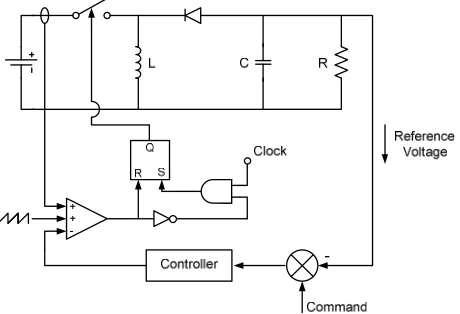
A typical circuit of buck-boost converter with current mode control is shown in Fig. 1. The dynamic model of this converter from the current reference (ir) to output voltage (u0)
is given by [2-3]
) V 2V
V V R C s (1
) V
V V V V R
L s -(1
2
i o
i o L
o i o
i o
L
+ + ⋅ ⋅ ⋅ +
+ ⋅ ⋅ ⋅
+ =
o i
i L r
o
V V
V R di
du (1)
Where RL is the nominal load resistant, Vo is the nominal
output voltage, Vi is the nominal input voltage, L is the
[image:2.612.313.539.78.194.2]inductance of an inductor used in the circuit, C is the capacitance, fswis the switching frequency.
Fig. 1. Buck boost converter with current mode control.
The accuracy of this model has been proved to be accepted, at least in frequency of interest in this application [2-3].
III. H∞ LOOP SHAPING CONTROL AND PROPOSED TECHNIQUE This section illustrates the concepts of the standard H∞ loop shaping control and the proposed technique.
A. Standard H∞ Loop Shaping
H∞ loop shaping control [9] is an efficient method to design a robust controller. This approach requires only a desired open loop shape in frequency domain. Two weighting functions, W1(pre-compensator) and W2(post-compensator),
are specified to shape the original plant Go. In this approach,
the shaped plant is formulated as normalized coprime factor, which separates the plant Gsinto normalized nominator Ns
and denominator Ms factors. Fig. 2 shows the coprime
perturbed plant and robust stabilization used in this approach.
Ns
∆
∆
MsNs +
+
+
-1
− s
M
K
Fig. 2. Co-prime factor robust stabilization problem.
If the shaped plant
G
s=
W G W
2 o 1=
N M
s s−1 , then a perturbed plant is written as [9]1
)
)(
(
−∆
=
N
s+
∆
NsM
s+
∆
MsG
(2)Where ∆Ns and ∆Ms are stable, unknown representing the
uncertainty satisfying
∆
∆
≤
ε
∞Ms
Ns
,
,
ε
is the uncertainty boundary, called stability margin. According to the standard procedure of H∞ loop shaping, the following steps can be applied to design the H∞ loop shaping controller.Step 1 Shape the singular values of the nominal plant Goby
using a pre-compensator W1 and/or a post-compensator W2 to get the desired loop shape. W2 can be chosen as an identity matrix, since we can neglect the sensor noise effect when the use of good sensor is assumed [10]. Weight selection is very important for the design. Typically, weight W1 and W2 are
selected such that the open loop of the shaped plant has the following conflict properties:
• To achieve a good performance tracking, good disturbance rejection, large open loop gain (normally at low frequency range) is required.
• To achieve a good robust stability and sensor noise rejection, small open loop gain (normally at high frequency range) is required.
There are some guidelines for the weight selection in [10]. In SISO system, the weighting functions W1 and W2 can be chosen as
b s
a s K
W W +
+ =
1 and W2 =1 (3) Where K ,w aandb are positive values
Step 2 Minimize ∞-norm of the transfer matrix Tzwover all
stabilizing controllers K, to obtain an optimal cost γopt,as [10]
∞ − −
−
+
=
=
1 1 1)
(
inf
s sstabK opt
opt
I
G
K
M
K
I
ε
γ
(4)εopt << 1indicates that W1 or W2 designed in step 1 are
incompatible with robust stability requirement. If εopt is not
satisfied (εopt << 1), then return to step 1, adjust W1.
Step 3 Select ε < εoptand then synthesize a controller K∞ that
[image:2.612.59.289.347.504.2]( ) 1 1 −1
∞ − − ∞ ∞
∞ + ≤
= s s ε
zw I G K M
K I
T (5)
Controller K∞ is obtained by solving the optimal control problem. See [11] for more details.
Step 4 Final controller (K) follows
K = W1K∞W2 (6)
B. Genetic Algorithm based Fixed-Structure H∞ Loop
Shaping Optimization
The controller, which is derived from H∞ loop shaping method, is complicated and high-order. It is difficult to apply this controller in real works. Nowadays, the fixed-structure robust controller becomes an interesting research area because of their advantages in simple structure and acceptable controller’s order. In this paper, the genetic searching algorithm is adopted to solve this problem. Although the proposed controller is structured, it still retains the entire robustness and performance guarantee as long as a satisfactory uncertainty boundary εis achieved. The proposed algorithm is explained as following.
Assume that the predefined structure controller K(p) has a satisfied parameters p. Based on the concept of H infinity loop shaping, optimization goal is to find parameters p in controller K(p) that minimize infinity norm
T
zw ∞. From (6), the controller K(p) can be written asK(p) = W1K∞W2 (7) Assume that W1 and W2 are invertible, then
K∞ = 11
−
W
K(p)W
2−1 (8) the weight W2 = I which implies that sensor noise is negligibleand not considered [10]. Thus,
K∞ = W1-1 K(p) (9) By Substitution of (9) into (5), then the ∞-norm of the transfer function matrix from disturbances to states,
T
zw ∞, which is subjected to be minimized can be written as∞ − − − −
∞ +
= =
= 1 1 1
1 1
1
cos ( ( ))
)
( s s
zw
t I GW K p M
p K W
I T
J γ
(10) In this paper, GA is adopted to find the optimal control parameters p* in the stabilizing controller K(p) such that the
∞
zw
T
is minimized. The optimization problem can be written asMinimize
∞ − − −
− +
1 1 1
1 1
1
)) ( (
)
(p I GsW K p Ms
K W
I
(11) Subject to
max , min
, i i
i
p
p
p
<
<
Where
p
i,minandp
i,max are the lower and upper bound values of the parameterp
iin controller K(p), respectively.Genetic Algorithms
Our proposed technique uses GA to solve the optimization problem in (11). GA is well known as a biologically inspired class of algorithms that can be applied to any nonlinear optimization problem. This algorithm applies the concept of chromosomes, and the operations of crossover, mutation and reproduction. At each step, called generation, fitness values of all chromosomes in population are calculated. Chromosome, which has the maximum fitness value (minimum cost value), is kept as a solution in the current generation and passed to the next generation. The new population of the next generation is obtained by performing the genetic operators such as crossover, mutation, and reproduction. Crossover randomly selects a site along the length of two chromosomes, and then splits the two chromosomes into two pieces by breaking them at the crossover site. The new chromosomes are then formed by matching the headpiece of one chromosome with the tailpiece of the other. Mutation operation forms a new chromosome by randomly changing value of a single bit in the chromosome. Reproduction operation forms a new chromosome by just copying the old chromosome. Chromosome selection in genetic algorithm depends on the fitness value. High fitness value means high chance to be selected. Operation type selection; mutation, reproduction, or crossover, depends on the pre-specified operation’s probability.
Chromosome in genetic population is coded as binary number. However, for the real number problem, decoding binary number to floating number is applied [12]..
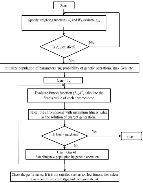
Our proposed algorithm is summarized as
Step1 Shape the singular values of the nominal plant Go by
W1 and W2. Then evaluate the
ε
opt using (4). Ifε
opt< 0.25,then go to step 1 to adjust the weight W1.
Step 2 Select a controller structure K(p) and initialize several
sets of parameters p as population in the 1st generation. Define the genetic parameters such as initial population size, crossover and mutation probability, maximum generation, etc.
Step 3 Evaluate the cost function Jcost of each chromosome
using (10). Assign Jcost = 100, or large number if K(p) does not
meet the constraints in our optimization problem. The fitness value is assigned as
t
J
cos1
. Select the chromosome with minimum cost function as a solution in the current generation. For the first generation, Gen = 1.
Step 4 Increment the generation for a step.
Step 5 While the current generation is less than the maximum
generation, create a new population using genetic operators and go to step 3. If the current generation is the maximum generation, then stop.
Step 6 Check performances in both frequency and time
Gen = 1;
Is Gen = maxGen? Stop
Evaluate fitness function (Jcost)-1, calculate the
fitness value of each chromosome.
Initialize population of parameters (p), probability of genetic operations, max Gen, etc.
Is εopt satisfied?
Yes No
No Yes Start
Gen = Gen +1;
Sampling new population by genetic operation Select the chromosome with maximum fitness value
as the solution of current generation.
Check the performance. If it is not satisfied such as too low fitness, then select
a new control structure K(p) and then go to step 4.
[image:4.612.53.300.47.363.2]Specify weighting functions W1and W2, evaluate εopt
Fig. 3. Flow chart of the proposed design procedure.
IV.SIMULATION AND EXPERIMENTAL RESULTS In this paper, a buck-boost converter designed for a photovoltaic system is studied. Converter’s parameters and considered variation ranges used in this paper are given in Table 1.
Table 1 Converter’s parameters and considered
variation ranges.
Parameter Name Nominal
Value
RL Load Resistant 40 Ω
Vo Output Voltage 30 V
Vi Input Voltage 12 V
L Inductance 100 µH
C Capacitor 470 µF
fsw Switching
frequency
100 kHz
By (1), the nominal transfer function is found to be
72) + (0.7896s
480) + (-0.0042s
=
o
G (12) Both H∞ loop shaping control and our proposed technique are applied to this converter. Firstly, we design a controller by the conventional H∞ loop shaping procedure. In this case,
W
1is selected as1
(s 30) 25
(s 10)
W = +
+ (13)
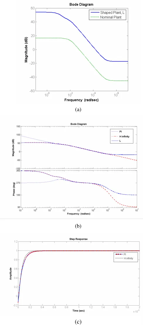
W2 is chosen as 1 since we neglect the sensor noise effect when the use of good sensor is assumed. Fig. 4 (a) shows the plot of open loop shape of nominal plant and shaped plant. As seen in this figure, the bandwidth of the nominal plant is about 600 rad/sec. With these weighting functions, bandwidth of the desired control system is increased to 15,000 rad/sec. Significant performances and robustness improvement are carried out by these weighting functions.
The shaped plant is written as 1 2
(s 30)(-0.0042s + 605.6) 25
(s 10)(0.9963s + 72)
s
G = =L W GW = +
+ (14)
By applying the H∞ loop shaping method, the optimal stability margin (εopt) is founded at 0.708 (γopt =1.4123).
This value indicates that the selected weighting function is compatible with the robust stability requirement. The ε = 0.66123 (γ=1.5123), which is less than the optimal stability margin, is chosen to synthesis the controller. Based on the conventional technique is section II, the conventional H∞ loop shaping controller is synthesized as following
7 6
2 5 3
9 8
2 6 2
1
10 541 . 5 10 386 . 7 10 845 . 1
10 15 . 4 10 763 . 2 10 599 . 4 )
(
x s x s
x s
x s x s
x W
K W s K
+ +
+
+ +
= = ∞
(15)
As shown in (15), the controller is 3th order controller and complicated structure.
Next, PI controller is investigated as a fixed-structure controller. The controller structure is expressed in (16). Kp
and Ki are parameters that will be evaluated.
s K K p
K i
p+
=
)
( (16)
Select the controller parameters, their ranges, and genetic algorithms parameters as following: Kp ∈[0,200],
Ki∈[0,1000], population size = 100, crossover probability
=0.7, mutation probability =0.25, and maximum generation = 30. An optimal solution is obtained after 18 generations. The optimal solution is shown in (17), which has stability margin (ε) of 0.65918(γ=1.5171).
s p
K( )*=21.88+989.7 (17)
Fig. 5 shows plots of convergence of cost function Jcost
[image:4.612.85.288.478.610.2](a)
(b)
[image:5.612.325.529.50.208.2](c)
Fig. 4. (a) Bode plots of the nominal plant and the shaped
plant (desired loop shape, L) (b) The desired loop shape and the loop shape by the conventional H∞ loop shaping and the proposed PI, (c) Step responses by the proposed PI and H∞ loop shaping controllers.
Fig. 5 Cost functions Jcost versus iteration in genetic
algorithm.
The open loop bode diagrams of the nominal and shaped plants are shown in Fig. 4(a). As shown in this figure, at low frequency, the open loop gain of shaped plant is much larger than that of the nominal plant. This makes the designed system has good performance tracking and good disturbance rejection. Open loop bode diagrams are plotted in Fig. 4(b) to verify the proposed algorithm. It is clearly shown that the loop shapes of H infinity control and PI are close to the desired loop shape. Fig. 4(c) shows the step responses of the optimal solutions from the proposed robust PI and the conventional H∞ controllers. As shown in this figure, the settling time of all responses is about 350 µsec.
To verify the robust performance, we change the converter’s parameters as: RL= 10 Ω, Vi = 10.8 V, L=120 µH
and C=611 µF. The designed controller in (15) and (17) is adopted to control this perturbed plant. Obviously, this condition (increase the L and C and decrease the load and input voltage) is worse than the nominal condition. In this case, for simulation, the plant is changed to
70.8) + (0.2938s
129.6) + s (-0.004896
=
G (18) Fig. 6 shows the step responses of all controllers in the perturbed plant. The responses are almost the same as the responses in the nominal plant with some different in the setting time. The results show that the designed system from the proposed controller and H infinity loop shaping has a good performance and robustness.
Fig. 6 Step responses in the perturbed plant.(RL= 10 Ω, Vi =
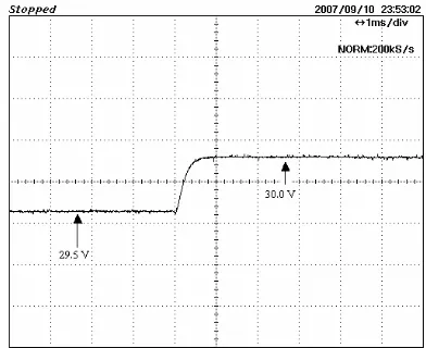
[image:5.612.51.295.55.607.2] [image:5.612.315.548.576.698.2]Some experiments are performed to verify the effectiveness of the proposed controller. The nominal values in Table 1 are used to design a buck boost converter with current mode control. A proposed controller, robust PI controller in (17) is used to control the converter. Fig. 7 shows the experimental result of step response of the proposed controller. The settling time of the response is about 350 µsec. As seen in Fig. 4(c) and Fig. 7, the response of experimental result is almost the same as that of the simulation result.
Fig.7 Step response in the closed loop in nominal conditions for proposed PI controller.
To verify the robust performance of the system, an experiment is performed. The component values and operating points of converter are changed to: RL= 10 Ω, Vi =
10.8 V, L=120 µH and C=611 µF. The controller from the previous experiment is used to control this perturbed plant. The performance is verified by using the step response. As shown in Fig. 8, the step response is almost the same as the response in nominal conditions. This response is over damp response with a small different in the settling time. Experimental results verify that the proposed controller can be applied for the buck-boost converter to achieve a good robust performance.
Fig. 8 Step response in the closed loop in perturbed
conditions for the proposed PI controller.
V.CONCLUSION
Both of H∞loop shaping and the proposed technique can be applied to design a robust controller for a buck boost converter. However, the proposed approach significantly improves in practical control viewpoint by simplifying the controller structure, reducing the controller order and retaining the robust performance. Although the proposed controlleris structured, it still retains the entire robustness and performance guarantee as long as a satisfactory uncertainty boundary ε is achieved. Structure of controller in the proposed technique is selectable. This is desirable, especially in the DC-DC converter which analog circuit is normally used to design the controller. In conclusion, by combining of the approaches, genetic algorithms and H∞ loop shaping; fixed-structure controller design can be designed. Implementation in buck-boost converter assures that the proposed technique is valid and flexible.
ACKNOWLEDGMENT
This research work is financially supported by the Thailand Research Fund (Project. No. MRG4980087) and the research fund from the faculty of engineering, King Mongkut's Institute of Technology Ladkrabang.
REFERENCES
[1] Simone Buso, “Design of a Robust Voltage Controller for a Buck-Boost Converter Using –Synthesis,” IEEE Trans. On Control Systems Technology, Vol. 7, No. 2, pp. 222-229, March 1999. [2] R. B. Ridley, “A new continuous-time model for current-mode
control,” in Power Conversion Intell. Motion (PCIM) Conf. Proc., 1989, pp.455–464.
[3] J. G. Kassakian, M. F. Schlecht, and G. C. Verghese, Principles of Power Electronics. Reading, MA: Addison-Wesley, 1991.
[4] NAIM, R., WEISS, G., and BEN-YAAKOV, S., “H∞ control of boost converters: comparison to voltage mode, feed-forward and current mode controls’. PESC’95, Atlanta, USA, pp. 1327-1332, June 1995. [5] G.C. loannidis, S.N.Manias, “H∞loop-shaping control schemes for the
buck converter and their evaluation using µ-analysis,” IEE Proc.-Electr. Power AppL, Vol. 146. No. 2, March 1999.
[6] Bor-Sen Chenand Yu-Min Cheng, “A Structure-Specified optimal Control Design for Practical Applications: A Genetic Approach,” IEEE Trans. on Control System Technology, Vol. 6, No. 6, November 1998. [7] Bor-Sen Chen, Yu-Min Cheng and Ching-Hsiang Lee, “A Genetic Approach to Mixed H2/ H∞ Optimal PID Control,” IEEE Trans. on Control Systems, p. 51-60, 1995.
[8] Shinn-Jang Ho, Shinn-Ying Ho, Ming-Hao Hung, Li-Sun Shu, and Hui-Ling Huang. Designing Structure-Specified Mixed H2/ H∞
Optimal Controllers Using an Intelligent Genetic Algorithm IGA. IEEE Trans. on Control Systems 2005; 13(6):1119-24.
[9] McFarlane, D.C. & K. Glover, “A loop shaping design procedure using H∞ synthesis,” IEEE Trans. On Automatic Control AC-37 (6):759–769, 1992.
[10] Kemin Zhou, Jhon C. Doyle, 1998. Essential of Robust Control. Prentice-Hall, pp 315-327.
[11] Siguard Skogestad, Ian Postlethwaite, Multivariable Feedback Control Analysis and Design. John Wiley & Son, pp.118,376-380, 1996.
[image:6.612.82.278.161.321.2] [image:6.612.85.286.521.688.2]