A Parallel Processor Based Frequency and Spatial Adaptive Image Coder
Ganesh Sayee ramakrishnan, Venkatraman Sayee ramakrishnan, Avinesh D, Raghunath R, John Anand MABSTRACT
We present frequency and spatial adaptive packet wavelet coder implemented with Cellular Neural Network architecture. This paper also demonstrates how the cellular neural universal machine (CNNUM) architecture can be extended to image compression. The packet wavelet coder performs the operation of image compression, aided by CNN architecture. It uses the highly parallel nature of the CNN structure and its speed outperforms traditional digital computers. In packet wavelet coder, an image signal can be analyzed by passing it through an analysis filter banks followed by a decimation process, according to the rules of packet wavelets. Traditional packet decomposition adapts to a global frequency distribution, this technique finds the best joint of spatial segmentation and local frequency basis. The Simulation results indicate that the quality of the reconstructed image is superior by using frequency and spatial adaptive packet wavelet coding scheme
KEY WORDS
Cellular neural networks, Image coding, packet wavelets, spatial segmentation, parallel processing, PSNR.
1. Introduction
The wavelet coding method has been recognized as an efficient coding technique for lossy compression. The wavelet transform does a good job of de-correlating image pixels in practice, especially when images have power spectra that decay approximately uniformly and exponentially.
Ganesh Sayee ramakrishnan is an UG student in Sri Venkateswara College of Engineering,India.(email: [email protected]).
Venkatraman Sayee ramakrishnan is an UG student in Sri Venkateswara College of Engineering,India.(email: [email protected]).
Avinesh D is an UG student in Sri Venkateswara
College of Engineering,India.(email: [email protected]).
Raghunath R is an UG student in Sri Venkateswara College of Engineering,India.
(email: [email protected]).
John Anand M is an UG student in Sri Venkateswara College of Engineering,India.
(email: [email protected]).
On the other hand Cellular neural networks (CNN) is a analog parallel-computing paradigm defined in space and characterized by locality of connections between processing elements such as cells or neurons .A CNN principal property is the ability to perform massive processing and such property fits perfect in image processing tasks where minimum processing time is demanded. In this paper we have presented frequency and spatial adaptive packet wavelet coder using CNN architecture and compared the results to that of pyramidal wavelets using CNN architecture. Packet wavelets allow the option to zoom in to high frequencies if we like, by analyzing at each level only the band with highest energy. The signal passes through filter banks, and it is sampled following the packet wavelet coder.
By including spatial segmentation in the search for the most efficient basis for representation, image decomposition via adaptive wavelets packets adapts to image non-stationarity as well as local frequency content. When fixed spatial decomposition is performed, the effect of non-stationarity can be avoided.
In order to implement image coder using CNN, the kernels considered are the templates defined in the CNN mathematical representation. The image is passed through the CNN, which performs filtering operation. Image reconstruction is performed by inverse wavelet transform. The kernels for inverse wavelet transform are also treated as templates. In our work, we have used Quadrature mirror filters (QMF) coefficients for filtering operation.
2. Cellular Neural Networks
using CNN and its highly parallel nature makes its speed outperform traditional digital solutions.
Defining Equations of CNN [1][2] State equation:
( , ) (, ) ( , ) (, )
(, ; , )
(, ; , )
...(1)
r r
o
ij ij kl kl ij
Ckl S i j Ckl S i j
x
x
Ai j kl y
Bi j kl u z
∈ ∈
= − +
∑
+
∑
+
The Output Equation:
1
1
( )
1
1 ...(2)
2
2
ij ij ij ij
y
=
f x
=
x
+
−
x
−Where
x
ij∈
R y
, ,
kl∈
R u
kl∈
R and z
ij∈
R
are called state output, input and threshold of cell C(i,j) respectively. A(i,j;k,l) and B(i,j;k,l) are called the feedback and input synaptic operators .A CNN belongs to the zero-feedback class C(0,B,Z) if and only if all feedback template elements are zero i.e., A≡0.
Each cell of a zero feedback CNN is described by
[image:2.612.322.518.275.603.2]The system structure[2] of a cell C( i,j). U denotes the input from the surrounding cells. In this case, there is no feed-back and no coupling from the outputs of the surround cells. It is shown in Fig. 1.
Fig 1.Zero feedback (feed-forward) CNN
3.
Frequency and Spatially Adaptive
Packet
Wavelet representation for Images
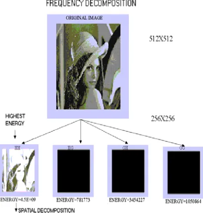
Images are 2-D signals. An image can be analyzed by passed it through four different combinations of low and high pass filter. At each level of resolutions, instead of splitting the signal in to two components, it can be split in to four. A schematic representation of such analysis is shown in Fig.3. This is known as Packet wavelet representation. The tree we construct this way is called spatially adaptive tree structure [3]. Zooming into a frequency band with a packet wavelet transform may be achieved by preferentially expanding a chosen band at each level of resolution. It is a usual practice that one chooses the band, which contains the maximum energy. The energy of a band is computed by adding the squares of the values of the individual pixels. In the method used, the band with maximum energy at each
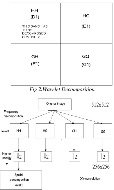
level of decomposition is chosen and it is further decomposed into its constituent sub-bands. Here the original image is decomposed using four filters (filter banks) HH, HG, GH and GG in to four bands. We obtain four bands D1, E1, F1 and G1. Then the band with highest energy is chosen and decomposed spatially. Suppose, HH has the highest energy it is decomposed spatially. The spatial decomposition is carried using a quad tree split. Since the spatial partitions do not overlap, this segmentation allows the four children nodes to be analysed independently. The flowchart for spatial decomposition is shown in Fig.5 .The approximate commutativity of spatial and frequency decompositions is shown Fig.6.
The general wavelet decomposition is shown below in Fig 2.
Fig 2.Wavelet Decomposition
Fig 3.A Schematic representation of the Decomposition process
[image:2.612.77.262.433.536.2]
representation of the reconstruction Process is shown in Fig.4.
Fig.4 A schematic representation of the reconstruction process
Fig.5 Flowchart for spatial decomposition
Fig.6 Spatial and frequency decomposition
4.Frequency and Spatially Packet Wavelet
Coder in the CNN Computer
The Packet Wavelet scheme represented in the Figure.2 can be implemented in the CNN computer. The 2D Haar Wavelet has been used implemented in the CNN universal machine, wherein each convolution block is modeled according to [1][2],
… ………… (4)
Boundary conditions are stated according to a periodic representation, where r, the neighbourhood distance is set to unity and DA, DB, the offsets are set to zero. The possibility of electrical saturation in to the CNN chip is controlled by the non –linear function g (xe).
In order to perform the Wavelet transform with the CNN chip, the relationship templates[2] are:
When reconstruction is performed, conditions stated for direct transform are preserved. We only change the B templates [1][2], which will be;
For spatial decomposition and reconstruction, local horizontal(vertical) averaging of the base image is done by the following templates. It replaces each pixel by an estimation based on the average of the neighbouring cells using one of the following templates
Simulation Results
of decomposition are recorded for all the images. The compression ratio achieved for the entire test image is equal to 4:1. The concept of packet wavelet transform is implemented in such a way that, at each iteration, the energy of the four bands are calculated. The sub-band with maximum energy is now taken out and spatial decomposition is performed on that particular sub-band . For example the Barbara test image contains a narrow band component at high frequencies. Fingerprint images also contain similar narrow band high frequency components. Table- 2 shows the energy calculations for the different sub bands in the standard test images considered.
[image:4.612.326.535.101.454.2]The reconstruction for images that contain narrow band frequency components using packet wavelet transform shows improved quality than that of the pyramidal structured wavelets[3][4][5].This is very clearly seen by our simulation results. Convolution is performed at each compression level and the tempering matrices used are remaining unchanged. Similarly, the matrices used for de-convolution are also shown. All simulations are carried out for the case of 2D-Haar wavelet transform. The frequency decomposition and reconstruction is shown in Fig 7 and Fig 10. The spatial decomposition and reconstruction is shown Fig 8 and Fig 9
Fig.7 Frequency decomposition
Fig 8 Spatial decomposition
Fig.9 Spatial Reconstruction
Fig 10 Frequency reconstruction
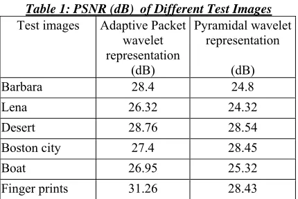
[image:4.612.93.297.368.582.2]Table 1: PSNR (dB) of Different Test Images Test images Adaptive Packet
wavelet representation
(dB)
Pyramidal wavelet representation
(dB)
Barbara 28.4 24.8
Lena 26.32 24.32
Desert 28.76 28.54
Boston city 27.4 28.45
Boat 26.95 25.32
Finger prints 31.26 28.43
4. Conclusions
We have presented a new algorithm for image compression using spatially and frequency adaptive packet wavelet implemented with the Cellular Neural Network architecture. This approach adapts jointly to the image spatial and frequency distributions. The idea is to exploit CNN characteristics along with the frequency adaptive nature of the packet wavelet transform. From the simulations results and image reconstruction on various test images, we can say that high compression rates and high visual quality are possible for images that contain narrow band frequency components. Also the visual quality is better than pyramidal wavelets using CNN. This is an attempt to disseminate the application of CNN in the field of image compression. Though various other methods have been developed for image compression, still it's unconquered using CNN.
References
[1] L.O Chua and L.Yang,”Cellular Neural Networks: Theory”, IEEE Transactions on circuits syst, 35, 1988, 1257-1272.
[2] Leon O.Chua and Tamas Roska, Cellular neural networks and visual computing,foundations and applications (Cambridge university press)
[3] Mario Petrou, Pedro Garcia, Image processing, Dealing with textures( Wiley Edition).
[4] S.G Mallat, “Theory for Multi resolution signal decomposition: The wavelet representation”, IEEE Trans on PAMI, Vol.11, No.7, pp.674-693, June 1989.