Abstract— The problem of laminar natural convection heat transfer from a fin array containing a vertical base and horizontal fins is theoretically formulated by treating the adjacent internal fins as two fin enclosures. The governing equations of mass, momentum and energy balance for the fluid in the two fin enclosure together with the heat conduction equations in the fins are numerically solved using ADI method. The heat transferred to the ambient fluid from the two end fins is also computed separately. Heat transferred by radiation is considered in the analysis. The numerical results are compared with the experimental data available in literature. The effects of system parameters such as base temperature, fin height, fin spacing on heat transfer rate from the fin array are studied.
Index Terms— Fin array - Natural convection, Heat transfer, Horizontal fins, Radiation, Vertical base.
I. INTRODUCTION
Extended surfaces, which are popularly known as fins, are extensively used in air-cooled automobile engines and in air-cooled aircraft engines. Fins are also used for the cooling of computer processors, and other electronic devices. In various applications heat from the fins is dissipated by natural as well as forced convection and radiation. Fins are used as arrays in all the applications. The natural convection heat transfer from horizontal and vertical fin arrays is studied by a number of investigators. Starner and McManus [1] conducted an experiment on multi fin array positioned with the base horizontal, 450 and vertical. They found that 450 array heat
transfer coefficients results 5 to 20% below those of the vertical array. Acharya and Patankar [2] did an analytical study to find
Manuscript received May 12, 2007. The financial assistance received under SAP/DSA program of the Department of Chemical engineering and TEQIP College of Engineering is great fully acknowledged
S. V. Naidu is with the Department of Chemical Engineering, Andhra University, Visakhapatnam-530003, India. (phone: +91 891 2844893, fax: +91 0891 2719788; e-mail: [email protected])
V. Dharma Rao is with the Department of Chemical Engineering, Andhra University, Visakhapatnam-530003, India. ([email protected])
B. Govinda Rao is with the G. V. P. College of Engineering, Visakhapatnam-41, India.([email protected])
K. V. Sharma is with the Centre for Energy Systems, JNTU College of Engineering, Kukatpally, Hyderabad, India.(e-mail: [email protected])
the effect of buoyancy on laminar mixed convection in a shrouded fin array. Harahap and McManus [3] conducted an experimental investigation on natural convection heat transfer from horizontal fin arrays. They found that the heat transfer coefficients for horizontal fin channels are lower than the heat transfer coefficients for vertical fin channels. Jones and Smith [4] suggested an optimum arrangement for maximum heat transfer from rectangular fins on horizontal surfaces. Donvan and Roher [5] reported the fin temperature distribution, the local radiative heat transfer, the total convective heat transfer and the effectiveness of the fins. Van de pol and Tierney [6] conclude from their study that the vertical base plate/vertical fin channel configuration shows the best performance for natural cooling. Bar-Cohen [7] studied on fin thickness for an optimized natural convection array of rectangular fins. Elenbaas [8] presented the article on heat dissipation of parallel plates by natural convection. He concluded that in the limit of small gap width, Nusselt number is proportional to Rayleigh number. Van de pol and Tierney [9] studied the free convective Nusselt number for U – shaped channels. They developed a mathematical relation ship for laminar flow heat transfer from constant temperature U – shaped channels. Bilitzky [10] studied the vertical base plate and horizontal fin arrays for the parameters like fin length vs total heat dissipated if the fins on one side of sink and non finned side of sink was adiabatic. He reported that vertical base and horizontal fin array having less heat dissipation than vertical base and vertical fin array.Prakash and Lounsbury [11] numerically analysed the problem of laminar fully developed flow in finned parallel plate passage. They considered number of cross sectional shapes of the fin and studied the effect fin shape on various system parameters, friction factor and Nusselt number etc. They conclude that rectangular fins gives maximum heat transfer followed in decreasing order by the convex – parabolic, triangular and concave parabolic fins. Lakhal et. al [12] numerically studied the natural convection heat transfer in inclined enclosures with perfectly conducting fins attached to the heated wall. They reported that heat transfer through the cover is considerably effected by the presence of the fins. They proposed some correlations for practical applications. Yuncu and Anbar [13] conducted experiments by mounting different numbers of fins on a heated horizontal base plate of width 250 mm. The fin spacing decreased as the number of fins was increased. They
Combined Convection and Radiation Heat
Transfer from a Fin Array with a Vertical
Base and Horizontal Fins
found that for a given base–to–ambient temperature difference the convection heat transfer rate from arrays reaches a maximum at a particular fin spacing and fin height. Rao et.al. [14] developed a numerical model treating the adjacent internal fins as two-fin enclosures for study the heat transfer from horizontal fin array. They studied the effects of system parameters like fin height, fin spacing, base temperature and emissivity on rate of heat transfer from fin array. Regression equations are also developed to readily calculate the average Nusselt number, heat transfer rate and effectiveness for a fin array. Rammohan Rao and Venkateshan [15] conducted experiments on horizontal fin arrays. They studied the effects of fin height, fin spacing, fin array base temperature and, fin emissivity on heat transfer rates from fin array.
A survey of literature reveals most of the experimental and theoretical studies on horizontal fin array (horizontal base and vertical fins) and vertical fin arrays (vertical base and vertical fins). Only a very few studies on vertical base and horizontal fins in a fin array. Hence the problem of natural convection and radiation heat transfer from a vertical base and horizontal fins in a fin array is theoretically formulated. Separate analysis is also done for end fins in the fin array for getting the heat transfer rates.
II. PHYSICAL MODEL AND FORMULATION
The two adjacent internal fins having a common base are shown in Fig. 1. The base is maintained at a constant temperature Tw,0, and Tw,0>
T
∞ , whereT
∞ is ambient airtemperature. The space between the fins S is in y - direction. The length L of each fin is in x – direction. The half-thickness of the fin is tF. Heat is transferred from the fins and the base to
the ambient air by convection and radiation.
The problem is formulated by considering the two horizontal fins and the vertical base together as a two-dimensional enclosure. The velocity and temperature fields in the two-fin
enclosure are governed by the mass, momentum and energy balance equations for the fluid in conjugation with the one-dimensional heat conduction equation for each fin, which are given below. Thus the equations considered are as follows. Fluid medium
x
u
∂
∂
+
∂
∂
y
v
= 0 (1)ρf
⎟⎟
⎠
⎞
⎜⎜
⎝
⎛
∂
∂
+
∂
∂
+
∂
∂
y
u
v
x
u
u
t
u
=-x
p
∂
∂
+μf
⎟⎟
⎠
⎞
⎜⎜
⎝
⎛
∂
∂
+
∂
∂
2 2 2 2y
u
x
u
(2) ρf⎟⎟
⎠
⎞
⎜⎜
⎝
⎛
∂
∂
+
∂
∂
+
∂
∂
y
v
v
x
v
u
t
v
= -
∂
∂
y
p
-ρ
f[
1
−
β
(
T
−
T
∞)
]
g
+ μf
⎟⎟
⎠
⎞
⎜⎜
⎝
⎛
∂
∂
+
∂
∂
2 2 2 2y
v
x
v
(3)ρf Cpf
⎟⎟
⎠
⎞
⎜⎜
⎝
⎛
∂
∂
+
∂
∂
+
∂
∂
y
T
v
x
T
u
t
T
= kf
⎟⎟
⎠
⎞
⎜⎜
⎝
⎛
∂
∂
+
∂
∂
2 2 2 2y
T
x
T
+
q
′′′
(4) whereq
′′′
= (2 W L qr1 + S W qr3) / (S W L);qr1 = (Eb1 - J1) / R1 and qr3 = (Eb3 - J3) / R3
where R1 = (1 - ε1) / ε1; R3 = (1 - ε3) / ε3 (Rao et. al., [15])
Heat conduction in bottom fin
ρw Cpw
t
T
w∂
∂
= kw 2w 2
x
T
∂
∂
+ wA
P
kf 0 yy
T
=∂
∂
(5) Heat conduction in top finρw Cpw
t
T
w∂
∂
= kw 2 w 2
x
T
∂
∂
- wA
P
kf S yy
T
=∂
∂
(6) where P and Aw are the half perimeter and half cross-sectionalarea of the fin respectively. P = 2 tF + W and Aw = tF W
The u- and v- momentum balance equations, i.e., Eqs. (2) and (3) are coupled making use of vorticity ζ, which is defined as follows.
x
v
y
u
∂
∂
−
∂
∂
=
ζ
(7) Vorticity equation.⎟⎟
⎠
⎞
⎜⎜
⎝
⎛
∂
∂
+
∂
∂
+
∂
∂
−
=
⎟⎟
⎠
⎞
⎜⎜
⎝
⎛
∂
∂
+
∂
∂
+
∂
∂
2 2 2 2 f f fy
ζ
x
ζ
μ
y
T
β
g
ρ
y
ζ
v
x
ζ
u
t
ζ
ρ
- (8)
The vorticity equation in terms of stream function and stream function ψ is defined as
2 2 2 2
y
x
∂
ψ
∂
+
∂
ψ
∂
=
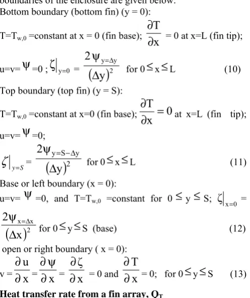
The boundary conditions at the left, right, bottom and top boundaries of the enclosure are given below.
Bottom boundary (bottom fin) (y = 0): T=Tw,0 =constant at x = 0 (fin base);
x
T
∂
∂
= 0 at x=L (fin tip);
u=v=
ψ
=0 ;ζ
y=0 =( )
2 y yy
2
Δ
ψ
=Δfor 0
≤
x≤
L (10) Top boundary (top fin) (y = S):T=Tw,0 =constant at x=0 (fin base);
x
0
T
=
∂
∂
at x=L (fin tip); u=v=
ψ
=0;S y=
ζ
=( )
2 y S yy
2
Δ
ψ
= −Δfor 0
≤
x≤
L (11) Base or left boundary (x = 0):u=v=
ψ
=0, and T=Tw,0 =constant for 0≤
y≤
S;ζ
x=0 =( )
2 x xx
2
Δ
ψ
=Δfor 0
≤
y≤
S (base) (12) open or right boundary ( x = 0):v =
∂
∂
u
x
=∂
∂
ψ
x
=∂
∂
x
ζ
= 0 and∂
∂
T
x
= 0; for 0≤
y≤
S (13)Heat transfer rate from a fin array, QT
The rate of heat transfer from the left or right fin Q1, base Q3
and end fin Q5 are calculated using the related equations. The
height of the vertical base plate, on which the fins are horizontally mounted, is given by
H = (N - 1) S + 2 N tF (14)
where B is the breadth of the plate and N is the number of fins.
Q1 =
(
)
⎥
⎦
⎤
⎢
⎣
⎡
−
+
⎥
⎦
⎤
⎢
⎣
⎡
∂
∂
−
(
LW
)
R
J
E
)
LW
(
y
T
k
1 1 1 b f ;Q3 =
(
)
⎥
⎦
⎤
⎢
⎣
⎡
−
+
⎥⎦
⎤
⎢⎣
⎡
∂
∂
−
(
SW
)
R
J
E
)
SW
(
x
T
k
1 3 3 3 bf (15)
Separate analysis is done for the end fins in the fin array.
Q5 =
(
)
⎥
⎦
⎤
⎢
⎣
⎡
−
+
⎥
⎦
⎤
⎢
⎣
⎡
∂
∂
−
(
LW
)
R
J
E
)
LW
(
y
T
k
1 1 1 bf (16)
The heat transfer rates from the inner fins of the fin array (QI),
the base of the fin array (QB) and the two end fins (QE) are
given by
QI = 2 (N - 2) Q1, QB =Q3 , QE = 2 Q5 (17)
QT, the total heat transfer rate from the fin array is given by
QT = QI + QB + QE
Fin array – average Nusselt number, Num
Total heat transfer area for the N-fin array is given by AT = (H – 2 N tF) W + 2 N L (W+2 tF) (18)
The average heat transfer coefficient, hm for the N-fin array for
combined convection and radiation is defined by the following equation
hm =
(
T
−
T
∞)
A
Q
0 , w TT (19)
The average Nusselt number for the N-fin array is defined as Num = hm S / kf (20)
III. METHOD OF SOLUTION
The temperature fields in the two-fin enclosure and on the fins are obtained from the solution of the normalized energy balance equation for the fluid in conjunction with the heat conduction equations for fins. Alternating Direction Implicit (ADI) method (Roache [16]) is used to solve the energy balance equation for the fluid. The solution of these equations yields temperature and vorticity fields at all grid points in the enclosure at each time step. Stream functions are obtained from the vorticities by Successive Over Relaxation (SOR) method. The normalized velocity components at all grid points are calculated making use of the stream function definitions. The procedure is continued for successive time steps until steady temperature and velocity fields are obtained at all grid points in the two-fin enclosure.
IV. RESULTS AND DISCUSSION
The obtained numerical results are compared with the experimental data available in literature for validation of the present theoretical model. Experimental data of Bilitzky [10] for a-fin array is shown in Fig. 2. Numerical results are obtained for S = 7.5 mm, for L =10, 20, 30 ,40 and 50 mm; W = 100 mm for ε1 = 0.1 and for Tw,0 = 80oC. The properties and
other data used are as follows: kw = 205 W m-1 K-1, ε3 = 0.15, tF
= 0.75 mm, H = 100 mm and
T
∞= 30oC. These results areshown plotted in Fig.2 along with the experimental data of of Bilitzky [10]. A good agreement is observed between the numerical results and the experimental data. Fig. 3 presents the variation of convection heat transfer rates from fin array with fin spacing and effect of base temperature of the fin array. The numerical results are shown in Fig.3 for fin length L = 25 mm, W = 100 mm, H = 250 mm, for fin base temperatures 50, 75 and 100OC. It is observed from Fig. 3 that with decreasing of fin
spacing heat transfer rates are increasing sharply. Fig 3. also shows that convective heat transfer rates from a fin array are increasing with increasing of base temperature of the fin array at all fin spacings. Fig. 4, shows the Variation of convective heat transfer rates from fin array with fin spacing and effect of fin length. Numerical results are obtained for L = 15, 25 and 50 mm, for W = 100 mm, H =250 mm, TW,0 = 50OC . It is observed
[image:3.595.46.294.102.397.2]from Fig. 4, that convective heat transfer rates from a fin array are increasing with increasing of fin length at all fin spacings. Fig. 5 shows variation of average Nusselt number of fin array with Raleigh number. Numerical data obtained for L = 15, 25 and 50 mm, for TW,0 = 50 to 100OC, for fin spacings, S = 7.3,
V. CONCLUSIONS
1. A theoretical model is postulated to tackle the problem of heat transfer from a vertical fin array. According to the model, the fin array is assumed to be formed by joining two successive fin as an enclosure.
2. The problem for the case of a two-fin enclosure is theoretically formulated and solved considering heat transfer by natural convection and radiation.
3. The problem for the case of a single fin is also formulated and solved to account for the heat loss from end fins in the array.
4. Making use of the numerical results for the two-fin enclosure and those for the single fin, a procedure is outlined to assess the total heat transfer rate, average Nusselt number and effectiveness for a fin array. The effect of the system parameters, such as fin spacing, number of fins, fin height, fin base temperature is studied on the total heat transfer from the fin array.
5. A comparison with the experimental data existing in literature indicates satisfactory agreement.
V. REFERENCES
[1] K.E. Starner, Jr. McManus, “An experimental investigation of free convection heat transfer from rectangular fin arrays,” J. Heat Transfer vol. 85, 1963,
pp. 273 – 278.
[2] S.Acharya, S.V. Patankar, “Laminar mixed convection in a shrouded fin array,” ASME J. Heat Transfer, vol. 103,
1965, pp. 559 - 565.
[3] F. Harahap, H.N. Mc Manus, “Natural convection heat transfer from horizontal rectangular fin arrays,” ASME J. Heat transfer,” vol. 89, 1967, pp. 32-38.
[4] Charles D. Jones, Lester. F. Smith, “Optimum arrangement of rectangular fins on horizontal surfaces for free convection heat transfer,” ASME Journal of Heat Transfer, vol. 92, 1970, pp. 6 – 10.
[5] R.C. Donvan, W.M. Roher, “Radiative and convective conducting fins on a plane wall, including mutual irradiation,” ASME J. Heat Transfer, vol. 93, 1971,
pp. 41-46.
[6] D.W. Van de pol, J.K.Tierney, “Free convective heat transfer from vertical fin arrays,” IEEE Trans, PHP – 10
(4), 1974, pp. 267- 271.
[7] A. Bar – Cohen, “Fin thickness for an optimized natural convection array of rectangular fins,” ASME Journal of Heat Transfer, vol. 101, 1979, pp. 564 – 566.
[8] W. Elenbass, “The heat dissipation of parallel plates by free convection,” Physica, vol. 9, 1942, pp. 1 - 28.
[9] D.W. Van de pol, J.K.Tierney, “Convection Nusselt number for vertical shaped channels, Journal of Heat transfer,” vol. 95, 1973, pp. 542 – 543.
[10] A.Bilitzky, “The effect of geometry on heat transfer by free convection from fin array,” MS Thesis, Dept. of Mechanical Engineering, Ben – Gurion University of the Negev, Beer Sheva, Israel. 1986.
[11] C.Prakash and R.Lounsbury, “Analysis of laminar fully developed flow in a plate fin passages; effect of fin shape,”
Journal of Heat Transfer,” vol. 108, 1986, pp. 693 – 697.
[12] E.K. Lahal, M. Hasnaoui, E. Bilgen and P. Vasseur, “Natural convection in inclined rectangular enclosures with perfectly conducting fins attached on the heated wall,” Heat and Mass Transfer, vol.32, 1997, pp. 365 –
373.
[13] H.Yuncu and G. Anbar, “An experimental investigation on performance of fins on a horizontal base in free convection heat transfer,” Springer – Verlag Heidelberg,
Heat and Mass Transfer, vol. 33, 1998, pp. 507 – 514.
[14] V.Dharma Rao, S.V. Naidu, B. Govinda Rao and K.V. Sharma, “Heat transfer from horizontal fin array by natural convection and radiation – A conjugate analysis,” Int. J. Heat and Mass Transfer, vol. 49, 2006, pp. 3379 – 3391.
[15] Ram Mohan Rao, S.P. Venkateshan, “Experimental study of free convection and radiation in horizontal fin arrays,”
Int. J. Heat Mass Transfer, vol. 39, 1996, pp. 779 – 789.
[16] P.J. Roache, “Computational Fluid Dynamics, Hermosa, Albuquerque,” N.M 1985.
VI. NOMENCLATURE
AB area of the horizontal base plate, (B W), m2
AR aspect ratio for two-fin enclosure, (L/S)
Aw half the cross-sectional area of the fin, (tF W), m2
Cp specific heat, J kg-1 K-1
E Effectiveness F radiation shape factor
g acceleration due to gravity, m s-2
Gr Grashof number,
g
β
(
T
w,0−
T
∞)
S
3/
ν
f2 H Height of the vertical base plate, m h heat transfer coefficient, W m-2 K-1J radiosity, W m-2.
k thermal conductivity, W m-1 K-1
L length of fin , m
M fin parameter, kf P S Gr1/4 /(kw Aw)
N number of fins in the fin array NR Radiation parameter,
(
)
1/40 , w f
4
Gr
1
T
T
k
S
T
∞ ∞
−
σ
p pressure, Pascals
P half-perimeter of the fin, (2 tF + W), m
Pr Prandtl number, cpf μf / kf
Q heat transfer rate, W
Ra Rayleigh number, g β (Tw,0 -
T
∞) S3 / (νfαw)Ra* modified Rayleigh number S spacing between adjacent fins, m tF half-thickness of the fin, m
t time, s
+
t
normalized time,(
ν
ftGr
1/2)
/
S
2 T temperature, KT+ normalized temperature, (T-T
u velocity component in x-direction, m s-1
u+ normalized velocity component in x-direction,
(
1/2)
f
Gr
/
u
S
ν
v velocity component in y-direction, m s-1
v+ normalized velocity component in
y-direction,
S
v
/
(
ν
fGr
1/4)
W width of the fin (also that of base plate), m x position coordinate along the fin measured from the
base of the fin, m
x+ normalized position coordinate along the fin, x/S
y position coordinate along the fin spacing, m
y+ normalized position coordinate along the fin spacing ,
S
/
Gr
y
1/4A. Greek symbols
α thermal diffusivity of fluid, (k/ρ c)f , m2 /s α+
f w
/
α
α
β isobaric coefficient or thermal expansion coefficient of fluid, K-1.
ε emissivity.
γ temperature ratio parameter, (Tw,0-T∞)/ T∞
μ dynamic viscosity, kg m-1 s-1 ν kinematic viscosity, m2 s-1 ρ density, kg m-3.
Ψ stream function.
Ψ+ normalized stream function, Ψ/(νf Gr1/4)
σ Stefan-Boltzman constant, (5.67
×
10-8 W m-2 K-4) θw Tw/T∞ζ vorticity function, s-1
ζ+ normalized vorticity function, S2ζ / (νf Gr3/4)
B. Subscripts
1 fin in a two-fin enclosure 3 base in a two-fin enclosure 5 end fin in the fin array B base of the fin array E end fins of the fin array I internal fins of the fin array c convection
f fluid. m average r radiation T total w fin surface