Performance Evaluation of the IEEE 802.11
Wireless LAN Standards
Sarah Shaaban, Dr. Hesham M. El Badawy, Prof.Dr. Attallah Hashad
Abstract-IEEE 802.11 supports multiple transmission rates.
Choosing an IEEE protocol for a network is highly dependent on the traffic load offered by this network as well as running application. In this paper, methods for improving performance of WLANs were investigated. Results shows that better tuning of WLAN PCF parameters for low speed WLAN, can be used to enhance network performance achieving performance compared to high speed WLAN.
Index Terms
—
DCF, IEEE 802.11, PCF, WLAN MAC ProtocolsI. INTRODUCTION
The IEEE 802.11 [1]-[2] standards define the protocol and compatible interconnections of data communication equipment via the “air” (radio or infrared) in a local area network (LAN). It encompasses the physical (PHY) and the media access control (MAC) layers of the ISO seven-layer network model. Within the MAC layer, Distributed Coordination Function (DCF) is used as a fundamental access method, while Point Coordination Function (PCF) is optional DCF is also known as Carrier Sense Multiple Access with Collision Avoidance (CSMA/CA) protocol. It is an asynchronous access method based on the contention for the usage of shared channels. PCF provides a contention-free access mechanism through the RTS/CTS (Request to Send/Clear to Send) exchange. The IEEE 802.11 protocol includes authentication, association and reassociation services, an optional encryption/decryption procedure, power management, and a point coordination function for time-bounded transfer of data. There are several known problems with WLANs. The WLAN media is error prone and the bit error rate (BER) is very high compared to the BER of wired networks. In addition, Carrier Sensing is difficult in wireless networks because a station is incapable of listening to its own transmissions in order to detect a collision. The Hidden Terminal problem also decreases the performance of a WLAN. In this paper a model for a Campus LAN was simulated to describe the best case performance. Results show the relationship between the protocol options and total LAN throughput. OPNET [3] implementations for tuning the IEEE 802.11 parameters was described. Results of our Discrete-Event Simulation of the Distributed Coordination Function (DCF), point coordination function (PCF) within the MAC sublayer is described below to check best setting for the PCF parameter over the campus network stations.
Manuscript received March 11, 2008. This work is part of graduate study at Arab Academy for Science and Technology.
Sarah Shaaban is with Department of Computer Engineering, Arab Academy for Science and Technology, Cairo, Egypt (e-mail: [email protected]).
Hesham M. El Badawy, Dr., is with the Network Planning department, National Telecommunication Institute, Cairo, Egypt (e-mail: hesham@ nti.sci.eg).
Attallah Hashad,Prof. Dr., is with Department of Computer Engineering, Arab Academy for Science and Technology, Cairo, Egypt (e-mail: [email protected]).
II. IEEE802.11WLAN
The IEEE 802.11 MAC provides a fair access to the shared wireless medium through two different access mechanisms: a mandatory contention-based access protocol, called the Distributed Coordination Function (DCF), and an optional Polling-based protocol, called the Point
Coordination Function (PCF).
A. DCF of IEEE 802.11 MAC
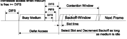
The basic 802.11 MAC protocol is the Distributed Coordination Function (DCF) that works as Listen-before-talk scheme, based on the Carrier Sense Multiple Access (CSMA). Stations deliver MAC Service Data Units (MSDUs) of arbitrary lengths (up to 2304 bytes), after detecting that there is no other transmission in progress on the wireless medium. However, if two stations detect the channel as free at the same time, a collision occurs. The 802.11 defines a Collision Avoidance (CA) mechanism to reduce the probability of such collisions. As part of CA, before starting a transmission a station performs a backoff procedure. The station computes a random time interval named Backoff time, uniformly distributed between zero and the current Contention Window size (CW), Backoff_time = rand[0; CW], where CWmin <CW < CWmax and Slot_time depends on the PHY layer type. The backoff timer is decreased only when the medium is idle, whereas it is frozen when another station is transmitting. Each time the medium becomes idle, the station waits for a DIFS and then continuously decrements the backoff timer. As soon as the backoff timer expires, the station is authorized to access the medium. It has to keep sensing the channel for an additional random time after detecting the channel as being idle for a minimum duration called DCF Interframe Space (DIFS), which is 34 us for 802.11a. Only if the channel remains idle for this additional random time period, the station is allowed to initiate the transmission. The duration of this random time determined as a multiple of a slot time (9 us in 802.11a). Each station maintains a so-called Contention Window (CW), which is used to determine the number of slot times a station has to wait before transmission.
For each successful reception of a frame, the receiving station immediately acknowledges the frame reception by sending an acknowledgement frame (ACK).
the contention window is doubled until a predefined maximum value CWmax is reached. To improve the channel utilization, after each successful transmission, the contention window is reset to a fixed minimum value CWmin. Stations deferred from channel access during the channel busy period do not select a new random backoff time, but continue to count down the time of the deferred backoff in progress after sensing a channel as being idle again. In this manner, stations, that deferred from channel access because their random backoff time was larger than the backoff time of other stations, are given a higher priority when they resume the transmission attempt. After each successful transmission, another random backoff is performed by the transmission-completing station, even if there is no other pending MSDU to be delivered. This is called “post-backoff”, as this backoff is done after, not before, a transmission.
[image:2.612.316.542.199.312.2]The Network Allocation Vector (NAV) is used for MAC virtual carrier sensing, by updating the local NAV with the value of other stations' transmission duration. By using NAV, a station can know when the current transmission ends and channel is idle.
Fig 1: Basic Access Method (DCF)
B. PCF of IEEE 802.11 MAC
Time-bounded data such as voice, audio or video is supported in the 802.11 MAC specifications through the PCF optional function. In PCF mode, a single AP controls the stations to access the media. PCF uses a centralized polling scheme, normally round robin, which requires the AP as a point coordinator (PC). If a BSS is set up with PCF-enabled, the channel access time is divided into periodic intervals named beacon intervals, with a Contention-Free Period (CFP) followed by a Contention Period (CP). During the PCF mode, the Point Coordinator (PC) maintains a list of registered stations and polls each station one by one according to the list. No station is allowed to transmit unless it is polled, and stations receive data from the AP only when they are polled. Since PCF gives every station a turn to transmit in a predetermined order, a maximum latency is bounded. Since every STA is permitted a maximum length of frame to transmit, the maximum CFP duration for all the STAs can be known and decided by the PC, which is called CFP_max_duration.
The PC first senses the channel for a PIFS interval (PCF InterFrame Space) and then starts a CFP by broadcasting a beacon signal. The time used by the PC to generate beacon frames is called target beacon transmission time (TBTT). In the beacon, PC denotes the next TBTT and broadcasts it to all other STAs in the BSS. Note that PIFS is shorter than DIFS, which allows the AP to gain the control from DCF mode and no DCF stations are able to interrupt the operation of PCF mode.
All stations add CFPmaxduration (the maximum possible duration of the Contention Free Period) to their own NAVs, which prevents themselves taking control of medium during
[image:2.612.76.300.301.370.2]CFP. Later, active users with time-bounded packet streams are periodically polled by the PC. The PC can terminate the CFP at any time by transmitting a CF-end packet, which occurs frequently when the network is lightly loaded. When a terminal's turn in the polling list comes, the PC sends a buffered data packet to it, piggybacked with a CF-Poll or an ACK for the previous transmission. The receiver sends back an ACK or any buffered data piggybacked with an ACK after a SIFS interval. Almost all packet transmissions are separated by SIFS except for one scenario: when the polled station does not respond the AP's poll within the SIFS period, the AP transmits its next packet after a PIFS from the end of the AP's last transmission.
Fig 2: PCF and DCF cycles
III.MODELLING AND SIMULATION
A. Description of the Simulation Model
Discrete-event simulation of the MAC portion of the IEEE 802.11 protocol was used. Simulated model is a campus network that uses wireline distribution backbone. The campus is compact, with 3 buildings including administrative, academic and residential. Every building is wired to the campus backbone network, connecting it to the main building’s server farm. Access point (AP) has a range of about 130–350feet. Although there was no specific effort to cover outdoor spaces, the campus is compact and the interior APs tend to cover most outdoor spaces.
All APs share the same network name (SSID), allowing wireless clients to roam seamlessly from one AP to another. On the other hand, a building’s APs are connected through a switch to the building’s existing subnet.
Fig. 3 Campus Network layout
IV.PERFORMANCE ANALYSIS
[image:2.612.325.531.516.651.2]A. Number of nodes per AP
Checking the maximum number of nodes an AP can support, with same traffic load, against transmission speed and MAC protocol is the aim of this experiment. Each Academic building contains of 3 floors, each floor is equipped with five access points.
From Table I, throughput measured against number of nodes and MAC protocol is quite the same, as medium is not saturated at the current load level, all generated data traffic reaches its destination sooner or late. Medium access delay for high speed WLAN, 54 Mbps, is very low compared to 11Mbps, which can be very useful in case of delay sensitive application.
TABLEI
THROUGHPUT AND MEDIA ACCESS DELAY AGAINST IEEE PROTOCOL AND NUMBER OF STATIONS/ACCESS POINT
MAC/ Mbps #of St/AP Throughput bps Media Access Delay msec Delay msec
11b/11 10
20 30 40 14,625,745 27,681,577 40,535,239 52,154,655 5.55 6.55 7.67 8.78 6.46 7.48 8.63 9.76
11g/11 10
20 30 40 14,683,336 27,604,277 40,551,931 51,885,745 3.51 4.09 4.45 5.63 4.37 4.97 5.35 6.57
11g/54 10
20 30 40 14,667,421 27,618,716 41,066,665 51,693,620 0.41 0.633 1.27 1.4 0.59 0.72 1.5 1.63
11a/54 10
20 30 40 14,732,044 27,618,716 40,929,625 51,852,645 0.41 0.51 1.13 1.26 0.59 0.682 1.33 1.46
B. Tuning of WLAN parameters
Setting WLAN parameters is crucial to the network performance, it can affect network performance badly if set without investigation on the network load and type of data flows, especially for delay sensitive applications.
Fragmentation Threshold is an important parameter that affects WLAN performance. It is used to improve the WLAN performance when the media error rate is high.
Also PCF can be used to tune node WLAN MAC parameters when PCF functionality is enabled.
Below we will study the effect of enabling PCF on a station over the Media access delay and retransmission attempts compared to a DCF node. A sample network was simulated to show the effect of PCF over MAC parameters, network consists of ten WLAN Stations, seven is PCF enabled Stations, All stations generate traffic with same load.
[image:3.612.321.529.43.347.2]As seen in Fig. 4 to 5, when we compare DCF and PCF stations, throughput measured for both is quite same. As a benefit of being allowed to use also the contention free periods, PCF stations transfer its data with much less number of retransmission compared to DCF stations.
Fig. 4 Throughput for DCF and PCF station.
[image:3.612.64.309.228.435.2]Fig. 5 Number of retransmission for a PCF enabled station.
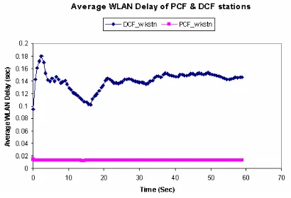
Fig. 6 compares average WLAN delays measured at both PCF and DCF stations. Since they need less number of retransmission, the delays experienced by the packets received by PCF stations are significantly lower than delays of DCF’s packets. In addition to that, PCF stations also observe less variation in delay values of the received packets, which can be a key quality requirement for some application types.
Fig. 6 Average WLAN Delay for a PCF against DCF enabled stations. Next we will study the effect of number of PCF enabled station on campus network performance.
Performance of seven PCF stations per AP
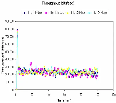
[image:3.612.325.530.469.609.2]Fig. 7 Throughput *5 of campus network with 7 PCF station/AP
[image:4.612.325.527.55.213.2]From Fig. 8 to 9, enabling PCF on the 54 Mbps network will significantly increase performance of those stations achieving almost zero retransmission attempts, when compared to DCF stations average retransmission attempts is much higher. For 11 Mbps enabling PCF has almost no effect on those stations.
[image:4.612.327.528.232.395.2]Fig. 8 Average Retransmission attempts for DCF enabled stations.
Fig. 9 Average Retransmission attempts for PCF enabled stations.
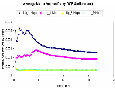
From Fig. 10 to 11, media access delay for PCF stations has significantly lower value that that DCF enabled station for 11 Mbps network.
[image:4.612.83.283.317.489.2]Fig. 10 Average media access delay for DCF enabled station.
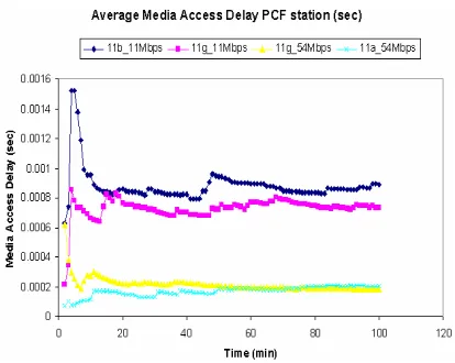
Fig. 11 Average media access delay for PCF enabled station.
Performance for five PCF station per AP
From Fig. 12, throughput of 11g-11Mbps has improved when PCF is enabled on five stations out of ten -almost close to the value when no PCF station is enabled-, a slight difference is due to the overhead of the control traffic due to PCF polling mechanism.
Fig. 12 Throughput *5 of campus network with 5 PCF station/AP
[image:4.612.324.530.500.683.2] [image:4.612.87.285.517.682.2]Fig. 13 Retransmission attempts for DCF enabled stations
[image:5.612.81.290.46.194.2]Retransmission attempts for PCF enabled station has improved to almost zero attempts improving those station performances’, as shown in Fig. 14. For delay sensitive application such functionality will effectively improve time-bounded application performance.
Fig. 14 Retransmission attempts for PCF enabled stations.
Media access delay for PCF station has dropped significantly, as shown in Fig. 16, For 11 Mbps media access delay of PCF stations is now compared to media access delay of 54 Mbps stations.
From above we conclude that we can improve performance [4]-[5] of the 11 Mbps to be compared to the 54 Mbps network on correctly setting the number of PCF nodes per access point
[image:5.612.84.286.290.438.2]Fig. 15 Average media access delay for DCF enabled station
Fig. 16 Average media access delay for PCF enabled station
C. PCF and introduced Load
To measure the effect of the introduced traffic load against PCF setting, we have introduced less traffic load on each station. Hence load per access point will be lower than the cases before. We also enabled PCF on seven stations per Access point.
As seen from Fig.17 throughput of the campus network for different IEEE protocols and transmission speeds, is almost equal, though we have set seven stations out of ten to be PCF enabled. In this scenario Overhead of the control traffic is not significant as in above scenarios.
Fig. 17 Throughput*5 of campus network with 7 PCF station/AP
From Fig. 18, retransmission attempts for DCF stations is much lower than pervious scenarios, this is due less introduced traffic load.
As shown in Fig. 19, retransmission attempts have fallen down to zero for all transmission speeds, though we have seven PCF enabled station per access point.
[image:5.612.326.528.361.540.2] [image:5.612.84.285.559.715.2]Fig. 18 Retransmission attempts for DCF enabled stations
Fig. 19 Retransmission attempts for PCF enabled stations
[image:6.612.83.285.196.423.2]From below Fig. 20 to 21, Media access delay for PCF station is lower than DCF stations.
Fig. 20 Average media access delay for DCF enabled station
Fig. 21 Average media access delay for PCF enabled station
V. CONCLUSION
The IEEE 802.11 WLAN supports multiple PHY rates; in this paper we investigated the WLAN performance with various transmission speeds. Estimating the traffic load introduced by the WLAN network Users’ will help the network administrator to determine number of AP needed in each floor accordingly for the whole campus network.
Also the effect of enabling PCF on a campus network stations was investigated. Enabling PCF functionality should be done after good study of the whole network and the total estimated load on every access point, as it may affect overall performance badly. Estimating traffic load over an AP will help to determine number of PCF stations per access point without affecting the overall performance of the network. Correctly setting number of PCF station will tune the performance of those nodes as well as overall network performance.
At future work, effect of coexistence of multiple IEEE protocol on the campus network performance can be studied. Low speed WLAN, 11 Mbps, stations moving to high speed WLAN, 54Mbps, will affect badly the global throughput of the network, increasing data dropped during the period this station is attached to 54 Mbps access point and accordingly decreasing throughput during that period due to protection mechanism followed by the 54 Mbps stations, they have to transmit with the lower speed accordingly the over all network will operate on lower transmission speed.
REFERENCES
[1] IEEE Std. 802.11-1999, Part 11: Wireless LAN Medium Access Control
(MAC) and Physical Layer (PHY) specifications, Reference number ISO/IEC 8802-11:1999(E), IEEE Std. 802.11, 1999 edition, 1999. [2] IEEE Std. 802.11b, Supplement to Part 11: Wireless LAN Medium Access Control (MAC) and Physical Layer (PHY) specifications: Higher-speed Physical Layer Extension in the 2.4 GHz Band, IEEE Std. 802.11b-1999, 1999.
[3] OPNET Technologies, Inc., “Wireless LAN model description,” http://www.opnet.com/products/library/WLAN_M odel_Guide1.pdf.
[4] F. Cali, M. Conti, and E. Gregori, “Dynamic tuning of the IEEE 802.11 protocol to achieve a theoretical throughput limit, ”IEEE/ACM
Transactions on Networking, vol. 8, no. 6, Dec.2000, pp. 785-799.
[image:6.612.81.286.489.691.2]