Max Strauß,1 Alexander Carmele,2 Julian Schleibner,2 Marcel Hohn,1 Christian Schneider,3 Sven H¨ofling,3, 4 Janik Wolters,1, 5 and Stephan Reitzenstein1
1Insitut f¨ur Festk¨orperphysik, Technische Universit¨at Berlin, D-10263 Berlin, Germany
2Institut f¨ur Theoretische Physik, Technische Universit¨at Berlin, D-10263 Berlin, Germany
3Technische Physik, Physikalisches Institut,Wilhelm Conrad R¨ontgen Center for Complex Material Systems,
Universit¨at W¨urzburg, D-97074 W¨urzburg, Germany 4
SUPA, School of Physics and Astronomy, University of St. Andrews, St. Andrews KY16 9SS, United Kingdom 5
Present address: Department of Physics, University of Basel, Klingelbergstrasse 82, CH-4056 Basel, Switzerland
(Dated: February 20, 2019)
S-I. SAMPLE TECHNOLOGY
The experiment is based on self-assembled semiconductor InGaAs quantum dots (QDs) grown by molecular beam epitaxy (MBE). The QDs with an Indium content of 60 % are embedded in a GaAs host matrix and were grown by the Stranski-Krastanov growth mode at a temperature of 520◦C. Here, the Indium flush technique [1] was applied to blue-shift the emission by precisely controlling the height of the QDs. The QDs have a density of about 109cm−2and the height and lateral dimensions of the modulation doped QDs are about 2 nm and 20 nm, respectively. The ensemble emission is centered at approximately 927 nm and the typical biexciton-exciton binding energy is in the range of 1-3 meV. To enhance the photon extraction efficiency the QD layer is embedded the center of the one-λthick GaAs cavity of a planar low-Q distributed Bragg reflector (DBR) cavity consisting of 24 lower and 5 upper mirror pairs. In addition to the improved directionality obtained by embedding the QDs into the planar microcavity, additional increase of their photon extraction efficiency up to 42% is achieved for QDs which self-align to Gaussian shaped nanohill defects that naturally form during the epitaxial growth [2]. A typical micro-photoluminescence (µPL) spectrum of the sample recorded at 5 K and an excitation power of 140 nW is presented in Fig. S1. It shows a strong single-QD line at approximately 924.9 nm which was used for investigating the Wigner time delay under pulsed resonant excitation in the main text.
9 1 5 9 2 0 9 2 5 9 3 0 0 . 0
0 . 5 1 . 0
In
te
n
s
it
y
(
a
rb
.
u
n
it
s
)
W a v e l e n g t h ( n m )
1 . 3 5 2 1 . 3 4 4 1 . 3 3 6
[image:1.612.164.432.478.676.2]E n e r g y ( e V )
PBS λ/4
λ/2
LP
PBS
70:30
OD
Power-meter
- Spectrometer
- SPCMs
- HBT
- FPI
Laser
Cryostat + sample
[image:2.612.135.486.55.274.2]EOM
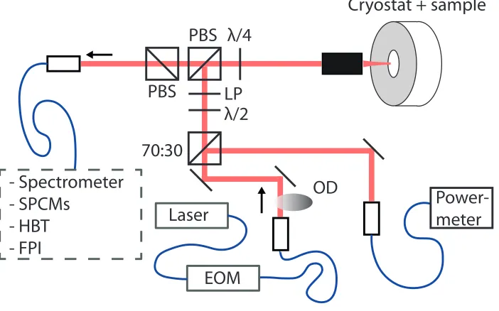
FIG. S2. Sketch of the experimental setup. Abbreviations: EOM - electrooptical modulator, FPI - Fabry-Perot interferometer, HBT - Hanbury Brown and Twiss interferometer, LP - linear polariser, λ/2 - half wave plate, λ/4 - quarter wave plate, OD - optical density filter, PBS - polarising beam splitter, SPCM - single-photon counting module.
S-II. EXPERIMENTAL SETUP
The QD is excited by a tunable resonant CW diode laser and a weak non-resonant diode laser (λ= 785 nm) (not shown in Fig. S2). The fiber coupled resonant and non-resonant laser are superimposed using a fiber beam splitter. The amplitude of the resonant laser can be temporally modulated using a fiber based electro-optical modulator (EOM) with an extinction above 1:1000. The EOM is controlled by a customized programmable pulse generator allowing for arbitrary pulse shapes with a maximum achievable length of ∆t = 1.05 ns (FWHM). The light is then coupled to free space as a collimated beam. To ensure a high degree of linear polarization the laser beam passes a half-wave plate (λ/2) and a linear polarizer (LP) prior to being reflected by a polarizing beam splitter (PBS) towards the sample. The beam is focused onto the sample using a microscope objective (NA=0.65). The sample itself is mounted inside a helium-flow cryostat and cooled to a temperature of 5 K. The fluorescence is collected by the same microscope objective. The reflected laser and fluorescence are separated by polarization filtering using two PBSs that transmit light orthogonal to the excitation and by focusing the collected light onto the facet of a single-mode fiber prior to photodetection. The luminescence is detected by a single-photon counting module and photon counts are histogrammed using a time-correlated single-photon counting (TCSPC) electronics with an overall timing resolution of ∆τFWHM= 390 ps.
S-III. RESONANCE FLUORESCENCE EMISSION SPECTRA OF A QUANTUM DOT TWO-LEVEL
SYSTEM
0
2
4
- 4 0
- 2 0
0
2 0
4 0
0 . 0
0 . 5
P = 1 3 0 P
s a tP = 0 . 1 4 P
s a tIn
te
n
s
it
y
(
a
rb
.
u
n
it
s
)
[image:3.612.163.451.59.263.2]E m i s s i o n f r e q u e n c y ( 2
π
* G H z )
FIG. S3. Resonance fluorescence emission spectra below (bottom) and above saturation (top). At high excitation powers the emergence of sidebands is evidence of the resonant interaction between coherent light field and TLS. The red lines are Lorentzian fits to the data.
contribution.
S-IV. THEORETICAL MODELLING VIA NON-MARKOVIAN LINDBLAD FORMALISM
It is known that lattice vibrations in semiconductor nanostructures give rise to new effects not known in typical atomic quantum optics and which are not included in Markovian treatments of the semiconductor environment such as mediated off-resonant cavity feeding [5, 6], formation of assisted Mollow triplets [7, 8], phonon-assisted Rabi oscillations [9, 10] and exciting reservoir correlation length in Hong-Ou-Mandel type of experiments [11, 12]. These features stem from the non-Ohmian spectral density of the semiconductor lattice vibrations. Lindblad-related master equation treatments usually do not include these features and therefore overestimate the impact of dephasing. Here, we model the dynamics via a Born-factorization, and cluster-expansion approach which is valid up to a temperature of 50 K and in the weak-driving limit. Beyond this limit, an extended Lindblad-approach can be employed [13] but our system under study at cryogenic temperatures of about 5 K is well-described in the factorization approach. The Hamiltonian of the system in the Born-Oppenheimer limit reads:
H/~=(ωg−ωL)a†cac+ Ω(t) a
†
vac+a
†
cav
+X
q
ωqb†qbq+ X
q
gvcqbq+gvcq∗b†q
a†cac (S1)
for a rotating frame in the laser frequency and detuning ∆ =ωg−ωL. The coupling to acoustic phonons is incorporated, and the linear dispersion reads: ωq =cs|q|. The coupling element is the deformation potential. The laser excitation reads
Ω(t) =ΩL
r π
(2τ2)exp
−(t−t0) 2
2τ2
(S2)
with the amplitude ΩL. The semiconductor Bloch equation are solved in the Heisenberg picture. The one-electron assumption is assumeda†vav= 1−
∂t
a†cac=−2Γa†cac+ 2ImΩ(t)a†vac (S3)
∂t
a†vac=−(Γ +i∆)a†vac−iΩ(t) 2a†cac−1−iX q
gvcq bqa†vac+gvcq∗b†qa†vac (S4)
∂tbqa
†
vac
=−(Γ +i∆ +iωq)bqa
†
vac
−iΩ(t) 2
bqa†cac −
bq
−igqvc∗
b†qbq a†vac
(S5)
∂t
b†qa†vac=−(Γ +i∆−iωq)
b†qa†vac−iΩ(t)2bqa†cac∗−
bq∗−igqvcbqb†q a†vac (S6)
∂t
bqa†cac
=−(2Γ +iωq)
bqa†cac
−iΩ(t)bqa†vac
−
b†qa†vac ∗
+igqvc∗
b†qbq a†cac
(S7)
∂t
bq=−iωq
bq−igqvc∗a†cac. (S8)
In the low temperature limit, the second-order factorization is still valid, and allows via the bath assumption to include stimulated phonon emission and absorption. The phonon occupation number are given via the Bose-Einstein distribution and depends on the temperature via:
b†qbq
= [exp(~ωq/(kBT))−1]
−1
(S9)
The coupling element of the QD to the phonon continuum is determined via the deformation potential. This potential depends on the confinement energies of electrons and holes of the QDs, and on the semiconductor background material. We use the standard parameter of deformation coupling values of an approximate spherical QD. Phonon coupling element|gq
vc|=|gvvq −gccq|, where
gqi = s
~q
2ρcsV Die
− q2~
4miωi. (S10)
Used parameters: sound velocity of GaAscs= 0.00511nm/fs, deformation potentialsDv =−5.38eV, Dc =−11.68eV, effective masses: mc = 0.063, mv = 0.45, confinement energies ~ωc = 0.040eV, ~ωv = 0.02eV and mass density of GaAsρ= 5370kg/m3 [6, 14, 15].
In the calculations, we fixed the radiative decay time to the experiment Γ = 600ps−1, and choose a time-scale, so we reproduce the maximum of the Wigner delay on resonance at ∆ = 0, for a pulse width ofτ = (10Γ)−1and a fixed pure dephasing for a given pulse area fixed at ΩL= 0.4 for the detuning dependent parameter plot. This pulse area is changed but everything else is kept fixed for the power parameter plot on resonance.
S-V. ON THE REPRODUCIBILITY OF THE WIGNER TIME DELAY OF A RESONANTLY DRIVEN
QUANTUM DOT
-2 -1 0 1 2 3 4 0.0
0.2 0.4 0.6 0.8 1.0
0 100 200 300 400 500
-3 -2 -1 0 1 2 3
0.0 0.2 0.4 0.6 0.8 1.0
Fluorescence
Time (ns) Laser
(a)
(c) (b)
Detuning (GHz)
-10 -5 0 5 10
Detuning (meV)
Norm. int. (arb. units)
Delay (ps)
[image:5.612.166.477.66.288.2]Normalized intensity (arb. units)
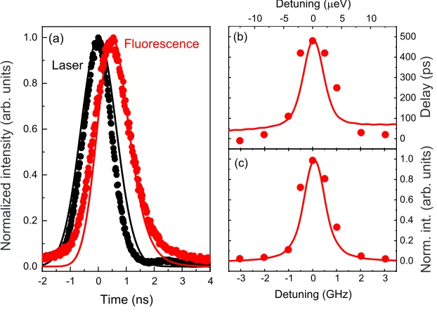
FIG. S4. Wigner time delay of a second QD. The QD was studied under the same experimental parameters than the one in the main text. It a Wigner time delay of about 500 ps under resonant excitation (see panel (a)) and the characteristic decrease of the time delay for increasing detuning between the TLS and the excitation laser (see panel (b). Panel (c) shows the intensity of the resonantly scattered light as a function of laser detuning. The experimental data is well described by theoretical curves (red lines) taking our non-Markovian model into account.
[1] J. M. Garcia, T. Mankad, P. O. Holtz, P. J. Wellman, and P. M. Petroff. Electronic states tuning of InAs self-assembled quantum dots. Appl. Phys. Lett., 72:3172, 1998.
[2] S. Maier, P. Gold, A. Forchel, N. Gregersen, J. Mørk, S. H¨ofling, C. Schneider, and M. Kamp. Bright single photon source based on self-aligned quantum dot–cavity systems. Opt. Express, 22:8136, 2014.
[3] C. Cohen-Tannoudji, J. Dupont-Roc, and G. Grynberg. Atom-Photon Interactions: Basic Processes and Applications. Wiley-VCH, 2004
[4] H. S. Nguyen, G. Sallen, C. Voisin, P. Roussignol, C. Diederichs, and G. Cassabois. Ultra-coherent single photon source.
Appl. Phys. Lett., 99:261904, 2011.
[5] S. Hughes, P. Yao, F. Milde, A. Knorr, D. Dalacu, K. Mnaymneh, V. Sazonova, P. J. Poole, G. C. Aers, J. Lapointe, R. Cheriton, and R. L. Williams. Influence of electron-acoustic phonon scattering on off-resonant cavity feeding within a strongly coupled quantum-dot cavity system. Phys. Rev. B, 83:165313, 2011.
[6] U. Hohenester, A. Laucht, M. Kaniber, N. Hauke, A. Neumann, A. Mohtashami, M. Seliger, M. Bichler, and J. J. Finley. Phonon-assisted transitions from quantum dot excitons to cavity photons. Phys. Rev. B, 80:201311, 2009.
[7] S. M. Ulrich, S. Ates, S. Reitzenstein, A. L¨offler, A. Forchel, and P. Michler. Dephasing of triplet-sideband optical emission of a resonantly driven InAs/GaAs quantum dot inside a microcavity. Phys. Rev. Lett., 106:247402, 2011.
[8] J. Kabuss, A. Carmele, M. Richter, and A. Knorr. Microscopic equation-of-motion approach to the multiphonon assisted quantum emission of a semiconductor quantum dot. Phys. Rev. B, 84:125324, 2011.
[9] A. Vagov, M. D. Croitoru, M. Gl¨assl, V. M. Axt, and T. Kuhn. Real-time path integrals for quantum dots: Quantum dissipative dynamics with superohmic environment coupling. Phys. Rev. B, 83:094303, 2011.
[10] J. F¨orstner, C. Weber, J. Danckwerts, and A. Knorr. Phonon-assisted damping of Rabi oscillations in semiconductor quantum dots. Phys. Rev. Lett., 91:127401, 2003.
[11] A. Thoma et al. Exploring dephasing of a solid-state quantum emitter via time-and temperature-dependent Hong-Ou-Mandel experiments. Phys. Rev. Lett., 116:033601, 2016.
[12] Hui Wang et al. Near-Transform-Limited Single Photons from an Efficient Solid-State Quantum Emitter.Phys. Rev. Lett., 116:213601, 2016.
[13] C. Roy and S. Hughes Polaron master equation theory of the quantum-dot Mollow triplet in a semiconductor cavity-QED system. Phys. Rev. B, 85:115309, 2016.