Electric
Linear
Actuators
and Controls
Warner Linear...
Customer Focused, Quality Driven
Products designed and manufactured for reliable, long-lasting performance
Quality Processes
Warner Linear is dedicated to designing and manufacturing “Best-in-class” electromechanical actuators and controls. We subscribe to a standard of quality derived from the Altra Business System (ABS), a series of progressivemanufacturing methods designed to continuously improve production within our flexible work cell environment. Our quality starts in product design. It is demonstrated in the attention given to design details and the refinement of prototypes. It is apparent in our fast response to requests for quotes, and our strict adherence to deadlines in every stage of the work flow.
Custom Solutions
We recognize how critical our actuators are to the overall performance of yourequipment. Working closely with your engineering and development staff, we strive for an early understanding of how you want your linear actuator to perform. Building a direct communication line from our engineer to your engineer provides a number of significant benefits.
• A teaming of creative resources. • Joint understanding of our actuator
capabilities and how they can be tailored to your application.
• An understanding of the lowest cost solution to meet your actuator requirements.
• Providing a complete solution that includes controls as required.
Service to our
Customers
Our team takes pride in serving our customers with excellence and
enthusiasm and demonstrates this in all aspects of our business relationships. Our knowledgeable staff is involved on a daily basis in customer communications, team based problem solving, and continuous improvement. We are sensitive to satisfying specific customer requirements and expectations.
Design and Testing
Our engineers and design specialists work closely with our customers to define both lab and field testing requirements. Our solid model design capabilities, computer assisted testing, and manufacturing floor pre-shipment cycle test, all provide assurance that your Warner Linear actuators will meet or exceed your expectations. Our linear actuator testing capabilities include dual load life cycling stands, low and high pressure wash down test tanks, lift test stands and thermal shock submersion. Our test service providers add material analysis, noise and vibration evaluation capabilities.
State-of-the-Art Facilities
Our division headquarter’s facilityis a full function design and manufacturing centre located in Belvidere, Illinois. The facility is dedicated to the engineering, testing and assembly of Warner Linear actuators. Selective global sourcing of high quality
components from low cost countries provides the ultimate in actuator value.
Contents
Applications/ Performance Features 4-5 M-Track Design Features 6 M-Track Configurator 7 M-Track 1 8-9 A-Track Design Features 10 A-Track Configurator 11 A-Track 2 12-13 A-Track 5 14-15 A-Track 5 16-17 A-Track 10 18-19 B-Track Design Features 20 B-Track Configurator 21 B-Track K2VL 22-23 B-Track K2 24-25 B-Track K2X 26-27 B-Track K2PL/K2XPL 28-29 B-Track K2JS/K2XJS 30-31 B-Track K2RA 32-33 Custom Actuators 34 Mounting Information 35 Performance Features 36 Controls –Simple & Basic 37-38 Controls – Advanced 39 Controls – BTc P1-DC 40-41 Controls – BTc PQS-DC 42-43 Controls – BTc P2-DC 44-45 Glossary 46-47 Application Data Form 48
Warner Linear offers a full line of standard electric actuators, each specifically designed to meet the needs of light-duty, general-duty, or rugged-duty applications. All are engineered for maintenance-free, long-life service, providing maximum value for our customers.
Linear actuators to meet your
specific requirements
M-Track 1
Compact, completely self-contained and sealed to allow for use in small spaces without sacrificing power or capability.
Drive Type: Acme Screw
Load Capacity & Speed: 120 N @ 45 mm/s 240 N @ 24 mm/s 500 N @ 13 mm/s 750 N @ 06 mm/s Stroke Length (mm): 50, 100, 150, 250, 300 Input Voltage (VDC): 12, 24 Typical Applications: Throttle Control Air Vent Opening Remote Window Operation Remote Mirror Positioning Gate Opening Shutter Control Light Duty
QUICK SELECTION GUIDE
A-Track 2
Efficient design offering low cost power capability. For use in applications where moisture or environmental contamination exist.
Drive Type: Acme Screw
Load Capacity & Speed: 1500 N @ 25 mm/s 2300 N @ 13 mm/s Stroke Length (mm): 100, 150, 200, 300, 450, 600 Input Voltage (VDC): 12, 24 Typical Applications: Drum Lifts
Access Panel Lifts Walk Behind Sweeper/ Polishers
Tractor Hood Lifts Spout Positioning
General Duty
Pages 12-13
A-Track 5
Efficient design offering moderate power capability. For indoor use or where AC power is available.
Drive Type:
Acme or Ball Screw Load Capacity & Speed: 1500 N @ 25 mm/s 2300 N @ 46 mm/s 4500 N @ 25 mm/s 6000 N @ 12 mm/s Stroke Length (mm): 100, 150, 200, 300, 450, 600
Input Voltage (VAC): 115, 230
Typical Applications: Work Table Positioning Conveyor Positioning Remote Louver Control Door Opening Vent Control Scissor Lift Tables
Pages 14-17
A-Track 10
Completely self-contained for more demanding outdoor applications requiring moderate load and duty cycle capability.
Drive Type:
Ball Screw
Load Capacity & Speed:
2300 N @ 45 mm/s 3500 N @ 22 mm/s 4500 N @ 13 mm/s Stroke Length (mm): 100, 150, 200, 300, 450, 600 Input Voltage (VDC): 12, 24 Typical Applications: Boat Engine Covers Round Baler Covers Engine Hoods Scooter Lifts
Pages 18-19
Rugged Duty
B-Track K2VL
Intended for severe service requirements and loads up to 3500 N. Lowest priced model in the B-Track family.
Drive Type:
Hybrid Acme
Load Capacity & Speed:
900 N @ 50 mm/s 1500 N @ 25 mm/s 3400 N @ 12 mm/s Stroke Length (mm): 50-600 in 50 mm increments Input Voltage (VDC): 12, 24, 48, 90 Typical Applications:
Fertilizer Gate Control Mower Decks Gate Openers Scooter & Cycle Lifts Pull Behind Implement Lifts
Pages 22-23
B-Track K2
Uses a patented straight line load transfer offering high load capability in a small package size. Bronze or Delrin® nut options available for high impact load applications. Drive Type:
Hybrid Acme
Load Capacity & Speed:
1300 N @ 50 mm/s 2700 N @ 25 mm/s 5400 N @ 12 mm/s Stroke Length (mm): 50-900 in 50 mm increments Input Voltage (VDC): 12, 24, 48, 90 Typical Applications:
Residential Mower Decks Gate & Valve Operation Snow Blowers Spouts & Chutes Engine Lifts Tables Wagon Lifts Combine Concaves Pages 24-25 B-Track K2X Completely sealed, designed for tough, high load applications. Able to perform in harsh environments providing years of trouble-free service.
Drive Type:
Ball Screw & Ball Nut
Load Capacity & Speed:
2600 N @ 50 mm/s 5400 N @ 25 mm/s 9800 N @ 12 mm/s Stroke Length (mm): 50-900 in 50 mm increments Input Voltage (VDC): 12, 24, 48, 90 Typical Applications: Paving Outriggers Commercial Mower Decks Spray Booms
ATV Dump Box Lifts Boat Engine Lifts Hydraulic Cylinder Replacement Construction Equipment Hood Lifts Pages 26-27
Actuator Controls
Simple extend/retract switch boxes
• SBC-DC, SBC-AC
Basic controls and digital electronic options
• Adjustable stroke limits
• Fixed electronic stroke limits – ESL
• QS Quick Stop bi-directional current limit control
• Position feedback options – potentiometer or digital outputs
Microprocessor based controls (for special needs)
• Quick Switch and Twin Track control functions • Programming pendant
• Adjustable position and current limit options • Remote mounting capable
Golf Cart Height Adjust
Mower Blade Lift
Solar Panel Adjust
55 Gallon Drum Lift
Fire Engine Valve Adjust
Automated Dumpster
Scissor Lift Table
Round Baler Cover Lift
Walk Behind Floor Washer
Bulldozer Engine Cover
Air Foil Adjust
Construction Sign Positioning
Forage Harvester Spout Positioning
Combine Spout Positioning
Adjustable Height Work Table
Conveyor Lateral Guide Positioning
Street Sweeper Bristle Lift
RV/Bus Compartment Extension
Warner Linear
Actuators are
available for a wide
variety of
applications
Performance Features
Dependable Operation
Compact design
A Warner Linear actuator with a 50 mm stroke can provide up to 9000 N of force capacity in a compact package.
Maintenance-free
Units are lubricated for life during assembly. There are no adjustments or maintenance required for units after they have left the factory. Consistent performance is provided for the entire life of the actuator.
Equal capacity in both directions
Warner Linear actuators can push-and-pull or lift-and-lower loads ranging from 5 N to over 9000 N up to 600 mm with equal capacity in both directions of travel.
Efficient operation
Warner Linear actuators consist of an electric motor combined with a high efficiency gear train and lead screw. This direct conversion of electrical to mechanical energy results in effective, economic linear movement. Units are completely self contained and require minimal installation hardware or wiring.
Superb load holding power
Warner Linear actuators operate loads in both tension and compression equally well. They will hold a load stationary without power in either direction. Static load holding capability will always exceed the dynamic load moving capability.
Advantages
• No hydraulic pumps, hoses, valves, or leaks • Holds load when power is off
• Overload clutches prevent damage due to excess weight • Simple to install and use
• Easily adaptable for position control
Performance Features
Rugged and reliable
Warner Linear actuators incorporate high strength, high quality components and are designed to assure trouble-free service. Rugged spur gearing, industrial quality synthetic lubricants and high performance motors combine to provide maximum capability and value for the end user. Units are gasketed and sealed for operation in industrial and mobile outdoor applications. Thermal overload switches are included for motor protection; and high performance corrosion protection features are standard.
Energy efficient
Electric control provides clean, smooth linear motion without fluids, plumbing or other expensive components. Warner Linear actuators require power only when in motion. No power is required to hold loads stationary.
Lead screw drive systems
Warner Linear actuators use either acme, hybrid rolled, or highly efficient ball bearing screws. Models which use acme or hybrid rolled screws with bronze or plastic nuts will not backdrive when power is off. A bi-directional load holding brake is a standard feature on all ball bearing units and holds loads in position when power is off.
Overload protection
Motors incorporate thermal switches in their windings to shut the actuator motor off in case of overheating or high overcurrent. Reset is automatic after the motor has cooled. A standard overload clutch detents if the load is excessive or reaches end of stroke.
Note: Clutch is not incorporated in M-Track due to size constraints.
Versatile
With their compact size, Warner Linear actuators can be located in confined areas, and move loads from 0 to 9000 N. Their static load holding ability ensures that a load will remain in position when power is turned off. Gearing ratios create speeds that range from 12 to over 50 mm per second. Standard models are mounted using two parallel pins and require only simple wiring and switches. They are self-contained, lubricated for life, and designed for use where rugged and durable performance is required for almost any lift-and-lower or push-and-pull application.
Available customized features
• Direct drive manual override • Mounting and end fitting variations • DC Motor voltage variations • AC and DC motor options • Motor lead wire connectors
• Adjustable stroke limit switches – fixed and adjustable • Position feedback outputs – potentiometer and digital
Also available
• Basic switch box controls
• Integrated electronic position controls
Acme screw
M-Track - Features
Thermal overloads in windings protect the motor
Metal spur gears offer strength and durability
Integrated rear clevis for easy
pin-to-pin mounting Optional potentiometer assures accurate, consistent positioning feedback
Compact spur gear design allows compact space re-quirements
Integral end of stroke limit switches standard. No clutch required.
Lightweight aluminum extension rod
Wiper and O-ring provide double protection and
load support
Light Duty Actuators
Key Features
• Compact size
• Efficient design
• Easy to use and install
Standard models
M-Track - Configurator
How to select
Step 1 – Determine load and stroke length requirements Use the Quick Selection guide to identify the model that will provide the load capacity and stroke length needed for your application.
Step 2 – Identify motor type and voltage Select DC motor and motor voltage.
Step 3 – Confirm speed and current draw requirements Using the charts provided, confirm that unit speed and current draw is appropriate for the intended use.
Step 4 – Confirm the application duty cycle
At full load capacity, actuators have a 25% duty cycle. Duty cycle is the amount of ‘on-time’ compared to cooling time. A unit that runs for 15 seconds should be off for 45 seconds.
Important unit restrictions
Side loading and shock loads must be considered in actu-ator applications. Side loading and cantilevered mounting should be eliminated through proper machine design. Side loading will dramatically reduce unit life. While actuators can withstand limited shock loads, it is recommended that shock loading be avoided wherever possible. (See page 35)
Step 5 – Unit options
M-Track units include end-of-travel limit switches as a stan-dard feature. For positional feedback, a 10K ohm poten-tiometer can be factory installed. The changing potentiometer value provides unit movement feedback for units that are not visible to the machine operator.
01 = M-Track 1 D012 = 12 VDC D024 = 24 VDC D036 = 36 VDC 0025 = 120 N 0050 = 240 N 0100 = 500 N 0165 = 750 N A = Acme Screw Actuator Model No.
Motor Voltage Options
Load Capacity (N)
Screw Type
P = With Potentiometer N = No Potentiometer
L = Limit switches included
Potentiometer
Limit Switch Options
02 = 050 mm 04 = 100 mm 06 = 150 mm 08 = 200 mm 10 = 250 mm 12 = 300 mm Stroke Length (mm)
Model Voltage Load Screw Stroke Limit Potentiometer No. Capacity Type Length Switch
01 –
D012 –
0025 –
A
02 –
L
N
Not all stroke lengths are standard on all units. Consult unit page for details. Not all load ratings are
stan-dard for all units. Consult unit page for
M-Track 1
DC motor acme screw
750 N load rated
Features
• An Acme Screw drive delivers up to 750 N of force at a minimum extension rate of 6 mm per second • The aluminum zinc alloy housing resists
corrosion and provides protection from dirt, dust and humidity
• The M-Track 1 has a temperature operating range of –25ºC to +65º C • Standard stroke lengths of 50, 100,
150, 200, 250 and 300 mm are available
• Internal limit switches automatically shut off the unit at end of stroke • Optional potentiometer can provide
positional location feedback
Typical applications
• Light load and short distanceapplications such as: • Valve and vent adjustments • Light weight tilt or lift positioning • Vise and clamp operations M-Track 1 compact units are completely self-contained and sealed to
allow use in small spaces without sacrificing power or capability. The load and length capabilities provide solutions for a diverse range of intermittent duty applications.
Functionally, M-Track 1actuators are easily interchanged with compara-ble size hydraulic or pneumatic cylinders on intermittent duty applications. The actuator provides consistent, repeatable performance even for appli-cations with operating conditions including temperature extremes, high hu-midity, or significant dust.
Specifications
Load Capacity N 120 240 500 750
Speed at Full Load mm/s 45 24 13 06
Input Voltage VDC 12 or 24 VDC (36 VDC optional)
Static Load Capacity N 1300
Stroke Length mm 50, 100, 150, 200, 250, 300
Clevis Ends mm Ø 6,4
Duty Cycle % 25%
Operation Temperature Range °C -25ºC to +65ºC
Limit Switch - Fixed end of stroke limit switches standard
Potentiometer Ohm 10K, 10 turn pot optional
M-Track 1
Current vs load
Speed vs load
A: Retracted Length (with POT sensor) 192 243 294 345 N/A N/A
A: Retracted Length (without POT sensor) 158 209 260 311 362 413
B: Stroke Length 50 100 150 200 250 300
Dimensions (mm)
Performance curves
0 120 N 240 N 500 N 750 N 0 100 200 300 Load (N) 12 VD C (A) 24 VD C (A) 400 500 600 700 800 1 2 3 4 0 0.5 1.0 1.5 2.0 0 120 N 240 N 500 N 0 100 200 300 Load (N) Speed (mm/s) 400 500 600 700 800 15 30 45 60 750 N Ø20 40 20 18 75 Ø6,4 18 7 Lead Length 300 ±30 11 B ±2 A ±2 9,0 Ø6,4 Ø20 20,5 Ø3 8 135 18 Ø20 20 75 40 Lead Length 300 ±30 Ø6,4 18 7 86,4 Ø3 8 11 Ø6,4 17,7 9 B ±2 A ±2 20 A B 158 50 209 100 260 150 311 200 362 250 A B 192 50 243 100 294 150 345 200withPOT sensor
A-Track - Features
General Duty Actuators
Key Features
• Totally sealed
• Long life motor
• Easy to use and install
• Best value in its class
Standard models
A-Track 2, A-Track 5
A-Track 10
Sealed housing and motor protects wiring and internal components Clevis mount for
simple pin-to-pin mounting Load holding brake keeps loads station-ary with power off
Thermal overload in motors protects from excessive duty cycle Overload clutch protects gearing and motor from ex-cessive loads
Dual seal and O-rings provide protection from external contaminants
Stainless steel ex-tension tube pro-tects against corrosion Ball bearing screws provide high efficiency motion
Metal spur gears offer strength and durability
Sealed housing and motor protect wiring and internal components Clevis mount
for simple pin-to-pin mounting
Wipers and O-rings provide double protection from contaminants Stainless steel extension tube protects against corrosion Optional poten-tiometer provides positional feedback
Overload clutch protects gears and motor from excessive loads
Metal spur gears offer strength and durability
Thermal overload in motors protects from excessive duty cycle
End of travel limit switches provide automatic shut-off (Optional)
AC units use spring set anti-coast load holding brakes
Acme Screw Driven
Actuators...
designed for light to moderate duty applications.
Ball Screw
Driven Actuators...
designed for industrial and commercial applications requiring high load capacities.A-Track - Configurator
How to select
Step 1 – Determine load and stroke length requirements Use the Quick Selection guide to identify the model that will provide the load capacity and stroke length needed for your application.
Step 2 – Identify motor type and voltage Select AC or DC motor and motor voltage.
Step 3 – Confirm speed and current draw requirements Using the charts provided with each model family, confirm that unit speed and current draw is appropriate for the system design.
Step 4 – Confirm the application duty cycle
At full load capacity, actuators have a 25% duty cycle. Duty cycle is the amount of ‘on-time’ compared to cooling time. A unit that runs for 15 seconds should be off for 45 seconds.
Important unit restrictions
Side loading and shock loads must be considered in actu-ator applications. Side loading and cantilevered mounting should be eliminated through proper machine design. Side loading will dramatically reduce unit life. While actuators can withstand limited shock loads, it is recommended that shock loading be avoided wherever possible. (See page 35)
Step 5 – Unit options
A-Track units include end-of-travel limit switches as an optional feature. *For positional feedback, a 10K ohm potentiometer can be factory installed. The changing potentiometer value provides unit movement feedback for units that are not visible to the machine operator.
*Limit switches are only available in the maximum load configuration for each model. 02 = A-Track 2 05 = A-Track 5 10 = A-Track 10 D012 = 12 VDC D024 = 24 VDC A115 = 115 VAC A230 = 230 VAC 0330 = 1500 N 0500 = 2300 N 0750 = 3300 N 1000 = 4500 N 1300 = 6000 N A = Acme Screw B = Ball Screw Actuator Model No.
Motor Voltage
Load Capacity (N)
Screw Type
P = With Potentiometer N = No Potentiometer
L = Limit switches included N = No Limit switches
Potentiometer
Limit Switch Options
04 = 100 mm 06 = 150 mm 08 = 200 mm 12 = 300 mm 18 = 450 mm 24 = 600 mm Stroke Length (mm)
Model Voltage Load Screw Stroke Limit Potentiometer Base Fitting No. Capacity Type Length Switch Alignement
02 – D012 – 0330 –
A
04 –
L
N
R120
Not all stroke lengths are stan-dard on all units. Consult unit page for details. Not all load ratings are
standard for all units. Consult unit page for details. R30 = 30˚ Fitting R60 = 60˚ Fitting R90 = 90˚ Fitting R120 = 120˚ Fitting R150 = 150˚ Fitting Blank = Standard Base Fitting Alignment
30° 30° 30° 30° M2 R30 M3 R60 M4 R90 M5 R120 M6 R150 M1 30°
A-Track 2
DC motor acme screw
Up to 2300 N load rated
Up to 25 mm/s Speed
Features
• Seale and gasketed for mobile or outdoor applications • Overload clutch standard
• 100, 150, 200, 300, 450 and 600 mm stroke lengths
• 12 or 24 VDC motors • Acme screw drive
• Thermal overload included in double ball bearing motor
Typical applications
• Gate and valve positioning • Tailgate lifts• Mobile equipment spout positioning control
The A-Track 2incorporates an Acme screw drive system that provides a value priced unit for moderate duty applications. The A-Track 2includes lubrication for the life of the unit, combined with robust seal and O-ring design, creating a maintenance free design, even when used in applica-tions with high humidity or dust.
Specifications
Load Capacity N 1500 2300
Speed at Full Load mm/s 25 13
Input Voltage VDC 12 or 24 VDC
Static Load Capacity N 4500
Stroke Length mm 100, 150, 200, 300, 450 and 600
Clevis Ends mm Ø 13
Duty Cycle % 25%
Operation Temperature Range °C -25ºC to +65ºC
Limit Switch - Optional adjustable travel limit switches (20:1 only) (2300 N)
Potentiometer Ohm Optional feedback potentiometer
Restraining Torque Nm 11,2
A-Track 2
Current vs load
Speed vs load
A 338 389 438 540 772 924 B 102 153 203 305 457 610 Stroke 100 150 200 300 450 600
Dimensions (mm)
Performance curves
0 1500 N 2300 N 0 500 1000 1500 Load (N) 12 VD C (A) 24 VD C (A) 2000 2500 4 8 12 16 20 0 2 4 6 8 10 0 2300 N 1500 N 0 500 1000 1500 Load(N) Speed (mm/s) 2000 2500 10 20 30 40 50 15 0,5 76 Ø13 Ø26 38 14 24,5 67,6 15,5 18 11,5 Ø50,8 28,6 Ø63,5 Ø13 130 163,5 107 55,5 B ±2,5 A ±3,8With Limit Switches
A-Track 2 Acme Screw
A 262 313 364 465 696 848
B 102 153 203 305 457 610
Stroke 100 150 200 300 450 600
Without Limit Switches
A-Track 2 Acme Screw
A-Track 5
AC motor acme screw
Up to 2300 N load rated
Up to 25 mm/s Speed
Features
• Acme screw drive system
• 115 VAC (60hz) and 230 VAC (50hz) motors available
• 100, 150, 200, 300, 450 and 600 mm strokes
• Acme screw drive train • Overload clutch standard • Lubricated for life
• Capacitor included with motor
Typical applications
• Ergonomic lift tables • Conveyor diverters • Bin/tank cover lifts • Roof vents The A-Track 5 Acme screwactuator is a general purpose AC actuatorwith load capacities of 1500 and 2300 N for use in moderate duty interior applications. The unit includes a power off motor stopping brake for faster stops and extra load holding capability. The Model 5 allows for stroke lengths of 100 to 600 mm for in-plant or protected applications.
Specifications
Load Capacity N 1500 2300
Speed at Full Load mm/s 25 14
Input Voltage VAC 115 VAC (60 Hz) and 230 VAC (50 Hz)
Static Load Capacity N 4500
Stroke Length mm 100, 150, 200, 300, 450 and 600
Clevis Ends mm Ø 13
Duty Cycle % 25%
Operation Temperature Range °C -25ºC to +65ºC
Limit Switch - Optional adjustable travel limit switches (20:1 only) (2300 N)
Potentiometer Ohm Optional feedback potentiometer
Restraining Torque Nm 11,2
A-Track 5
Current vs load
Speed vs load
A 456 506 556 658 810 962 B 102 153 203 305 457 610 Stroke 100 150 200 300 450 600
Dimensions (mm)
Performance curves
0 0 450 900 1350 Load(N) 115 V A C (A) 23 0 V A C (A) 1800 2250 0.6 1.2 1.8 2.4 3.0 0 0.3 0.6 0.9 1.2 1.5 1500 N 2300 N 0 0 450 900 1350 Load(N) Speed ( mm/s) 1800 2250 7,5 15 22,5 30 37,5 1500 N 2300 N 15 6 76 24,5 14 38 Ø26 Ø13 Both Ends 67,6 15,5 Ø50,8 30 11,5 9 55,4 271 600 ± 30 Ø8 7 Ø28,6 B ±2,5 A ±2,5With Limit Switches
A-Track 5 Acme Screw
A 380 431 481 583 735 887
B 102 153 203 305 457 610
Stroke 100 150 200 300 450 600
Without Limit Switches
A-Track 5 Acme Screw
A-Track 5
AC motor ball screw
Up to 6000 N load rated
Up to 48 mm/s Speed
Features
• Ball bearing screw drive system • Anti-coast load holding brake
• 100–600 mm stroke length capability • Load limiting clutch standard
• Thermal overload protection in the motor
• Capacitor included in motor
Typical applications
• Ergonomic lift tables • Conveyor diverters • Bin or tank cover lifts • Die transfer carts The A-Track 5 Ball Screwis a ball screw drive linear actuator forindus-trial and commercial applications. The unit provides load capacity up to 6000 N with either 115 or 230 VAC motors. This unit includes a power off load holding brake which stops the motor from turning when power is off. The Model 5 allows for stroke lengths of 100 to 600 mm for in-plant or protected applications.
Specifications
Load Capacity N 2300 4500 6000
Speed at Full Load mm/s 48 25 12
Input Voltage VAC 115 VAC (60 Hz) / 230 VAC (50 Hz)
Static Load Capacity N 13500
Stroke Length mm 100, 150, 200, 300, 450 and 600 mm
Clevis Ends mm Ø 13
Duty Cycle % 25%
Operation Temperature Range °C -25ºC to +65ºC
Limit Switch - Optional adjustable travel limit switch (20:1 only) (6000 N)
Potentiometer Ohm Optional
Restraining Torque Nm 11,2
A-Track 5
Current vs load
Speed vs load
A 456 506 556 658 810 962 B 102 153 203 305 457 610 Stroke 100 150 200 300 450 600
Dimensions (mm)
Performance curves
0 6000 N 4500 N 2300 N 0 1125 2250 3375 Load(N) 115 V A C (A) 23 0 V A C (A) 4500 5625 6750 0.6 1.2 1.8 2.4 3.0 0 0.3 0.6 0.9 1.2 1.5 0 6000 N 0 1125 2250 3175 Load(N) Speed (mm/s) 4500 5625 6750 13 26 39 52 65 2300 N 4500 N 76 15 6 Ø13 Both Ends 38 Ø26 Ø50,8 30 14 24,5 70 15,5 9 55,4 271 600 ± 30 Ø8 7 Ø28,6 11,5 B ±2,5 A ±3,8With Limit Switches
A-Track 5 Ball screw
A 380 431 481 583 735 887
B 102 153 203 305 457 610
Stroke 100 150 200 300 450 600
Without Limit Switches
A-Track 5 Ball screw
A-Track 10
DC motor ball screw
Up to 4500 N load rated
Up to 45 mm/s Speed
Features
• Efficient ball screw drive system • Load holding brake standard • Over load clutch standard • 100 to 600 mm stroke lengths • Thermal overload incorporated into
the motor
Typical applications
• Heavy duty platform lifts• Deck and implement lifts for tractors and mobile applications
• Wheelchair and scooter lifts • Bin and tank cover lifts The A-Track 10actuator is a DC motor driven, ball screw design suitable
for applications requiring high load capacity. The A-Track 10incorporates seals and O-rings to provide protection when used in outdoor, mobile or ambient contamination environments. This unit includes an integral load holding brake to provide stationary load holding while still providing the efficiency of a ball screw design actuator. The Model 10 provides load capacities up to 4500 N with stroke lengths to 600 mm.
Specifications
Load Capacity N 2300 3500 4500
Speed at Full Load mm/s 45 22 13
Input Voltage VDC 12 or 24 VDC
Static Load Capacity N 13500
Stroke Length mm 100, 150, 200, 300, 450 and 600
Clevis Ends mm Ø 13
Duty Cycle % 25%
Operation Temperature Range °C -25ºC to +65ºC
Limit Switch - Optional adjustable travel limit switch (20:1 only) (4500 N)
Potentiometer Ohm Optional
Restraining Torque Nm 11,2
A-Track 10
Current vs load
Speed vs load
A 378 429 479 580 810 962 B 98 150 201 302 457 610 Stroke 100 150 200 300 450 600
Dimensions (mm)
Performance curves
0 2300 N 4500 N 3500 N 0 900 1800 2700 Load(N) 12 VD C (A) 24 VD C (A) 3600 4500 5400 4 8 12 16 20 0 2 4 6 8 10 0 2300 N 4500 N 3500 N 0 900 1800 2700 Load(N) Speed (mm/s) 3600 4500 15 30 45 60 75 15 0,5 76 24,5 14 38 70 15,5 18 Ø26 Ø13 1,5 Ø28,6 Ø50,8 Ø13,0 55,9 107 163,5 130 Ø63,5 B ±2,5 A ±3,8With Limit Switches
A-Track 10 Ball screw
A 302 353 404 505 735 887
B 98 150 201 302 457 610
Stroke 100 150 200 300 450 600
Without Limit Switches
A-Track 10 Ball screw
B-Track - Features
Rugged Duty Actuators
Key Features
• Weather-tight sealed
• Patented in-line load transfer
• Heavy wall rod and cover tube
• High performance motors
• Up to 9800 N capacity
Standard models
K2
VL, K2, K2
XOption models
K2
PL/K2
XPLK2
JS/K2
XJSK2
RAUnique screw end bearing guide provides smooth extension opera-tion, high side load capability and aids in screw re-lubrica-tion. (patented) Threaded rod connection
allows optional end fittings.
Hydraulic Cylinder type Rod Wiper Seal with integral extension rod
bearing support for smooth operation and high side load capability.
Nitrotec® treated end fitting for superior strength and corrosion resistance. Ball bearing, Bronze or Delrin® screw nut configurations provide broad load and performance capability.
Nicrotec®treated steel
extension rod provides 40% stronger cross section compared to competitive products. Efficient gear design
minimizes motor bearing load. Gear materials se-lected for high load im-pact and durability. Gear profile optimized for quiet operation. High performance synthetic lifetime lubes used throughout.
High strength aluminum gear box provides maximum heat dissipation. High strength stainless thru-bolt fasteners provide high load capability. O-ring sealed and gasketed for washdown use.
Bi-directional holding brake standard on K2x models.
Optional electronic control module with integral electronic stroke limits and power connections. Adjustable torque limit option. For more information see Controls Section. Mechanical torque
limiter for end of stroke and over-load protection.
Heavy Duty, Sealed Double Ball Bearing Motors
• Auto reset thermal protection • Easy field replacement • 12, 24, 48 or 90 VDC available
(others available on request) • Standard Packard 56 connector,
others available • Washdown sealed • Solid mount pinion gear • Lifetime bearing lube Integrated
manual override – standard
Patented in-line design transfers loads to the end fitting via ball bearing screw pivot. Efficient load transfer reduces noise and current draw.
Nitrotec®treated end fittings with integral
O-ring seals for superior weather and corrosion resistance. 6 available mounting orientations.
Heavywall extension tube has 30% stronger cross section compared to competitive products.
B-Track - Configurator
How to select
Step 1 – Determine load and stroke length requirements Use the Quick Selection guide to identify the model family that will provide the load capacity and stroke length needed for your application
Step 2 – Determine Gear Ratio
Select gear ratio from performance curves for allowable current draw and needed load
Step 3 – Identify motor type and voltage Select DC motor and motor voltage.
Step 4 – Motor Type
Select M for ignition protected motor. Select needed motor voltage.
Step 5 – Confirm the application Duty Cycle
At full load capacity, actuators have a 25% duty cycle. Duty cycle is the amount of ‘on-time’ compared to cooling time. A unit that runs for 15 seconds should be off for 45 seconds.
Step 6 – Select Nut Type
Select nut for unit selected. (K2x are all ball bearing).
Step 7 – Select Stroke Length
Choose standard lengths from chart. For special length consult factory.
Step 8 – Select end fitting orientation Leave blank for standard orientation.
Important Unit Restrictions
Side loading and shock loads must be considered in actuator applications. Side loading and cantilevered mounting should be eliminated through proper machine design. Side loading will dramatically reduce unit life. While actuators can withstand limited shock loads, it is recommended that shock loading be avoided wherever possible. (See page 35).
K2X K2 K2VL G20 = 20:1 G10 = 10:1 G05 = 5:1 12V = 12 VDC 24V = 24 VDC 36V = 36 VDC 48V = 48 VDC 90V = 90 VDC
M = Ignition Protected Motor For standard motor, leave blank Actuator Model Gear Ratio Motor Voltage Motor Type R30 = 30˚ Fitting R60 = 60˚ Fitting R90 = 90˚ Fitting R120 = 120˚ Fitting R150 = 150˚ Fitting Blank = Standard 02 = 050 mm 04 = 100 mm* 06 = 150 mm* 08 = 200 mm* 10 = 250 mm 12 = 300 mm*
Base Fitting Alignment Stroke Length (mm)
BR = Bronze Nut BRL = Bronze Nut - Long DN = Delrin® Nut
*Leave blank for K2x Nut Type*
Model Control Gear Motor Motor Nut Stroke Base Fitting
No. (Option) Ratio voltage Type Type Length Alignment
K2x Px.x G20 – 12V M – BR – 04 –
R120
P1.x P2.x Control Type 30° 30° 30° 30° M2 R30 M3 R60 M4 R90 M5 R120 M6 R150 M1 30° 14 = 350 mm 16 = 400 mm 18 = 450 mm* 20 = 500 mm 22 = 550 mm 24 = 600 mm* * StandardB-Track - K2
VL
Rugged Duty Actuator
DC Motor Acme Screw
Up to 3400 N load rated
Up to 50 mm/s Speed
This value model of the B-track family is well suited for the toughest applications not needing the full load capability of standard K2 models. The K2VLuses a flange bronze bearing configuration for internal load transfer, offering the lowest cost while maintaining the rugged-duty performance capabilities of the B-track family.
K2VLunits feature Nicrotec® corrosion protection on end fittings and rods, high performance powder coat paint on cover tubes and gear box covers, providing a totally sealed, weatherproof, and durable finish for years of trouble-free service.
Load/Current/Speed/Duty Cycle
Operating Environment
• Maximum Static Rating: 13500 N Static (in-line load) • Refer to performance chart for load/current/speed
capabilities
• Stroke Length Tolerance: +/- 1,5 mm
• Motor is protected with auto reset breaker inside motor housing (temperature/current/time dependent)
• Overload clutch setting: +25% over rated dynamic load • Duty cycle is time/temperature/load dependent,
suggested guidelines are:
- 50% max on-time/50% off-time for loads up to 50% of capability
- 25% max on-time/75% off-time for loads between 50%-80% of capability
- 10% max on-time/90% off-time for loads between 80%-100% of capability
(Load/stroke profiles will allow some adjustment variation from these guidelines.)
• Ambient temp range: -35°C to +65°C
• Weather resistant enclosure & seals (IP 65 capable, 250 hour salt spray, 500 hour for paint)
• Normal operating voltage: 10-16 vdc (Ratings are at 12 vdc Normal.)
• 14 gauge stranded lead wires-UL style 1230 w/PVC insulation Class F 105°C
• Lead wires abrasion protected with braided covering • Use momentary contact double pole/double throw switch in
powering unit for extend/retract operation. (ON)-OFF-(ON) DPDT
• Connectors:
- Packard 56 series or Delphi Weather-Pack - Packard 56 series with 56 series blades
(#2984883 & #2962987)
- Delphi Weather-Pack series (#121015792 & #12010973)
Control/Connections
Features
• Protective coatings and O-ring seals throughout
• Hybrid nut and screw design, no brake needed
• Ball detent over load clutch • 50 to 600 mm stroke lengths • Up to 3400 N load capacities • Speeds up to 50 mm/s travel • Thermal overload incorporated into
the motor
• Heavy wall construction • Double ball bearing motors • Heat treated gears
• Rugged extension rod bearing sup-port
• Optional 90 VDC motor for use with SBC-AC control
• Custom mounting options available
Typical applications
• Flow gate open/close• Deck and implement lifts for tractors and mobile applications
• Wheelchair and scooter lifts • Bin and tank cover lifts
B-Track - K2
VL
Current draw Speed A Min. 211 262 312 364 414 465 516 567 618 745 795 846 B Max. 262 363 465 567 668 770 872 973 1075 1253 1354 1456 Stroke 050 100 150 200 250 300 350 400 450 500 550 600Dimensions (mm)
Performance curves
220 0 330 440 560 Load(N) 12 VD C (A) 670 780 900 5 10 15 20 25 70 65 60 55 50 45 40 Speed (mm/s)K2
VLG05
900 N 220 0 450 660 900 Load (N) 12 VD C (A) 1100 1300 1550 5 10 15 20 25 20 Speed (mm/s) 24 22 26 28K2
VLG10
1500 N B-Track K2VLNote:Special lengths available
76,2 11,4 18,3 Ø28, 7 Ø50,8 Ø63,5 176,8 24 10 9,2 Ø25,4 14,7 13,5 14 7, 3 12,8 ±0,1 both ends
All dimensions are nominal
Approx 250 mm lead wire length connect (+) to gray wire and (-) to black “A” Min. “B” Max.±1,5 220 0 900 1300 1800 Load(N) 12 VD C (A) 2200 2700 3200 5 10 15 20 25 10 Speed (mm/s) 12 14 16 18
K2
VLG20
3400 NB-Track - K2
Rugged Duty Actuator
DC Motor Acme Screw
Up to 5400 N load rated
Up to 50 mm/s Speed
The K2is the base model in the B-Trackfamily. It incorporates a patented in-line load transfer design which provides high load capability for rugged-duty use, efficient power use, compact package size, excellent corrosion and washdown protection, and high performance synthetic lubrication for life, all at an affordable price.
The K2 uses a solid bronze or Delrin® nut with a rolled hybrid screw yielding high impact capability and long screw life. Heavy-duty double-ended ball bearing motors, hardened gears, O-ring seals and an extension rod bearing system that provides best in class capabilities.
Load/Current/Speed/Duty Cycle
Operating Environment
• Maximum Static Rating: 13500 Nm Static (in-line load) • Refer to performance chart for load/current/speed
capabilities
• Stroke Length Tolerance: +/- 1,5 mm
• Motor is protected with auto reset breaker inside motor housing (temperature/current/time dependent)
• Overload clutch setting: +25% over rated dynamic load • Duty cycle is time/temperature/load dependent,
suggested guidelines are:
- 50% max on-time/50% off-time for loads up to 50% of capability
- 25% max on-time/75% off-time for loads between 50%-80% of capability
- 10% max on-time/90% off-time for loads between 80%-100% of capability
(Load/stroke profiles will allow some adjustment variation from these guidelines.)
• Ambient temp range: -35°C to +65°C
• Weather resistant enclosure & seals (IP 65 capable, 250 hour salt spray, 500 hour for paint)
• Normal operating voltage: 10-16 VDC (Ratings are at 12 VDC Normal.)
• 14 gauge stranded lead wires-UL style 1230 w/PVC insulation Class F 105°C
• Lead wires abrasion protected with braided covering • Use momentary contact double pole/double throw switch in
powering unit for extend/retract operation. (ON)-OFF-(ON) DPDT
• Connectors:
- Packard 56 series or Delphi Weather-Pack - Packard 56 series with 56 series blades
(#2984883 & #2962987)
- Delphi Weather-Pack series (#121015792 & #12010973)
Control/Connections
Features
• Protective coatings and O-ring seals throughout
• Patented in-line load system • Hybrid nut and screw design, no
brake needed
• Ball detent over load clutch • 50 to 600 mm inch stroke lengths • Up to 5400 N load capacities • Speeds up to 50 mm/s travel • Thermal overload incorporated into
the motor
• Heavy wall construction
• Double ball bearing motors an heat treated gears
• Rugged extension rod bearing support
• Optional 90 VDC motor for use with SBC-AC control
• Custom mounting options available
Typical applications
• Heavy duty platform and engine lifts • Deck and implement lifts for tractors
and mobile applications • Wheelchair and scooter lifts • Bin and tank cover lifts • Flow gate open/close • Table positioning
B-Track - K2
Performance curves
76,2 11,4 18,3 Ø28, 7 Ø50,8 Ø63,5 176,8 24 10 9,2 Ø25,4 14,7 13,5 14 7, 3 12,8 ±0,1 both endsAll dimensions are nominal
Approx 250 mm lead wire length connect (+) to gray wire and (-) to black “A” Min. “B” Max.±1,5 Current draw Speed 220 0 430 660 900 Load(N) 12 VD C (A) 1100 1300 1550 5 10 15 20 25 40 Speed (mm/s) 47 54 61 68 75
K2G05
1300 N 220 0 660 1100 1550 Load(N) 12 VD C (A) 2000 2700 3200 5 10 15 20 25 13 Speed (mm/s) 18 23 28 33 38K2G10
2700 N 220 0 660 1100 1550 Load(N) 12 VD C (A) 2000 2700 3500 4500 5400 5 10 15 20 25 Speed (mm/s) 20 18 16 14 12 10K2G20
5400 N A Min. 211 262 312 364 414 465 516 567 618 745 795 846 B Max. 262 363 465 567 668 770 872 973 1075 1253 1354 1456 Stroke 050 100 150 200 250 300 350 400 450 500 550 600Dimensions (mm)
B-Track K2B-Track - K2
X
Rugged Duty Actuator
DC Motor - Ball Screw
Up to 9800 N load rated
Up to 50 mm/s. Travel Speed
The K2X model provides the highest load rating in its class. This model incorporates all of the base K2 features with a ball nut screw for a 9800 N load capability within a compact package size. The K2X includes a bi-directional wrap spring brake for load holding capability. These units are well suited for the most demanding applications where an alternative to hydraulic or air cylinders is needed or where hydraulic power sources are not available.
Combining the K2x actuator with BTc control functionality results in precision actuator control at a fraction of the cost of more complicated servo actuator systems. See Controls Section for more information on BTc controls.
Load/Current/Speed/Duty Cycle
Operating Environment
• Maximum Static Rating: 13500 Static (in-line load) • Refer to performance chart for load/current/speed
capabilities
• Stroke Length Tolerance: +/- 1,5 mm
• Motor is protected with auto reset breaker inside motor housing (temperature/current/time dependent)
• Overload clutch setting: +25% over rated dynamic load • Duty cycle is time/temperature/load dependent,
suggested guidelines are:
- 50% max on-time/50% off-time for loads up to 50% of capability
- 25% max on-time/75% off-time for loads between 50%-80% of capability
- 10% max on-time/90% off-time for loads between 80%-100% of capability
(Load/stroke profiles will allow some adjustment variation from these guidelines.)
• Ambient temp range: -35°C to +65°C
• Weather resistant enclosure & seals (IP 65 capable, 250 hour salt spray, 500 hour for paint)
• Normal operating voltage: 10-16 VDC (Ratings are at 12 VDC Normal.)
• 14 gauge stranded lead wires-UL style 1230 w/PVC insulation Class F 105°C
• Lead wires abrasion protected with braided covering • Use momentary contact double pole/double throw switch in
powering unit for extend/retract operation. (ON)-OFF-(ON) DPDT
• Connectors:
- Packard 56 series or Delphi Weather-Pack - Packard 56 series with 56 series blades
(#2984883 & #2962987)
- Delphi Weather-Pack series (#121015792 & #12010973)
Control/Connections
Features
• Protective coatings and O-ring seals throughout
• Efficient in-line ball screw system • Integral load holding brake • Ball detent over load clutch • 50 to 600 mm stroke lengths • Up to 9800 N load capacities • Speeds up to 50 mm/s travel • Thermal overload incorporated into
the motor
• Heavy wall construction
• Double ball bearing motors an heat treated gears
• Rugged extension rod bearing support
• Optional 90 VDC motor for use with SBC-AC control
• Custom mounting options available
Typical applications
• Paving equipment• Deck and implement lifts for tractors and mobile applications
• Spray booms
B-Track - K2
X
Performance curves
76,2 11,4 18,3 Ø28, 7 Ø50,8 Ø63,5 176,8 24 10 9,2 Ø25,4 14,7 13,5 14 7, 3 12,8 ±0,1 both endsAll dimensions are nominal
Approx 250 mm lead wire length connect (+) to gray wire and (-) to black “A” Min. “B” Max.±1,5 Current draw Speed 220 0 660 1100 1550 Load(N) 12 VD C (A) 2000 2200 2700 5 10 15 20 25 30 Speed (mm/s) 45 37,5 52,5 60 67,5
K2
XG05
2700 N 220 0 660 1100 1550 Load(N) 12 VD C (A) 2000 2700 3500 4500 5400 5 10 15 20 25 18 Speed (mm/s) 23 28 33 38 43K2
XG10
5400 N 220 0 660 1100 1550 Load(N) 12 VD C (A) 2000 2700 3500 4500 6200 8000 9800 5 10 15 20 25 10 Speed (mm/s) 12 14 16 18 20K2
XG20
9800 N A Min. 251 302 353 404 454 505 556 607 658 785 835 886 B Max. 302 404 505 607 708 810 912 1013 1115 1293 1394 1490 Stroke 050 100 150 200 250 300 350 400 450 500 550 600Dimensions (mm)
B-Track K2XB-Track - K2
PL
/ K2
XPL
B-Track Power Liftmodels are modified K2 or K2Xactuators. Power Lift units utilize all the standard components and retain all the performance features of the K2 family, without the external cover tube. This allows the Power Lift actuator features to be integrated into a variety of customer designed structures, where a cover tube is not needed.
Extended gear box screws are provided allowing easy attachment to a customer frame. A straight through manual override option is available as shown above.
Load/Current/Speed/Duty Cycle
Operating Environment
• Maximum Static Rating: 13500 N Static (in-line load) • Refer to performance chart for load/current/speed
capabilities
• Stroke Length Tolerance: +/- 1,5 mm
• Motor is protected with auto reset breaker inside motor housing (temperature/current/time dependent)
• Overload clutch setting: +25% over rated dynamic load • Duty cycle is time/temperature/load dependent,
suggested guidelines are:
- 50% max on-time/50% off-time for loads up to 50% of capability
- 25% max on-time/75% off-time for loads between 50%-80% of capability
- 10% max on-time/90% off-time for loads between 80%-100% of capability
(Load/stroke profiles will allow some adjustment variation from these guidelines.)
• Ambient temp range: -30°C to +65°C
• Weather resistant enclosure & seals (IP 65 capable, 250 hour salt spray, 500 hour for paint)
• Normal operating voltage: 10-16 VDC (Ratings are at 12 VDC Normal.)
• 14 gauge stranded lead wires-UL style 1230 w/PVC insulation Class F 105°C
• Lead wires abrasion protected with braided covering • Use momentary contact double pole/double throw switch in
powering unit for extend/retract operation. (ON)-OFF-(ON) DPDT
• Connectors:
- Packard 56 series or Delphi Weather-Pack - Packard 56 series with 56 series blades
(#2984883 & #2962987)
- Delphi Weather-Pack series (#121015792 & #12010973)
Control/Connections
Features
• Protective coatings and O-ring seals throughout
• Efficient in-line ball screw system • Patented hybrid nut and screw
design, no brake needed in K2 model. • Integral load holding brake on K2x
model
• Ball detent over load clutch • 100 to 600 mm stroke lengths • Up to 9800 N load capacities • Speeds up to 50 mm/s travel • Thermal overload incorporated into
the motor
• Heavy wall construction
• Double ball bearing motors an heat treated gears
• Optional 90 VDC motor for use with SBC-AC control
• Custom mounting options available
Typical applications
• Wheelchair and scooter lifts • Traffic signs• Beds and tables • Light masts
Power Lift Actuator
DC Motor - Acme or Ball Screw
Up to 9800 N load rated
Up to 50 mm/s Travel Speed
Shown with optional direct drive manual override feature without protective cap.
B-Track - K2
PL
/ K2
XPL
Performance curves
See page 25 for K2PLand page 27 for K2XPLA Min. 178 229 280 331 382 432 483 534 585 636 687 B Max. 357 459 560 662 764 865 967 1068 1170 1272 1373 Stroke 100 150 200 250 300 350 400 450 500 550 600
Dimensions (mm)
B-Track K2PLNote:Special lengths available
A Min. 216 267 318 369 420 470 521 572 623 674 725 B Max. 318 420 521 623 725 826 928 1029 1131 1233 1334
Stroke 100 150 200 250 300 350 400 450 500 550 600
B-Track K2XPL
Note:Special lengths available
63,5 39,1 12,8 ±0,1 78,2 31,75 22,35 44,45 10 9, 7 148,8 4 x #10-32 UNF-2B bolts for mount 11,4 184,4 63,2 32 28,7 "B" Max. "A" Min. 18 TYP Ø ø 63,5 ø 254 mm lead wire length connect (+) to gray wire & (-) to black wire to extend the actuator.
4 x #10-32 UNF-2B SHCS for
mounting
includes lock nuts
Manual override 3/8” HEX w/protective cap 78,2 39,1 "B" Max. "A" Min. ø 4 x #10-32 UNF-2B bolts for mount 254 mm lead wire length connect (+) to gray wire & (-) to black wire to extend the actuator. 22,35 10 9, 7 148,8 44,45 31,75 63,5 4 x #10-32 UNF-2B SHCS for mounting 11,4 28,7 63,2 39,9 18 TYP Manual override 3/8” HEX w/protective cap 32 184,4 63,5 ø 12,8 ±0,1 Ø
B-Track K2
PLB-Track K2
XPLB-Track - K2
JS
/ K2
XJS
The B-Track Jack Standactuator incorporates a large diameter extension rod providing the maximum offset load capability within the K2 family. The extension rod is slightly smaller than the cover tube and slides on Teflon® bearings within the cover tube. This feature makes the K2JS suitable for large load free-standing use.
A number of mounting options are available including trunnion mounts, or with standard flange plate (as shown). These units can be customized with an integral switch box, direct drive manual override, or pivoting footpad.
Load/Current/Speed/Duty Cycle
Operating Environment
• Maximum Static Rating: 13500 N Static (in-line load) • Refer to performance chart for load/current/speed
capabilities
• Stroke Length Tolerance: +/- 1,5 mm
• Motor is protected with auto reset breaker inside motor housing (temperature/current/time dependent)
• Overload clutch setting: +25% over rated dynamic load • Duty cycle is time/temperature/load dependent,
suggested guidelines are:
- 50% max on-time/50% off-time for loads up to 50% of capability
- 25% max on-time/75% off-time for loads between 50%-80% of capability
- 10% max on-time/90% off-time for loads between 80%-100% of capability
(Load/stroke profiles will allow some adjustment variation from these guidelines.)
• Ambient temp range: -35°C to +65°C
• Weather resistant enclosure & seals (IP 65 capable, 250 hour salt spray, 500 hour for paint)
• Normal operating voltage: 10-16 VDC (Ratings are at 12 VDC Normal.)
• 14 gauge stranded lead wires-UL style 1230 w/PVC insulation Class F 105°C
• Lead wires abrasion protected with braided covering • Use momentary contact double pole/double throw switch in
powering unit for extend/retract operation. (ON)-OFF-(ON) DPDT
• Connectors:
- Packard 56 series or Delphi Weather-Pack - Packard 56 series with 56 series blades
(#2984883 & #2962987)
- Delphi Weather-Pack series (#121015792 & #12010973)
Control/Connections
Features
• Protective coatings and O-ring seals throughout
• Efficient in-line ball screw system • Integral load holding brake on K2x
model
• Ball detent over load clutch • 200 to 400 mm stroke lengths • Up to 9800 N load capacities • Speeds up to 50 mm/s travel • Thermal overload incorporated into
the motor
• Heavy wall construction
• Double ball bearing motors an heat treated gears
• Rugged extension rod bearing support
• Optional 90 VDC motor for use with SBC-AC control
• Custom mounting options available
Typical applications
• Trailer jack stands• Trailer and vehicle outriggers • Implement lifts
• Machine height adjustment • Camper lifts & Load Levelers
Jack Stand Actuator
DC Motor – Acme or Ball Screw
Up to 9800 N load rated
Up to 50 mm/s Travel Speed
Shown with optional switch box, direct drive manual override and footpad.
B-Track - K2
JS
/ K2
XJS
Performance curves
A Min. 533 583 634 685 736 B Max. 736 838 939 1041 1142 Stroke 200 250 300 350 400Dimensions (mm)
B-Track K2JS K2XJSNote:Special lengths available
See page 25 for K2JS
and page 27 for K2XJS
B-Track K2
JSB-Track K2
XJS 78,2 39 14 8,8 44,5 10 9.7 19,1 110 46 50,8 "B" Max. "A" Min. 176,5 24,1 13,4 15,0 ø12,8 ±0,1 ø ø 63,5Approx 254 mm lead wire length connect (+) to gray wire and (-) to black wire to extend actuator
111,5
15
0
Manual over-ride
Power wire exit from box terminates four-terminal connector not shown for clarity 205 10,2 44,5 19,1 "B" Max. "A" Min. 234 50,8 38,6 38,6 22,4 TYP (3) X 13,2 111,3 44 121 ø ø ø ø ø
B-Track - K2
RA
K2RArotary actuators are motor driven gear boxes and use the base drive design and components of the K2 linear actuator. K2RA models incorporate all of the features of the K2 model providing excellent weatherproofing for outdoor applications. The same long-life motors, hardened gears, corrosion protection, and lubrication are utilized. Several output shaft and mounting configurations are available with the standard configuration shown above.
Load/Current/Speed/Duty Cycle
Operating Environment
• Maximum Static Rating: 13500 N Static (in-line load) • Refer to performance chart for load/current/speed
capabilities
• Motor is protected with auto reset breaker inside motor housing (temperature/current/time dependent) • Overload clutch setting: match customer requirements • Duty cycle is time/temperature/load dependent,
suggested guidelines are:
- 50% max on-time/50% off-time for loads up to 50% of capability
- 25% max on-time/75% off-time for loads between 50%-80% of capability
- 10% max on-time/90% off-time for loads between 80%-100% of capability
(Load/stroke profiles will allow some adjustment variation from these guidelines.)
• Ambient temp range: -35°C to +65°C
• Weather resistant enclosure & seals (IP 65 capable, 250 hour salt spray, 500 hour for paint)
• Normal operating voltage: 12, 24, 36, 48 VDC (Ratings are at 12 VDC Normal.)
• 14 gauge stranded lead wires-SAE J1128 SXL cross linked polyethylene insulation class F 125°C
• Lead wires abrasion protected with braided covering • Use momentary contact double pole/double throw switch in
powering unit. (ON)-OFF-(ON) DPDT • Connectors:
- Packard 56 series or Delphi Weather-Pack - Packard 56 series with 56 series blades
(#2984883 & #2962987)
- Delphi Weather-Pack series (#121015792 & #12010973)
Control/Connections
Features
• Protective coatings and O-ring seals throughout
• Efficient in-line ball screw system • Ball detent over load clutch • Speeds up to 850 RPM
• Thermal overload incorporated into the motor
• Heavy wall construction
• Double ball bearing motors an heat treated gears
• Rugged output bearing support • Customized mounting configurations
available
• Optional 24 VDC motor available to provide more speed selections
Typical applications
• Salt/seed spreaders • Scooter lift mechanisms • Spout rotation• Turntables • Cable winch
Rotary Actuator
DC Motor
Up to15,8 Nm load rated
Speeds from 250 to 850 RPM
Shown with extended gear box screws for ease of attachment.
Optional configurations
B-Track - K2
RA
Performance curves
0,1 0 2,8 4,5 6,7 Load(Nm) 12 VD C (A) 8,9 11,2 13,4 15,6 5 10 15 20 25 30 125 100 75 Speed ( R PM ) 150 175 200 225 250 275 K2RA20 @ 12 VDC 0,1 2,8 4,5 6,7 8,9 11,2 13,4 15,6 17,8 Speed (R P M ) 0 Load(Nm) 24 VD C (A) 2.5 5 7.5 10 12.5 15 75 125 100 175 150 225 200 275 250 K2RA20 @ 24 VDC Speed (R P M ) 0,1 0 1,1 2,2 3,3 Load(Nm) 12 VD C (A) 4,4 5,6 6,7 7,8 8,9 5 10 15 20 25 30 100 200 300 400 500 K2RA10 @ 12 VDC Speed (R P M ) 0,1 1,1 2,2 3,3 4,4 5,6 6,7 7,8 8,9 0 Load(Nm) 24 VD C (A) 3 5 7 10 13 15 100 200 300 400 500 K2RA10 @ 24 VDC Speed (R P M ) 0,1 0 0,6 1,1 1,6 Load(Nm) 12 VD C (A) 2,2 2,8 3,3 4 5 10 15 20 25 30 400 300 200 500 600 700 800 900 1000 K2RA5 @ 12 VDC Speed (R P M ) 0,1 0,6 1,1 1,6 2,2 2,8 3,3 4 0 Load(Nm) 24 VD C (A) 3 5 7 10 13 15 400 300 200 500 600 700 800 900 1000 K2RA5 @ 24 VDCSpeed & load
Dimensions (mm)
Current draw Speed
Approx 254 mm lead wire length connect (+) to gray wire and (-) to black wire to extend actuator
169,2 Ø4 7 16,8 Ø62, 7 Ø5 0,8 Pilot 44,5 (Mtg Stud) 10 9, 7 14 7, 3 Ø28,4 63,5 (Mtg Stud) 39,1 11,2 Ø 6,4 10,9 Typ #10-32 Studs typ (4) places
Ø19,1/19,2 x 31,7mm deep (for 3/4” shaft)
Custom Actuators
Warner Linear offers a broad range of standard actuators to suit many needs. We realize though, that often special application parameters dictate special actuator configu-rations and modifications. Warner Linear actuators are designed with this in mind, as many of our products can be readily customized to suit specific requirements. Our products are built on modules that can be mixed and matched in final assembly. Our final assembly operations are configured to provide flexible assembly to accommo-date custom orders, quickly and cost effectively.
If your application has a special need that our standard catalogue products are unable to fit, please contact your Warner Linear representative or consult with our technical specialists so we can configure a product to fit your need.
A few of our standard special offerings:
• Special pin to pin lengths and stroke lengths • Special end fittings and mounting configurations • Special paints and motor lead wire lengths and
connectors
Examples of special request features
(shown above)
Rod End Mounting Option Examples
(consult factory for more options)1. 1/2" (12,7 mm) Threaded rod end 2. 5/8" (15,9 mm) Threaded rod end 3. 1/2" (12,7 mm) Spherical rod end 4. 5/8" (15,9 mm) Spherical rod end 5. 1" (25,4 mm) Extended rod end 6. Flat sided rod end
7. Vibra mount rod end
8. 1/2" (12,7 mm) Threaded gear box end 9. 3/8" (9,4 mm) Rod end insert
Consult with factory for specific mounting configuration needs. 7 8 6 9 5 1 2 4 Standard 3
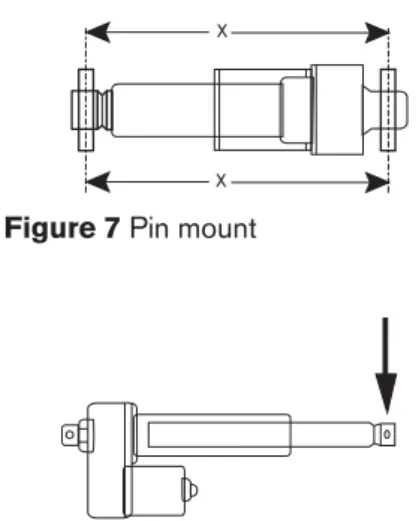
General Mounting Information
Warner Linear actuators are quickly and easily mounted by slipping pins through the holes at each end of the unit and into the brackets on the machine frame and load to be moved.Use of solid pins provide maximum holding capability with a retaining ring or cotter pin on each end to prevent the solid pin from falling out of the mounting bracket (it is best to avoid roll pins and spring pins).
Mounting pins must be parallel to each other as shown above. Pins which are not parallel can cause excess vibration or actuator binding.
Ensure that mounting pins are supported at both ends. Cantilevered mounting is unacceptable. Failure to provide proper support will shorten unit life.
Loads should act along the axis of the actuator. Off-center loads may cause binding and lead to premature unit failure.
Do not attempt to mount M-Track or A-Track actuators by the cover tube. The tube is not designed to support the forces required for tube mounting.
All actuator mounting supports must be capable of withstanding the load and torque developed when the unit extends or retracts. Restraining torque values are also provided with the details on each unit.
M-Track Torque created 2,24 Nm All others Torque created 11,2 Nm X X Cantilever Mount Wrong Right Yoke Mount Load Actuator Axis Load Right Wrong
It is very important to use the right cable size in order to supply enough current to the actuator. Otherwise we may face a huge voltage drop which will affect the operation speed and the motor lifetime. Please find below a guide line for the cable size :
Wire section Current Remark (mm²) (A)
1,5 16
2,5 20* *or 16 A for long
lead length