Air Force Institute of Technology
AFIT Scholar
Theses and Dissertations Student Graduate Works
3-26-2015
Fingerprinting Software Defined Networks and
Controllers
Zachary J. Zeitlin
Follow this and additional works at:https://scholar.afit.edu/etd
This Thesis is brought to you for free and open access by the Student Graduate Works at AFIT Scholar. It has been accepted for inclusion in Theses and Dissertations by an authorized administrator of AFIT Scholar. For more information, please [email protected].
Recommended Citation
Zeitlin, Zachary J., "Fingerprinting Software Defined Networks and Controllers" (2015).Theses and Dissertations. 73. https://scholar.afit.edu/etd/73
FINGERPRINTING SOFTWARE DEFINED NETWORKS AND CONTROLLERS
THESIS
Zachary J. Zeitlin, 2nd Lt, USAF AFIT-ENG-MS-15-M-067
DEPARTMENT OF THE AIR FORCE AIR UNIVERSITY
AIR FORCE INSTITUTE OF TECHNOLOGY
Wright-Patterson Air Force Base, Ohio
DISTRIBUTION STATEMENT A:
The views expressed in this thesis are those of the author and do not reflect the official policy or position of the United States Air Force, the Department of Defense, or the United States Government.
This material is declared a work of the U.S. Government and is not subject to copyright protection in the United States.
AFIT-ENG-MS-15-M-067
FINGERPRINTING SOFTWARE DEFINED NETWORKS AND CONTROLLERS
THESIS
Presented to the Faculty
Department of Electrical and Computer Engineering Graduate School of Engineering and Management
Air Force Institute of Technology Air University
Air Education and Training Command in Partial Fulfillment of the Requirements for the Degree of Master of Science in Cyber Operations
Zachary J. Zeitlin, B.S.C.S. 2nd Lt, USAF
March 2015
DISTRIBUTION STATEMENT A:
AFIT-ENG-MS-15-M-067
FINGERPRINTING SOFTWARE DEFINED NETWORKS AND CONTROLLERS THESIS Zachary J. Zeitlin, B.S.C.S. 2nd Lt, USAF Committee Membership: Barry E. Mullins, Ph.D. Chair Timothy H. Lacey, Ph.D. Member Kenneth M. Hopkinson, Ph.D. Member
AFIT-ENG-MS-15-M-067
Abstract
Software Defined Networking (SDN) transforms a network from a calcified collection of hardware into a logically centralized and programmable method of interconnectivity.
Changing the networking paradigm shifts a network‘s security posture. Changes
visible to a host connected to the network include small latency differences between
a traditional network environment and an SDN environment. This thesis aims to
reliably distinguish SDN environments from traditional environments by observing latency behavior. Additionally, this thesis determines whether latency information contributes to the unique fingerprint of SDN controllers. Identifying the controller software gives an adversary information contributing to a network attack.
An SDN and traditional network environment consisting of two hosts, one switch, and one controller are created. Within both environments, packet Round-Trip Time (RTT) values are compared between SDN and traditional environments to determine if both sets differ. Latency analysis is used to observe features of an SDN controller. Collected features contribute to a table of information used to uniquely fingerprint an SDN controller.
Results show that packet RTTs within a traditional network environment significantly (p-value less than 1.0×10⁻¹⁵) differ from from SDN environments. The predicted controller
inactivity timeout within the simulated environment differs from the true timeout by a mean value of 0.44956 seconds. The emulated environment shows that the observed inactivity timeout depends on the network switch implementation of the controller‘s set value, leading to incorrect observed timeouts. Within the SDN environment, the host is not able to directly communicate with the SDN controller, leading to an inability to collect the number of features needed to uniquely identify the SDN controller.
Acknowledgments
I am absolutely grateful for my thesis advisor, Dr. Barry Mullins for his leadership in ensuring my successful development through academic achievement. I also thank Dr. Timothy Lacey and Dr. Kenneth Hopkinson for their motivation towards challenging research and insights in critical thinking.
Ultimately I thank the Lord for equipping me with an intense desire for discovery. He instils my curiosity and intellect for His glory, and all I have comes from Him.
Table of Contents Page Abstract . . . iv Acknowledgments . . . v Table of Contents . . . vi List of Figures . . . ix List of Tables . . . xi
List of Acronyms . . . xiii
I. Introduction . . . 1
1.1 Background . . . 1
1.2 Problem Statement . . . 2
1.3 Goals and Hypothesis . . . 3
1.4 Approach . . . 3
1.5 Assumptions . . . 3
1.6 Contributions . . . 3
1.7 Thesis Overview . . . 4
II. Literature Review . . . 5
2.1 Software Defined Networking Defined . . . 5
2.1.1 The Forwarding Plane . . . 6
2.1.2 The Control Plane . . . 7
2.1.3 The Management Plane . . . 8
2.1.4 Separation of Planes . . . 8 2.2 SDN Components . . . 9 2.2.1 SDN Protocol . . . 9 2.2.1.1 OpenFlow . . . 9 2.2.1.2 DevoFlow . . . 14 2.2.2 Controllers . . . 14 2.2.3 Switches . . . 18 2.2.4 Applications . . . 19 2.3 SDN Growth . . . 20 2.4 SDN Security Concerns . . . 21
Page
2.5 SDN Security Applications . . . 23
2.5.1 Traffic Anomaly Detection using SDN . . . 23
2.5.2 DDoS Flooding Attack Detection . . . 24
2.5.3 Intrusion Prevention System with SDN . . . 25
2.5.4 Modular Security Services . . . 25
2.5.5 Moving Target Defense using SDN . . . 26
2.6 SDN and Latency Analysis . . . 26
2.7 SDN Applied to Network Security . . . 28
III. Methodology . . . 29
3.1 Problem Definition . . . 29
3.2 Goals and Hypothesis . . . 30
3.3 Approach . . . 30
3.3.1 Overview . . . 30
3.3.2 Features . . . 33
3.4 Experiments . . . 35
3.4.1 Experiment 1: Verify SDN Environment . . . 35
3.4.1.1 Experiment 1 Background . . . 36
3.4.1.2 Assumptions . . . 39
3.4.1.3 Parameters . . . 39
3.4.1.4 Hypothesis . . . 39
3.4.1.5 Experiment Design . . . 40
3.4.2 Experiment 2: Determine Flow Inactivity Timeout . . . 44
3.4.2.1 Experiment 2 Background . . . 44
3.4.2.2 Assumptions . . . 45
3.4.2.3 Parameters . . . 45
3.4.2.4 Hypothesis . . . 47
3.4.2.5 Experiment Design . . . 47
3.4.3 Experiment 3: Determine the Flow‘s Hard Timeout . . . 51
3.4.3.1 Experiment 3 Background . . . 52
3.4.3.2 Assumptions . . . 52
3.4.3.3 Parameters . . . 52
3.4.3.4 Hypothesis . . . 54
3.4.3.5 Experiment Design . . . 54
3.4.4 Experiment 4: Fingerprint SDN Controller . . . 58
3.4.4.1 Assumptions . . . 58
3.4.4.2 Parameters . . . 59
3.4.4.3 Hypothesis . . . 59
Page
IV. Results and Analysis . . . 67
4.1 Experiment 1 Results and Analysis . . . 67
4.1.1 Simulation Data . . . 67 4.1.1.1 Analysis . . . 68 4.1.1.2 Other Observations . . . 72 4.1.2 Hardware Data . . . 74 4.1.2.1 Analysis . . . 74 4.1.2.2 Other Observations . . . 77
4.2 Experiment 2 Results and Analysis . . . 77
4.2.1 Simulated Data . . . 77 4.2.1.1 Analysis . . . 79 4.2.1.2 Other Observations . . . 82 4.2.2 Hardware Data . . . 83 4.2.2.1 Analysis . . . 85 4.2.2.2 Other Observations . . . 86
4.3 Experiment 3 Results and Analysis . . . 89
4.3.1 Simulated Data . . . 89 4.3.1.1 Analysis . . . 91 4.3.1.2 Other Observations . . . 93 4.3.2 Hardware Data . . . 93 4.3.2.1 Analysis . . . 96 4.3.2.2 Other Observations . . . 97
4.4 Experiment 4 Results and Analysis . . . 98
4.4.1 Result . . . 98
4.4.2 Observations . . . 99
V. Conclusions . . . 103
5.1 Research Conclusions . . . 103
5.1.1 Goal #1: Construct a table of features . . . 103
5.1.2 Goal #2: Verifying feature extraction . . . 103
5.2 Research Significance . . . 104
5.3 Future Work . . . 105
List of Figures
Figure Page
2.1 SDN Planes . . . 6
2.2 SDN Packet-In and Packet-Out Events . . . 12
2.3 SDN Packet-In and Packet-Out Events . . . 12
2.4 OpenFlow v1.0 Packet-In Structure . . . 13
2.5 OpenFlow v1.0 Packet-Out Structure . . . 14
3.1 SDN Controller Fingerprinting Process . . . 31
3.2 Client versus Administrator SDN Controller Visibility . . . 32
3.3 OpenFlow Protocol Feature Extraction Points . . . 34
3.4 Path of an Initial ICMP Echo Request and Response . . . 38
3.5 Path of a Subsequent ICMP Echo Request and Response . . . 38
3.6 Mininet Simple Network . . . 42
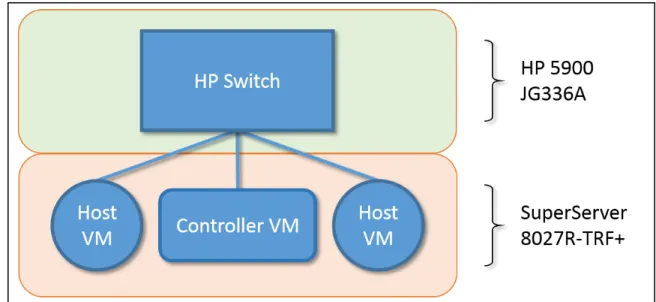
3.7 Hardware Simple Network . . . 44
3.8 Ensuring Value Uniqueness . . . 65
4.1 Ping Ratios with Simulated SDN Controllers . . . 70
4.2 Example Ping Ratios . . . 73
4.3 Ping Ratios with Emulated SDN Controllers . . . 76
4.4 Inactivity Timeout Delta Histogram (Outliers Included) . . . 80
4.5 Inactivity Timeout Delta Histogram (Outliers Excluded) . . . 81
4.6 Inactivity Timeout Delta with HP Switch Histogram . . . 84
4.7 HP Switch Flow State With Ryu Controller Attached . . . 88
4.8 HP Switch Flow State With Iris Controller Attached . . . 88
4.9 Hard Timeout Delta Histogram (Outliers Included) . . . 91
Figure Page 4.11 Hard Timeout Deltas Using The Hardware HP Switch (Outlier Included) . . . . 95 4.12 Hard Timeout Deltas Using The Hardware HP Switch (Outliers Excluded) . . . 96
List of Tables
Table Page
2.1 OpenFlow v1.3.4 Match Fields . . . 10
2.2 OpenFlow v1.3.4 Available Flow Statistics . . . 11
3.1 List of Features and Collection Times . . . 35
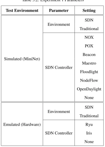
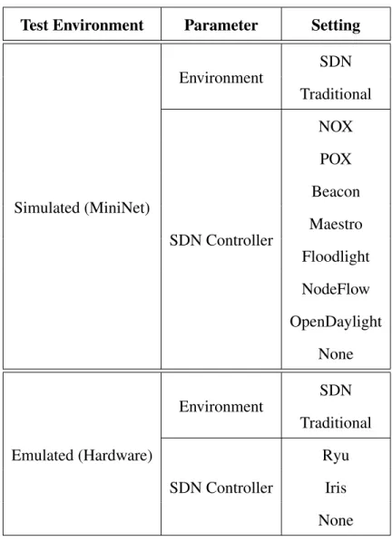
3.2 Experiment 1 Parameters . . . 40
3.3 Experiment 1 Parameters Held Constant . . . 41
3.4 Experiment 2 Parameters . . . 46
3.5 Experiment 2 Parameters Held Constant . . . 47
3.6 Interpretation ofZS coreValues . . . 49
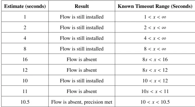
3.7 Discovering Inactivity Timeout (With Precision of 0.5 Seconds) . . . 50
3.8 Experiment 3 Parameters . . . 53
3.9 Experiment 3 Parameters Held Constant . . . 54
3.10 Discovering Hard Timeout (With Precision of 0.5 Seconds) . . . 56
3.11 Experiment 3 Test Cases . . . 57
3.12 Experiment 4 Parameters . . . 59
3.13 Experiment 4 Parameters Held Constant . . . 60
3.14 List of Keys . . . 62
3.15 SDN Controller Features . . . 63
3.16 Partial List of OpenFlow Packet Types . . . 64
4.1 Experiment 1 Sample Data . . . 68
4.2 Experiment 1 Summary Data . . . 69
4.3 Experiment 1 T-Test Results . . . 71
4.4 Experiment 1 RTT Values Below Maximum Traditional RTT Value . . . 73
Table Page
4.6 Experiment 1 Hardware Summary Data . . . 75
4.7 Experiment 1 T-Test Results . . . 77
4.8 Experiment 2 Sample Data . . . 78
4.9 Experiment 2 Summary Data . . . 79
4.10 Discovering Inactivity Timeout of 2.625 (With Precision of 0.25 Seconds) . . . 82
4.11 Experiment 2 Sample Hardware Data . . . 83
4.12 Experiment 2 Summary Hardware Data . . . 84
4.13 Experiment 2 Hardware Data Subset . . . 85
4.14 Experiment 2 Hardware Data Subset . . . 87
4.15 Experiment 3 Sample Data . . . 90
4.16 Experiment 3 Summary Data . . . 90
4.17 Experiment 3 Sample Hardware Data . . . 94
4.18 Experiment 3 Summary Hardware Data . . . 95
4.19 List of Features . . . 101
List of Acronyms
Acronym Definition
ABf Average Bytes per flow
ADf Average Duration of the flow
ADS Anomaly Detection Systems
APf Average Packets per flow
API Application Programming Interface
ARP Address Resolution Protocol
CLI Command-Line Interface
CPU Central Processing Unit
csv comma-separated values
DDoS Distributed Denial of Service
DoS Denial of Service
GDP Growth rate of Different Ports
GPU Graphic Processing Unit
GSf Growth rate of Single-flows
ICMP Internet Control Message Protocol
IDS Intrusion Detection System
IPS Intrusion Prevention System
ISP Internet Service Provider
LLDP Link Layer Discovery Protocol
MAC Media Access Control
OF-RHM OpenFlow Random Host Mutation
PPf Percentage of Pair-flows
Acronym Definition
rps requests per second
RTT Round-Trip Time
SDN Software Defined Networking
SOM Self-Organizing Map
STP Spanning Tree Protocol
TRW-CB Threshold Random Walk with Credit Based rate limiting
vIP virtual Internet Protocol address
FINGERPRINTING SOFTWARE DEFINED NETWORKS AND CONTROLLERS
I. Introduction
1.1 Background
Cyber warfare is present in the United States’ 2014 quadrennial defense review, and the act of countering cyber attacks is paramount for investment [1]. The necessity of network infrastructure parallels the requirement in ensuring a sufficient defense against adversaries willing to exploit any vulnerability. From corporate entities losing sensitive client information, money, and customer trust, to nation states capturing national defense intelligence, cyber efficacy remains prevalent in today’s society. The threat of cyber attacks and interest in securing our cyber borders continually increases as is shown in both current events as well as from security analysts [2][3][4][5].
Enhancing cyber security starts with maintaining an inventory of authorized and unauthorized devices considering attackers are constantly scanning for new unprotected systems that join a potentially sensitive network [6]. In addition to new systems, new technologies that join the network are also lucrative for attackers given any lack of
documented security testing may keep unknown vulnerabilities from discovery. New
technology presents new avenues for zero-day engineering, which allows an adversary unmitigated capabilities during the life of the zero-day [7].
New technology currently growing in the network environment includes the use of Software Defined Networking (SDN). SDN promises to remove the vendor-specific requirements placed on a network administrator by transforming network switches into simple packet forwarding devices, while placing the brains of the network into logically
not concern themselves with the underlying vendor-specific implementations in order to accomplish high-level abstract goals. Configuration is simplified. Considering the technology is new, security implications for the increased flexibility have not been fully tested. It is important to identify how the network changes with this radical shift in network topology. Determining what the adversary gains from the network administrators‘ increased convenience allows defensive updates to guard against cyber threats.
1.2 Problem Statement
This research attempts to identify information that is unintentionally offered to
a network attacker when SDN is used within a small network, and demonstrates the feasibility of uniquely identifying the software managing the SDN environment. With positive identification of the software controlling the SDN environment (a process known as fingerprinting), an attacker can then search for existing vulnerabilities or attempt to develop custom attacks against the logically centralized software. Preventing an attacker’s discovery of the network controller assists in thwarting the attacker’s reconnaissance, ultimately inhibiting the attacker’s capabilities. If an attacker is unable to uniquely identify a target, then the list of available vulnerabilities at the attacker’s disposal is limited, and the attacker’s threat is minimized. Focusing on assessing whether fingerprinting is possible, this research attempts to identify first when SDN is deployed, and then proceeds to gather intelligence in the form of unique features that describe the SDN controller software. The end of this collection of features occurs when the SDN software is successfully fingerprinted.
The methods of collecting data are restricted to the methods available to an attacker. An attacker is assumed to have a presence in the network in the form of a connection to the network switching fabric. The attacker can also communicate to other end hosts on the network, including a host that is another point of presence for the attacker (i.e., the attacker can have two points of presence on the network to communicate between).
1.3 Goals and Hypothesis
The objective of this thesis is to develop and evaluate a process for extracting features to uniquely identifying the controller supporting an SDN environment. The first goal of this research is to construct a set of features extensive enough to uniquely identify each known SDN controller. The next goal includes ensuring that each feature is obtainable by a client connected to the SDN environment. It is hypothesized that a process can be created that adds each new SDN controller into a table of SDN controller features, and that this table can be used to identify an unknown SDN controller discovered in an SDN environment by a client connected to that environment.
1.4 Approach
A simulation of a simple SDN environment is created using MiniNet [25]. Features are programmed into the SDN controller software and then observed by a client connected to the SDN environment. The observed features and true values are compared for accuracy. The same process is performed using network equipment to validate the results obtained from the simulated environment.
1.5 Assumptions
The experiments within this research assume a client has access to a port connected to a network environment. Once an SDN software controller is uniquely identified, the action of searching for documented vulnerabilities and exploiting the SDN controller is beyond the scope of this research. Research is limited to information gathering.
1.6 Contributions
This thesis contributes to the body of research in SDN. Specific contributions include a process for distinguishing SDN environments from traditional environments, the set of features observable by a client within an SDN environment, as well as the process for
fingerprinting SDN controllers through the collection and categorization of features in a feature table.
1.7 Thesis Overview
This thesis is organized into five chapters. Chapter 2 defines SDN and presents relevant research needed to understand new threats created by the addition of SDN
technology. The methodology for evaluating the fingerprinting process for an SDN
environment is explained in Chapter 3. The experimental results and analysis of collected data are presented in Chapter 4. Finally, Chapter 5 summarizes this research and concludes with the results of each experiment, along with an explanation of the significance and suggested future work.
II. Literature Review
T
his chapter defines SDN, and reviews the relevant bodies of research needed tounderstand and implement an SDN environment. Section 2.1 introduces a high-level concept of SDN. Section 2.2 defines each component that combine to make up a software-defined network. Section 2.3 explains current uses, growth, and potential of future SDN applications. Next, Section 2.4 provides relevant research in Software Defined Networking specific to network security concerns, followed by Section 2.5, which describes current research in security applications designed to mitigate various security concerns. Section 2.6 reviews research conducted on the latency effects of adopting SDN as well as the potential for latency analysis in gathering information about the SDN environment. This chapter concludes with an explanation of how SDN can be constructed within a network to apply these mitigating techniques.2.1 Software Defined Networking Defined
Within a computer network, switching devices contain three abstractly organized
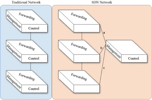
services known as planes [9]. As shown in Figure 2.1, these planes consist of the
forwarding plane (also referred to as the data plane), the control plane, and the management plane. Within Figure 2.1, the left portion shows a traditional network where each box represents a switching device that independently contains all three previously described planes. The software-defined network on the right shows three switches (which only require
forwarding capabilities) connected to a controller (which provides control/management
plane functionalities). It is the communication between these planes that results in the internals of a network switch. The three planes are typically found within a single device. SDN aims at separating the control plane (inclusive to the management plane) from the
forwarding plane, and placing this functionality within a separate device known as a controller.
Figure 2.1: SDN Planes
2.1.1 The Forwarding Plane.
The forwarding plane of a switch receives incoming Ethernet frames, and forwards those frames onto a port determined by rules created by the control plane. When a frame is first received on the wire to a specific port of a switch, the forwarding plane calculates various sanity checks for the incoming frame. Such sanity checks include sizing, alignment,
and checksum validation [9]. A response to a failed sanity check is implementation
dependent, but often results in the frame being dropped. A successful sanity check results in the frame proceeding to the forwarding lookup process. This lookup process is known as the “fast-path” for frames because the lookup process‘ purpose is specialized in moving the frame to the correct destination quickly, needing only to extract the destination information from the frame [9].
The forwarding lookup process can be implemented in many ways depending on a vendor‘s proprietary design. The implementation possibilities include performing a lookup within software, hardware-accelerated software (e.g., Graphic Processing Unit (GPU)s or Central Processing Unit (CPU)s), commodity hardware (i.e., a network processor), and specialized hardware (i.e., application-specific integrated circuits).
The forwarding process concludes with a set of specific actions. Actions include forwarding the frame, replicating the frame, dropping the frame, modifying the frame, counting the frame (i.e., keeping a record of frame information for statistical purposes), and queuing the frame. The frame may also be destined for a process running locally on the switch (e.g., for Link Layer Discovery Protocol (LLDP), or Spanning Tree Protocol (STP) updates), in which case the frame will be “punted” from the forwarding lookup process and processed by the route processor [9]. The act of moving a locally-destined frame is accomplished through an internal communication channel.
In the event that a destination port does not match any forwarding rule entry for a particular frame, SDN protocol dictates that the frame is then sent to the control plane for further processing [9][10][11]. The communication between the forwarding plane and the control plane is accomplished through a standardized protocol.
2.1.2 The Control Plane.
The control plane is responsible for creating the forwarding table that is utilized by the forwarding plane to send a packet from source (ingress) port to destination (egress) port. This table of entries is populated once a stable topology of the network is established. Methods of informing the control plane about network topology include programming the logic directly or through network protocols (such as link-state or distance-vector algorithms). A packet arriving at the control plane from the forwarding plane is processed, whereby the packet‘s information may result in a modification of the forwarding plane‘s forwarding table.
2.1.3 The Management Plane.
The control plane is considered a superset of the management plane, which is responsible for network administration that may result in control plane behavior modification due to administrative policies (such as enforcing access control lists). While the control plane modifies the forwarding table of the forwarding plane, the management plane manages the policies that are enforced by the control plane.
2.1.4 Separation of Planes.
Separating the control plane from the forwarding plane allows control decisions of forwarding behavior to exist on a logically centralized, and thus easily managed, location. Instead of each network switch independently containing all three planes, the switches specialize in performing forwarding-plane functions, leaving the decision of creating rules to a separate controller running specific control-plane software. Having each switch only perform forwarding-plane functions simplifies the processor logic and has the added benefit of commoditizing the switching hardware [10].
Moving the control plane to a separate controller effectively reduces the number
of logical control planes within a network to one, rather than equal to the number
of switches in the network. By having a single control plane for multiple switches,
a network administrator can program flow-control capabilities (such as traffic-shaping)
from one logical location, rather than requiring that administrator to touch every switch independently with disparate functionality.
Additionally, other benefits of separating the control and forwarding planes typically
result from the innovation allowed by modularity: each plane can be improved
independently. Independent improvements reduce complexity, also increasing stability
within a hardware design. Technological improvements also reduce the price per
The following sections break down software-defined networking into each of its components: the protocol used between devices, the controller which coordinates network activity, and finally the individual switches that implement actions specified by the controller.
2.2 SDN Components
SDN incorporates four components that facilitate development of a programmable network with physically-separate forwarding and control planes: the protocol, controller,
network switch, and network application. There may be one or many switches
communicating with one or many controllers, yet the protocol remains standardized and consistent throughout communication.
2.2.1 SDN Protocol.
A traditional switch‘s control plane communicates with the forwarding plane directly using proprietary communication as both planes are located on the same device. In order
for different switch forwarding planes in a software-defined network to communicate with
a controller, both a physical link to the controller, and a standard communication protocol are needed. The physical link may be a point-to-point connection, or an indirect connection through several hops. This communication exists within links labelled a, b, and c in Figure 2.1.
2.2.1.1 OpenFlow.
The de facto protocol in use today is OpenFlow [11]. OpenFlow is designed to decrease the barrier to entry in experimenting with network protocols, with the additional
goal of preventing ossification of network infrastructure. OpenFlow allows protocol
experimentation by allowing the network administrator to separate production traffic from
experimental traffic. When a packet arrives at an OpenFlow compatible switch, the switch
the controller. When a controller receives a packet from an OpenFlow switch, the event is known as a “packet-in” event [9].
Table 2.1: OpenFlow v1.3.4 Match Fields
Field Description
OXM OF ETH DST Ethernet destination address
OXM OF ETH SRC Ethernet source address
OXM OF ETH TYPE Ethernet type of the OpenFlow packet payload
OXM OF IP PROTO IPv4 or IPv6 protocol number
OXM OF IPV4 SRC IPv4 source address
OXM OF IPV4 DST IPv4 destination address
OXM OF IPV6 SRC IPv6 source address
OXM OF IPV6 DST IPv6 destination address
OXM OF TCP SRC TCP source port
OXM OF TCP DST TCP destination port
OXM OF UDP SRC UDP source port
OXM OF UDP DST UDP destination port
The application running on the controller dictates how to respond to a packet-in event. The controller application informs the switch using an event known as a “packet-out” event. Responses can include dropping the packet, forwarding the packet back to the switch with information about where the packet should go, or installing a rule on the originating switch. Each rule is known as a flow entry. A flow entry informs the switch about how to handle future packets that match a set of specified fields. Installing flow entries prevents the controller from intervening on every packet and thus prevents a bottleneck. Required available matching fields for a switch to be OpenFlow compliant are included in Table 2.1.
These matching fields are parsed by the Openflow switch. An OpenFlow switch may be capable of matching on additional fields other than the required list shown in Table 2.1.
Wildcards are available for certain matching fields. An example of using wildcard matching includes aggregate flows, which are flows installed in an Openflow switch that match on multiple IP addresses. Aggregate flows can dictate a switch to have a number of ingress ports forward to a specified egress destination.
Each flow entry can be created with an idle timeout period, where the flow entry is automatically removed if zero packets match the flow entry‘s headers for the duration of the timeout period. Flow entry statistics can also be gathered by the switch as another metric or input for programming. Available flow entry statistics depend on the network switch‘s capabilities and are included in Table 2.2. When a set of fields from an inbound packet matches a particular flow entry, a corresponding action is then applied to the packet. An action can be anything within the OpenFlow specifications and includes anything from packet-mangling to simply forwarding the packet to a specified port.
Table 2.2: OpenFlow v1.3.4 Available Flow Statistics
Statistic Description
duration sec The time the flow has been alive in seconds
duration nsec The time the flow has been alive in nanoseconds beyond duration sec
priority The priority of the flow entry
idle timeout The number of seconds idle before expiration
hard timeout The number of seconds before expiration
packet count The number of packets that have traversed the flow
Figure 2.2: SDN Packet-In and Packet-Out Events
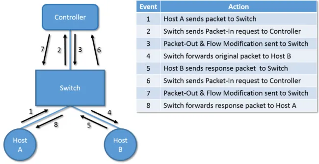
An example of the flow of communication is depicted in Figure 2.2. Within this figure, the left host creates a packet destined for the right host. The packet is sent to the switch. Without any flow rules installed, the switch does not know how to handle the packet because the packet matches no existing flow rule, and consequently the switch creates a packet-in event destpacket-ined for the controller. The structure of the packet-packet-in event is depicted packet-in Figure 2.4 [12]. The packet-in event contains the entire Ethernet frame that was sent to the switch, should the controller need to parse it. The controller application then responds to the packet-in event and constructs a packet-out event destined for the switch. The structure of the out event is depicted in Figure 2.5 [12]. The switch, responding to the packet-out event from the controller, forwards the original packet to the intended destination. If a flow is installed on the switch from the packet-out event, then future packets originating from the left host in Figure 2.2 that match the flow specification will forward to the right host without any communication with the controller (as depicted in Figure 2.3).
Figure 2.5: OpenFlow v1.0 Packet-Out Structure
2.2.1.2 DevoFlow.
Curtis et al. develop DevoFlow, another SDN protocol [13]. DevoFlow is designed in response to concerns about OpenFlow meeting the needs of high-performance networks. The granularity of OpenFlow control and visibility over flow entries requires a high rate of communication between the switch and the SDN controller, both for flow setups as well as for statistics-gathering. Such overhead limits the scalability of OpenFlow for high-performance networks. DevoFlow reduces the scalability concern by minimizing the number of flows created by the control plane. Instead of requring the control plane for every flow setup, all flows that can be determined locally by the data plane are set up by the data plane without the control plane‘s awareness. Determining which flows are worth sending to the controller, known as elephant flows (i.e., flows with high throughput and long life) becomes a variable to optimize. Simulation shows that the DevoFlow method improves throughput compared to equal-cost multi-path routing by up to 32% [13].
2.2.2 Controllers.
The network administrator programs the network control plane within the controller. The network controller is considered the network operating system; the controller provides an abstraction to the network topology much like an operating system abstracts the
provide the ability to both observe and manage network events. Several OpenFlow-compatible controller platforms are available.
Gude et al. created NOX, the first SDN controller [14]. NOX facilitates developing network applications, and thus satisfies the need of a network operating system. NOX runs on a sever, and contains a single network view that applications utilize to manage the state of the network. NOX works with the OpenFlow specification so that a standard communication protocol exists between the controller and network switches. Applications
for NOX are written in Python or C++, with speed-critical core infrastructure written in
C++.
Erickson created Beacon, the open-source OpenFlow controller written in Java [15]. Beacon makes OpenFlow applications both easy to develop and performance capable, as
it bridges the gap between the ease of Python and the performance of C++. Beacon also
allows OpenFlow applications to start and stop at runtime, giving the controller more of an operating system feel.
Zheng et al. propose an OpenFlow controller that overcomes the fact that NOX is a single-threaded system [16]. The controller, called Maestro, incorporates parallelism to address the concern that the controller could be a bottleneck. Maestro also takes advantage of batched socket write operations. Writing to the socket in batches requires less overhead than writing to the socket for each individual packet. Maestro also offers the ability to bind a worker thread to a core, which removes the overhead of moving code and data between cores, and results in increased throughput. Additionally, Maestro also allows binding an input flow request to a single working thread, keeping each request within one processor core, which reduces synchronization overhead.
A NOX controller with an input flow request rate of less than 20,000 requests per second (rps) results in an average delay of 2 ms. Increasing the request rate to the maximum throughput of NOX (i.e., 21,126 rps) increases the average delay to 17 ms. Increasing
beyond this upper-bound results in packet buffering, causing TCP to slow down, resulting in an average delay of 4.11 seconds. This is due to the fact that the controller is only capable of utilizing one CPU core. When Maestro utilizes seven threads, an input rate of 630,000 rps results in an average delay of 76 ms. An input rate exceeding the maximum throughput of Maestro (i.e., 633,290 rps) causes an average delay of 163 ms. Under loads less than 16,000 rps the average delay is 2 ms. A NOX controller has a lower packet-handling delay for requests rates lower than 16,000 rps as compared to Maestro considering the overhead applied by Maestro to allow parallelism. Maestro‘s benefits are shown when the number of requests increases, allowing flexible scalability.
Tootoonchian et al. present cbench, a tool to quantify controller performance [17]. Cbench focuses on latency when a flow is first installed on a switch, as that is the likeliest source of a performance bottleneck. Cbench emulates OpenFlow switches which then send a custom number of OpenFlow packet-in messages. When a response arrives from the controller, cbench records the delay between request and response. In addition to cbench, Tootoonchian et al. creates a multi-threaded version of NOX known as MT to test NOX, Beacon, and Maestro using the cbench tool. Similar to Maestro, NOX-MT also performs batched socket write operations to minimize the overhead of writing to a socket. Unlike Maestro, which is implemented in Java, NOX-MT is a modification
of NOX written in C++. NOX-MT also uses a modified malloc implementation that is
designed specifically for multiprocessors. The use of a multiprocessor-aware malloc allows scalability within multi-core systems. When comparing maximum throughput, NOX-MT is capable of handling greater than one million rps when utilizing four CPU cores, while Maestro and Beacon both handle less than 500 thousand rps when using four CPU cores.
Floodlight is a self-proclaimed leader of the open source SDN controllers [18]. Written in Java, Floodlight introduces a modular loading system which simplifies updates and extensions. Floodlight is developed by an open community of developers including
developers from Big Switch Networks [19]. Floodlight uses OpenFlowJ-Loxigen, a Java library generated by Loxigen [20]. Loxigen abstracts away low-level protocol details allowing an OpenFlow version to be easily defined. Any update to the OpenFlow version requires only a new Loxigen file defining the OpenFlow version through a common Application Programming Interface (API). The use of Loxigen by Floodlight prevents obsolescence due to OpenFlow version updates.
Lee et al. create Iris, a controller designed specifically to address the requirement of availability while allowing network scalability [21]. The architecture of IRIS allows multiple servers benefiting a controller cluster, using server resources on demand. Iris splits a network into independent “unit SDN networks” that are interoperable through a mechanism operated by a controller. Each unit SDN network has a scalable middleware the operates on top of the Openflow protocol, and can be controlled by a separate controller instance, providing horizontal scalability. Using cbench, Lee et al. model 100,000 hosts on an Intel server with a Xeon X5690 processor (having 3.47 GHz and 6 physical cores) and 64GB of RAM [17]. Analyzing flow processing performance demonstrates that the Iris controller outperforms Floodlight by a factor of 2.5 (i.e., the maximum number of flows maintainable is greater by a factor of 2.5). Floodlight is chosen for comparison as it is the most popular Java-based open-source Openflow controller [18].
While various research attempts to increase the efficiency of logically and physically centralized SDN controllers, other research has proposed physically distributing the
controller while maintaining logical centralization. Tootoonchian et al. propose
HyperFlow, an application designed for NOX controllers that creates a distributed event-based control plane for OpenFlow applications [22]. HyperFlow pushes state information to other controllers, allowing all controllers to have the same view of the network. Considering each controller has a uniform view of the network, each controller is locally
messaging paradigm to allow cross-controller communication. The publish/subscribe system is implemented using WheelFS, a distributed file system. Using WheelFS, channels between controllers are represented using directories, and messages are represented using files. HyperFlow polls directories to update changes made by other controllers.
Evaluation of HyperFlow performance is based on the window of inconsistency (i.e., the amount of time for controllers to agree on a view of the network) as load increases. The window of inconsistency is dependent on how fast HyperFlow and WheelFS are together capable of reading and writing files. HyperFlow is able to achieve a bounded window of inconsistency among controllers so long as fewer than 1000 link state changes occur per second (i.e., fewer than 1000 switches or hosts join or leave the network per second).
With the number of controller platforms increasing, it becomes necessary to compare
various controllers. Shalimov et al. present an analysis of efficiencies of various open
source SDN controller platforms using a new framework called hpcprobe [23]. The
efficiency metric is determined by factors including performance (i.e., throughput and
latency), scalability, reliability (measured through number of failures), and security (tested through the use of malformed Openflow packets). Hcprobe emulates an SDN environment, and allows custom tests through the use of its API written in Haskell. The SDN controllers
tested include NOX, POX, Floodlight, Beacon, MuL, Maestro, and Ryu. In testing
throughput, 32 switches are emulated with 105 hosts per switch. Beacon achieves the
highest average number of flows per second as the number of threads increases. When testing reliability, MuL and Maestro drop controller-bound packet-in messages under the test load. When testing security through the use of a malformed Openflow header, Maestro and NOX crash upon receiving messages with incorrect length field values.
2.2.3 Switches.
Greenhalgh et al. describe two trends within network topologies: an increase in the proliferation of middle-boxes, and the commoditization of servers and switches [24].
Middle-boxes include any device sitting between switches, often providing transport-layer functions up to application-transport-layer functions (e.g., web proxies, firewalls, intrusion detection/prevention, load balancers, etc.). The increase in switch capabilities combined
with a reduction in cost leads to the consolidation of middle-box capabilities. This
consolidation replaces middle-boxes with a single device: the programmable switch. The benefits of consolidation include a reduction in equipment and maintenance costs, dynamic resource allocation, and an increased tolerance of failures. Rather than having separate hardware with dedicated (and thus rigid) functionality, the increased switch performance allows that functionality to be programmed dynamically into the switch at the network administrator‘s discretion, preventing the need for separate dedicated devices. Tolerance of failures comes from the fact that cheaper commodity hardware can be made redundant and easily hot-swapped. In order for switches to contribute to a software-defined network, they must be compliant with the protocol utilized by the controllers. The requirement for SDN-capable switches limits the availability of switches to those compliant with the OpenFlow specification.
2.2.4 Applications.
An SDN application runs locally on the controller and dictates either proactively
or reactively how forwarding tables are populated. An emulated environment for
SDN applications allows a network administrator to test whether a network application fulfills specific requirements. Additionally, an emulated environment allows a network administrator to test the SDN application before installing it onto production controllers. Lantz et al. developed Mininet, a system that generates an emulated environment which allows rapid prototyping for large networks [25]. Mininet addresses the problem of a high barrier to entry for designing a new network architecture. Mininet is designed to be flexible, deployable, interactive, scalable, realistic (i.e., the behavior observed in the emulated
environment should represent what would be expected in a production environment), and shareable (i.e., easily encapsulated and installed).
Mininet offers a Command-Line Interface (CLI) that allows the user to easily create
an arbitrary network with virtual hosts attached to any number of OpenFlow switches and a controller of any type. Mininet also contains a Python API which allows custom scripting for experimentation. One notable limitation of Mininet is the fact that software forwarding speeds cannot match the O(1) forwarding time of hardware lookup tables, which may skew packet forwarding-rate statistics.
Gupta et al. developed a simulation tool known as fs-sdn, which is designed for greater scalability than Mininet [26]. Rather than basing the simulated network abstraction around each packet, fs-sdn‘s unit of measure is a flowlet. A flowlet represents the number of flows emitted over a period of time (e.g., within a period of 150 milliseconds, 1 or more packets traversed the emulated device). The higher level of abstraction allows greater speed and accuracy than current packet-level simulators (e.g., ns-2 and ns-3) [27][28]. Results show that fs-sdn remains consistent across various topologies and rate configurations, while
Mininet loses accuracy as both load increases from 10 Mb/s to 100 Mb/s, and with an
increase in the number of nodes within the emulated network. Accuracy is determined by comparing byte, packet, and flow counts recorded by each platform.
2.3 SDN Growth
Increasing interest in SDN capabilities among SDN researchers as well as growing applications of SDN environments emphasizes the importance of security as its widespread adoption presents a more lucrative target for network attackers. Google is one example of a major corporation taking advantage of SDN capabilities. Jain et al. present B4, a software-defined network connecting Google‘s data centers together across continents
[29][30]. Specific needs inclusive to high bandwidth, dynamic traffic demands, and full
to accomplish the needs of B4. In addition to Google, the SDN market is expected to grow beyond $35 billion by April 2018 [31]. The rate of growth is shown by the fact that SDN technology sales have increased from $10 million in 2007 to $252 million in 2012 [31].
2.4 SDN Security Concerns
Considering the age of SDN, concerns exist regarding the security implications
imposed by the transformation of an entire networking paradigm. Kl¨oti et al. use
STRIDE and attack tree modeling methods to evaluate the security of an emulated SDN network [32][33][34]. When testing the potential for denial of service, the POX-controlled MiniNet simulated SDN environment is utilized with an increased timeout value to allow greater flow entries. The number of lost packets increases consistently with an increasing flow timeout value (and consequently an increase in table overflows). When testing for information disclosure, Kl¨oti et al. compare the time it takes for an initial connection of a server to the time it takes for a subsequent connection with the same network server.
A drastic difference in delays denotes a new flow entry, which suggests no other client
already has an established session with the service of interest. This type of information disclosure only exists when flow aggregation is utilized. Kl¨oti et al. suggest rate limiting, flow aggregation, attack detection, and access control mechanisms to mitigate any Denial of Service (DoS) vulnerabilities. Kl¨oti et al. also suggest proactive strategies inclusive to randomizing response times as well as attack detection methods in order to mitigate potential information disclosure vulnerabilities.
Scott-Hayward et al. present an in-depth survey on research related to security
implications of SDN [35]. Within the survey, two schools of thought regarding security in SDN environments exist. The first states that the programmability of the new technology allows a more secure environment as well as a centralized view of the network security posture. The second states that the centrality and other new features of SDN expose the network to a new vector of attacks.
Shin and Gu propose a feasibility study in attacking SDN environments [36]. The attacks include fingerprinting an SDN environment as well as using a DoS attack against an SDN environment. Fingerprinting involves the use of SDN Scanner, which changes the header field in two packets, and collects the RTT values for these packets. From the RTT values, Shin and Gu can determine whether an externally-located network is an SDN environment with a success rate of 85.7%. The DoS analysis tests against Open VSwitch installed on a separate Linux host, with a switch flow table capacity of 1500 flows entries. Shin and Gu show with the emulated SDN environment that it takes ten seconds with 200
packets per second at a bandwidth of 0.75 Mbps to effectively consume the resources of
the control plane and the data plane.
Documented vulnerabilities already exist with current SDN controllers. Dover
presents two, both targetting the Floodlight SDN controller [37][38]. The first vulnerability is a switch table vulnerability, where malformed Openflow messages allow an attacker to cause full CPU utilization on the controller, ultimately denying controller functionality. The second vulnerability is another DoS vulnerability that involves tearing down the connection between the targeted switch and controller. Without communication between the controller and the switch, the implementation of the switch dictates whether the network switch falls back to traditional forwarding techniques or follows another response to the DoS attack.
Diego et al. present seven threat vectors regarding the introduction of the SDN
environment [39]. The first threat vector includes forged or faked traffic flows, which
target switches and controllers in an SDN environment. The second threat vector includes attacks on vulnerabilities specific to Openflow network switches. The third threat vector is an attack on the control plane communication (i.e., the link between the network switch and the SDN controller). The fourth threat vector includes vulnerabilities existing in the SDN controller, given the controller is software potentially consisting of numerous faults. The fifth threat vector is the lack of verification between the controller and the
management applications written on them. The sixth threat vector includes vulnerabilities within administrative stations that exist within an exploitable network. The final threat vector is the lack of trusted resources for forensics and remediation for when an attack is detected.
2.5 SDN Security Applications
Numerous applications have been created that apply the SDN architecture towards
providing security to an existing network. The logically centralized nature of the
control plane allows an additional component that is taken advantage of through security applications: a view of the entire network. Not only does SDN allow a singular view of the entire network, but SDN also allows a controller to change that view, lowering the barrier to creativity in network programming. Security applications include anomaly detection, Distributed Denial of Service (DDoS) prevention, Intrusion Prevention System (IPS), modular security, and a moving target defense.
2.5.1 Traffic Anomaly Detection using SDN.
Mehdi et al. utilize SDN to revisit Anomaly Detection Systems (ADS), a security
application that was explored “rather unsuccessfully” in the past [40]. Mehdi et al.
differentiate between the network core and the network edge. The network core consists
of hardware that makes up the backbone of the Internet. The core does not directly touch the end devices, but rather facilitates the end device communication by connecting
sub-networks to each other. The network edge includes switching hardware that directly
connects to an endpoint device or endpoint network. The method explained in [40]
involves moving four different ADS algorithms from the network core to the network
edge. Before SDN, this was difficult as switching hardware ran proprietary software that
was not modifiable. By replacing proprietary switches at the network edge with openly-programmable switches adherent to the OpenFlow specification, ADS can be moved closer to the anomalous sources (i.e., the network edge).
Moving ADS closer to the anomalous sources offers different magnitudes of benefits depending on the ADS algorithm implemented. One ADS algorithm implemented was the Threshold Random Walk with Credit Based rate limiting (TRW-CB) algorithm. TRW-CB is based on the notion that connection attempts are more likely to succeed when originating from benign hosts rather than from malicious hosts. Implementing the TRW-CB algorithm at the network edge (using a home network dataset) with SDN was shown to achieve a 90% accuracy of detection, with a false positive rate of 0% to 4%. Moving this algorithm to the network core (using an Internet Service Provider (ISP) dataset) resulted in an accuracy of 85% detection rate with a false positive rate of 11%.
2.5.2 DDoS Flooding Attack Detection.
Braga et al. use the per-flow statistics already stored by OpenFlow compliant switches to detect a DDoS [41]. The detection process involves three modules: the flow collector module, the feature extractor module, and the classifier module. The flow collector module requests flow statistics from OpenFlow switches at an interval specified by the controller application. Using flow statistics rather than packet header information decreases overhead. The feature extractor module grabs data relevant in detecting a DDoS flooding attack. The classifier module uses a Self-Organizing Map (SOM), a type of neural network, to classify whether the polled data consists of a DDoS flooding attack.
The features worth extracting from flow statistics include the Average Packets per flow (APf), the Average Bytes per flow (ABf), the Average Duration of the flow (ADf) (i.e., the flow‘s lifetime), the Percentage of Pair-flows (PPf), the Growth rate of Single-flows (GSf), and the Growth rate of Different Ports (GDP). All flow statistics are natively
logged by OpenFlow switches, preventing the need to install custom software for traffic
statistic logging. Using flow statistics resulted in a detection rate greater than 98%, while taking a CPU time of 154 seconds to extract 6 flow features on a 1.8 GHz, dual core CPU with 2 GB of RAM. Feature extraction methods using packet header information required
9 features (taking a CPU time of 237 seconds to extract on a 2.66 GHz, dual core CPU with 3.5 GB of RAM).
2.5.3 Intrusion Prevention System with SDN.
Xing et al. propose an IPS that uses OpenFlow to perform countermeasures on
flows identified by Snort‘s Intrusion Detection System (IDS) engine [42]. Working in
tandem with an iptables firewall, an IDS effectively becomes an IPS. Such an IPS system
suffers from latency issues, accuracy issues (in terms of the number of false positives), and flexibility. While [42] claims to compare SnortFlow with an iptables-based IPS, no data is shown directly comparing these two IPS systems.
2.5.4 Modular Security Services.
Shin et al. present FRESCO, an OpenFlow application development framework that utilizes standardized modules to facilitate security detection and mitigation development
[43]. FRESCO overcomes an information deficiency challenge through the use of a
database module (FRESCO-DB) that simplifies storage of key state tracking information. Such state tracking information is normally not collected by OpenFlow controllers, yet is often required to develop security applications. Example data that exists in the FRESCO-DB module includes a TCP connection status as well as IP reputation. Replicating open-source network security applications using FRESCO results in an order of magnitude fewer lines of code. FRESCO also deploys garbage collection, which checks if an OpenFlow switch is nearing the capacity of flow entries for the switch, and evicts the least active flow. Garbage collection in FRESCO minimizes resource utilization by reducing the number of flow entries within each OpenFlow switch. One drawback to FRESCO exists in the setup time required to install flows. FRESCO applications require additional setup time to install a flow entry ranging from 0.5 milliseconds to 10.9 milliseconds more than the time it takes for the default NOX controller to install a flow entry. The additional setup time was
credited to using an emulated environment running on a virtual machine, but this theory was not tested.
2.5.5 Moving Target Defense using SDN.
Jafarian et al. take advantage of the fact that the controller monitors and manipulates the entire network from a central vantage point, and use the centralized controller to provide a moving target defense against network attacks [44]. The technique, called OpenFlow Random Host Mutation (OF-RHM), assigns a random virtual Internet Protocol address (vIP) for each end hosts within a network, while maintaining a map of vIP to a real Internet Protocol addresses (rIP) handled by the controller. The controller then installs flows necessary for OpenFlow switches to forward a given packet to the correct destination. Each connection is associated with an installed flow, allowing a new vIP to be assigned to a host in the middle of an established session between two hosts. Performing an Nmap scan targeting a class B network with 216hosts results in a list of hosts believed to be active. Performing multiple Nmap scans reveals that not more than 1% of the vIP addresses obtained from the initial scan remain consistent. Analysis on worm propagation
effectiveness reveals that OF-RHM saves up to 90% of hosts against being caught through
known worm propagation techniques (e.g., divide-and-conquer worms that cooperate with each other to ensure no host is scanned twice).
2.6 SDN and Latency Analysis
Within the Openflow protocol, two fields exist dictating the length of time for a switch‘s flow entry to remain active. These fields include the flow inactivity timeout, and the flow hard timeout values. When a controller sends an Openflow message to a switch, informing the switch of a flow action, this Openflow message also contains both the inactivity and hard timeout values. An inactivity timeout value directs a flow to expire when an amount of time passes without any packet matching the flow. A hard timeout value directs a flow to expire after an amount of time passes since the flow‘s creation, regardless
of matching packet traffic. Both the inactivity and hard timeout values can be set to zero, indicating an infinite value.
Zarek et al. explore the effect these timeout values have on performance measured
through the flow miss rate, and table occupancy [45]. Zarek et al. find that an increase in the flow timeout value allows the flow to reside within the switch longer, decreasing the miss rate exponentially, while also growing the table size linearly. Zarek et al. also observe an optimal point at which any increase in the flow timeout value results in negligible miss rate benefit, while also unnecessarily adding to the table occupancy, leading to a potential upper-limit in the number of flows. Zarek et al. propose two flow table management methods that combine optimal flow timeout values with explicit messages from the controller. These explicity messages request the switch to evict specified flow table entries. Applying these two flow table management methods to two different data sets, Zarek et al. discover that the use of the explicit eviction method and optimal flow timeout values result in large savings in flow table size as the number of table entries increases into the tens of thousands.
Vishnoi et al. propose SmartTime, an Openflow controller that also uses varying timeout values combined with explicit flow eviction messages to optimize controller load as well as internal switch memory [46]. SmartTime‘s adaptive idle timeout strategy is applied to determine the effect on both flow table misses and flow entry drops. The adaptive strategy improved the current static inactivity timeout policy‘s performance in terms of both flow table misses and dropped flow entries.
Kim et al. attempt to help controller scalability by recognizing that reducing the number of flow setup requests reduces the load placed on controllers [47]. The method in which Kim et al. reduce the number of flow setup requests includes minimizing the number of flow entry evictions. Dynamically setting flow timeout values allows common flows to have a longer timeout value, reducing the flow‘s chance of eviction. With fewer evictions, the Openflow switch makes fewer flow requests, reducing the load on the controller. The
dynamic flow timeout algorithm reduces the number of packets sent to the controller by 9.9%.
2.7 SDN Applied to Network Security
The research presented in this thesis involves gathering information about an unknown network, and then from that reconnaissance, if the network is identified as an SDN environment, determining the controller supporting the SDN environment. The information gathered includes features of each controller inclusive to both inactivity and hard flow timeout values. Populating a table, an increasing number of controller features allows unique identification of both the controller instance as well as potentially the version of the controller software. From discovering the type of controller active within the SDN environment, documented vulnerabilities pertaining to the controller may exist that allow an attacker unmitigated access to a network.
III. Methodology
T
his chapter presents the methodology for evaluating the process of fingerprinting theSDN controller. Section 3.1 lists the specific questions that are addressed by each experiment. Section 3.2 describes the objective and hypothesis of this thesis, while Section 3.3 explains the approach to accomplish the stated objective. Finally, Section 3.4 describes each experiment in detail, including the assumptions, parameters, hypothesis, and design for each experiment.3.1 Problem Definition
Traditional networks consist of switches and routers that contain static protocols,
removing any ability to create custom network protocols. In order for a network
administrator to define a custom routing protocol, they are not able to considering the device‘s firmware is static. The network administrator is then left to requesting the device vendor for a specific feature [9]. SDN moves the decision-making logic within a network from a distributed set of switches and routers, to a logically-centralized controller. The SDN controller communicates to each network switch through the OpenFlow protocol.
Shifting from a traditional network to an SDN environment brings changes observable
by a client in the SDN environment. While the end result allows a packet to reach
an intended destination, the following process is designed to determine the underlying controller that is controlling the SDN environment. Identifying the controller (a process referred to as fingerprinting) allows a malicious client to tailor a specific attack and can lead to a discovery of vulnerabilities to exploit. Additionally, experiments show that a client can obtain information programmed into the controller. Determining what information an attacker can glean contributes to a broader understanding of attacker capabilities available
in an SDN environment. Further, any security postures that depend on the assumption of an attacker’s lack of information are shown invalid.
3.2 Goals and Hypothesis
The objective of this thesis is to develop and evaluate a process for uniquely identifying the controller supporting an SDN environment. The proposed process includes extracting features from a new SDN controller and adding the new feature set to a table of features. A network client can then retrieve features of an unknown SDN controller and query the retrieved features against the table of known controllers. The first goal of this research is to construct a set of features extensive enough to uniquely identify each known SDN controller, and demonstrate that the table of features reliably identifies each SDN controller. The next goal includes ensuring that each feature is obtainable by a client connected to the SDN environment. With both of these goals achieved, a client will successfully be able to add a new SDN controller to a feature table, and subsequently identify that controller in an SDN environment.
It is hypothesized that a process can be created that adds each new SDN controller into a table of SDN controller features, and that this table can be used to identify an unknown SDN controller discovered in an SDN environment by a client connected to that environment.
3.3 Approach
This section provides a high-level view of the process for extracting and using SDN features to fingerprint an unknown SDN controller, and describes how this approach fulfills the goals mentioned in Section 3.2.
3.3.1 Overview.
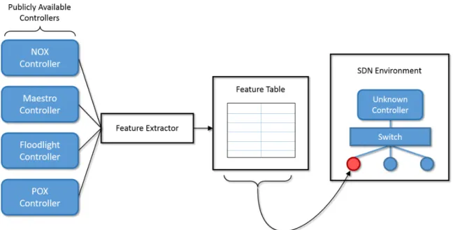
The abstract design of the fingerprinting process is shown in Figure 3.1. The
controller represents a company or entity using a controller that adheres to the OpenFlow specifications and is not in any table of features. As a client seeking to fingerprint the known controller of an SDN environment (shown as a red circle), the client downloads a copy of the publicly available SDN controller and adds the SDN controller’s features to the table of features through feature extraction. Next, the client observes the features of the unknown SDN controller and determines whether they match a set of features in the table.
Figure 3.1: SDN Controller Fingerprinting Process
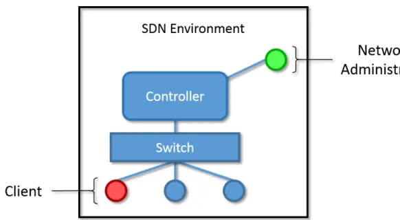
With access to a new SDN controller, an administrator can extract any and all features by examining the source code (provided the SDN controller’s source code is available), reverse engineering the SDN controller, or using the SDN controller in a network environment and discovering features. It is important to note that the set of features observable by the client is limited compared to the set of features extractable by an administrator of that SDN controller. Emphasis is placed on the fact that administrators can
extract features, while clients can observe features. A network administrator, as depicted in Figure 3.2, has complete control over the SDN controller, while the client can only communicate with the SDN controller through the provided network interface. The client’s limited visibility of the SDN controller provides a requirement that must be fulfilled by each feature extracted into the table: each feature must be observable by a client connected to the network. If a feature inserted into the table is not observable by a client, then that feature cannot be used by the client to uniquely identify the SDN controller.
Figure 3.2: Client versus Administrator SDN Controller Visibility
During the feature extraction process, a client assumes the role of an administrator by downloading a copy of publicly available SDN controllers. By assuming the role of an administrator, the client is able to extract any feature and populate the feature table. After extracting the features of a new SDN controller, the client can then use the feature table while connected to an SDN environment and test whether the observed features of the environment’s controller match the previously extracted features.
3.3.2 Features.
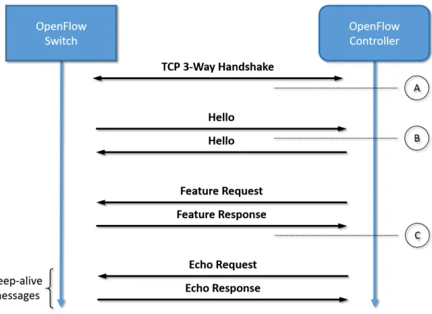
The choice of features is based on the principle of observing the response after
any provided input. Figure 3.3 shows the OpenFlow protocol communication, and
provides locations of where features can be extracted within the protocol. The left
device in Figure 3.3 represents an OpenFlow switch, however the SDN controller does not distinguish between host and switch, so long as the device is communicating using the OpenFlow protocol. Point A represents the time just after the TCP 3-way handshake has concluded. Observing what the controller communicates immediately after point A may reveal unique messages that constitute a unique feature of the controller. An example feature at Point A is whether the controller begins sending the symmetric OpenFlow Hello packet, or if the SDN controller waits for a received OpenFlow Hello packet first. Point B represents the time just after the client sends the OpenFlow Hello packet. An example of an observable feature at point B includes the very next packet received from the SDN controller, which may be an OpenFlow Feature Request packet, adhering to the OpenFlow specification, or some other packet depending on the SDN controller implementation. The very next input provided by the client is a response to the OpenFlow Feature Request packet. Point C represents the time just after the OpenFlow Feature response is transmitted. Any future input by the client creates a new point in Figure 3.3, and thus adds a new feature to the feature table.
The list of features used for the current SDN controller fingerprint process is shown in Table 3.1. The time column represents the most recent action completed by the client, while the feature column shows the response observable from the SDN controller. A time of “any” signifies that the feature can be collected at any time during the connection between the client and controller, and does not follow any event listed in Figure 3.3. Adding a new SDN controller to the feature table may require finding new features that distinguish the
Figure 3.3: OpenFlow Protocol Feature Extraction Points
feature requires that the new feature’s value be determined for each SDN controller already in the table. If a feature is obtainable by one SDN controller, but not another, then that lack of availability of a feature serves as identifiable information that is still populated within the feature table. Section 3.4 contains experiments verifying each feature as observable from the perspective of a client connected to the SDN environment.
Table 3.1: List of Features and Collection Times
# Time Feature
1 Any Default Flow Inactivity-Timeout Period
2 Any Default Flow Hard-Timeout Period
3 After TCP Handshake Does the SDN controller transmit an OF Hello packet?
4 After TCP Handshake Does the SDN controller transmit an Echo Request?
5 After TCP Handshake Does the SDN controller transmit a Feature Request?
6 After Client Sends Hello The set of packets sent by the SDN controller
7 After Client Sends Feature Response The set of packets sent by the SDN controller
3.4 Experiments
This section provides specific details regarding each experiment conducted throughout
this thesis. Each experiment begins with the reasoning for the experiment, a list of
assumptions pertaining to the experiment, the parameters, the hypothesis, and finally the experimental design. Experiment 1 demonstrates that a client can accurately determine whether the connected network environment is a traditional environment or an SDN
environment. Experiment 2 verifies that the first feature, the SDN controller’s flow
inactivity timeout period, can be accurately determined by a client connected the SDN environment. Experiment 3 verifies that the second feature, the SDN controller’s hard timeout period, can be accurately determined as a client connected to the SDN environment. Experiment 4 shows that these features can combine to form a table of SDN controller features able to fingerprint the controller software.
3.4.1 Experiment 1: Verify SDN Environment.
The goal of Experiment 1 is to determine whether a client within a network environment can accurately determine if that network environment is an SDN environment