1
Application of Fractional
Frequency Reuse Technique for
Cancellation of Interference in
Heterogeneous Cellular Network
A THESIS SUBMITTED IN PARTIAL FULFILLMENT OF THE
REQUIREMENTS FOR THE DEGREE OF
Master of Technology
in
ELECTRONIC SYSTEMS AND
COMMUNICATION
by
CHIRANJIBI SAMAL
Department of Electrical Engineering
National Institute of Technology, Rourkela
2
Application of Fractional Frequency
Reuse Technique for Cancellation of
Interference in Heterogeneous
Cellular Network
A THESIS SUBMITTED IN PARTIAL FULFILLMENT OF THE
REQUIREMENTS FOR THE DEGREE OF
Master of Technology
in
ELECTRONIC SYSTEMS AND
COMMUNICATION
by
CHIRANJIBI SAMAL
ROLL NO: 211EE1379Under the Guidance of
PROF. SUSMITA DAS
Department of Electrical Engineering
National Institute of Technology, Rourkela
I
National Institute Of Technology
Rourkela
CERTIFICATE
This is to certify that the thesis entitled, “APPLICATIONS OF
FRACTIONAL FREQUENCY REUSE TECHNIQUE FOR
CANCELLATION OF INTERFERENCE IN HETEROGENEOUS
CELLULAR NETWORK” submitted by Mr. CHIRANJIBI SAMAL in
partial fulfillment of the requirements for the award of Master of Technology Degree in Electrical Engineering with specialization in “ELECTRONIC SYSTEMS AND COMMUNICATION” at National Institute of Technology, Rourkela (Deemed University) is carried out by him under my supervision and guidance.
Prof. Susmita Das
Department of Electrical Engineering National Institute of Technology
Rourkela
II
Declaration
I certify that
i. The work carried out in this thesis is original and has been done by myself under the guidance of my supervisor
ii. For writing the thesis, I followed the guidelines provided by the institute. iii. Whenever I used content in this thesis from another source, I have given due
credit to them by citing them in the text of the thesis and giving their details in the references
iv. The work has not been submitted to any other Institute for any degree.
Chiranjibi Samal
Dept. of Electrical Engineering
NIT Rourkela
DEPARTMENT OF ELECTRICAL ENGINEERING NATIONAL INSTITUTE OF TECHNOLOGY, ROURKELA
III
ACKNOWLEDGEMENTS
This project is by far the most significant accomplishment in my life and it would be impossible without people who supported me and believed in me.
I would like to extend my gratitude and my sincere thanks to my honorable, esteemed supervisor Prof. Susmita Das, Department of Electrical Engineering. She is not only a great lecturer with deeper vision, but also more importantly a kind person. I sincerely thank for her exemplary guidance and encouragement. Her trust and support inspired me in the most important moments of making right decisions and I am glad to work under her supervision.
I am very much thankful to our Head of the Department, Prof. Anup Kumar Panda, for providing us with best facilities in the department and his timely suggestions and all my teachers Prof. Dipti Patra, Prof. K. RatnaSubhashini, Prof. Prasanna Kumar Sahu, and Prof. Supratim Gupta for providing a solid background for my studies. They have been great sources of inspiration to me and I thank them from the bottom of my heart.
I would also give my thanks to Mr Deepak Kumar Rout and Kiran Kumar Gurrala who gave me valuable advice on the thesis direction and helped whenever I asked for his expertise.
I would like to thank all my friends and especially my classmates for all the thoughtful and mind stimulating discussions we had, which prompted us to think
beyond the obvious. I’ve enjoyed their companionship so much during my stay at
NIT, Rourkela.
Last but not least I would like to thank my beloved parents, Mr Chaitan Samal & Mrs Pramila Samal who taught me the value of hard work by their own example. They rendered me enormous support being apart during the whole tenure of my stay in NIT Rourkela.
IV
Table of Contents
LIST OF FIGURES ... VI LIST OF ABBREVIATIONS ... VII
ABSTRACT ... 1 1. INTRODUCTION... 2 1.1 OVERVIEW ... 2 1.2 MOTIVATION ... 5 1.3 LITERATURE SURVEY ... 6 1.5 THESIS ORGANIZATION ... 8
2. LTE FEMTOCELLS-AN OVERVIEW ... 11
2.1 INTRODUCTION ... 11
2.2 LONG TERM EVOLUTION (LTE) ... 12
2.3 LTE-ADVANCED (LTE-A) ... 15
2.4TYPES OF FEMTOCELLS ... 16
2.4.1 Domestic ... 16
2.4.2 Enterprise ... 16
2.4.3 Metro-femtocell ... 16
2.5 HOW FEMTOCELLS WORK? ... 16
2.6 HETEROGENEOUS NETWORKS ... 18
2.7 ACCESS CONTROL ... 19
2.8 BENEFITS AND CHALLENGES FOR FEMTOCELLS ... 19
2.8.1 Advantages for users. ... 19
2.8.2 Advantages for operators ... 20
2.8.3 The disadvantages of femtocells ... 20
3. INTERFERENCE SCENARIOS IN HETEROGENEOUS NETWORK. ... 23
3.1 INTERFERENCE CHALLENGE ... 24
3.2 INTERFERENCE MITIGATION TECHNIQUES ... 24
3.2.1 Feasible Solutions ... 26
V
3.3.1 HeNB Measurements ... 28
3.3.2 Information Exchange ... 29
3.4 INTERFERENCE COORDINATION ... 31
4. IMPROVED FFR SCHEME FOR INTERFERENCE MITIGATION ... 35
4.1 FRACTIONAL FREQUENCY REUSE ... 35
4.2 TYPES OF FFR SCHEMES ... 37
4.3 IMPLEMENTION OF THE PROPOSED SCHEME FOR FEMTOCELLS ... 37
4.3.1Analysis of ProposedScheme ... 38
4.4 MATHEMATICAL ANALYSIS ... 41
4.4.1 Calculation for SINR ... 41
4.4.2 Calculation for Throughput ... 43
4.4.3 Calculation for Outage Probability ... 44
4.4.4 Calculation for Cumulative Distribution function ... 45
4.5 STEPS FOLLOWED TO IMPLEMENT THE PROPOSED SCHEME ... 45
5. RESULTS AND DISCUSSION ... 48
5.1 NETWORK ARCHITECTURE AND FREQUENCY PLANNING MODEL. ... 48
5.2 SCENARIOS AND ENVIRONMENTS ... 49
5.2.1 Simulation study ... 49
5.3 SIMULATION RESULTS ... 51
6. CONCLUSION AND SCOPE FOR FUTURE WORK ... 60
DISSEMINATION OF WORK: ... 61
VI
LIST OF FIGURES
Figure 1.1 Structure of Femtocell 5 Figure 2.1 Types of cells 12 Figure 2.2 How femtocell work 17 Figure 2.3 Architecture of femtocell 17 Figure 2.4 Heterogeneous Networks 18 Figure 3.1 Cross tier 24 Figure 3.2 Co tier 24 Figure 3.3 Standard reuse scheme 32 Figure 4.1 Macrocell Netwrok 36 Figure 4.2 Repeated Pattern of Frequency Reuse 36 Figure 4.3 Frequency Band 39 Figure 4.4 Proposed interference management scheme using FFR 41 Figure 5.1 Frequency band 49 Figure 5.2 Throughput of macro users for center and edge 54 Figure 5.3 NoFFR 54 Figure 5.4 FFR-3 55 Figure 5.5 Proposed Scheme 55 Figure 5.6 Throughput of macro and femto users in edge 56 Figure 5.7 SINR vs CDF 57 Figure 5.8 Outage probability of macro and femto users 59
VII
LIST OF ABBREVIATIONS
3GPP 3rd Generation Partnership Project LTE Long Term Evolution
FFR Fractional Frequency Reuse FUEs femtocells users
ITU International Telecommunication Union 1G First Generation
2G Second Generation 3G Third Generations 4G Fourth Generations FBSs Femtocell Base Stations
UMTS Universal Mobile Telecommunications System E-UTRAN Evolved UMTS Terrestrial Radio Access Networks QoS Quality of Service
SCs Sub-Carriers UE User Equipment F-BS Femtocell Base Station F-UE Femtocell User Equipment F-ALOHA Frequency ALOHA
DFP Dynamic Frequency Planning LIP Least Interference Power CCI Co channel Interference IP Internet Protocol
VIII
LTE-A LTE Advanced
HetNets Heterogeneous network HeNB Home Evolved NodeB eNodeB Evolved NodeB
ICIC Intercell Interference Coordination
WiMAX Worldwide Interoperability for Microwave Access MNO Mobile Network Operators
GPS Global Positioning System MUE Macro User Equipment HUE Home User Equipment NLM Network Listen Mode
REM Radio Environment Measurement RIP Received Interference Power NLM Network Listen Mode
FFR Fractional Frequency Reuse SFR Soft Frequency Reuse
SINR Signal to the Interference and Noise Ratio CDF Cumulative Distribution Function
National Institute of Technology, Rourkela Page 1
ABSTRACT
The continuously growing number of mobile devices in terms of hardware and applications augments the necessity for higher data rates and a larger capacity in wireless communication networks. The Long Term Evolution (LTE) standard was designed to provide these mobile users with a better throughput, coverage and a lower latency.
This thesis studies a specific area in Heterogeneous Networks; the subject of femtocells. The aim of femtocells is to provide better indoor coverage so as to allow users to benefit from higher data rates while reducing the load on the macro cell. Femtocells were proposed for Long Term Evolution (LTE) for indoor coverage. It is achieved using access points by home users. However, co-channel interference is a serious issue with femtocells that may dramatically reduce the performance of femto and macrocells. The system capacity and throughput decreases. As femtocells use the same spectrum as the macrocells, and the femtocells are deployed without proper planning, interference from femtocells to macrocells becomes a major issue.
In this thesis, the interference from femtocells to macrocells is studied and a solution for the mitigation of this kind of interference is suggested using FFR mechanism. In our proposed scheme for interference avoidance, femtocells use those frequency sub bands which are currently not being used within the macrocell, the process of assigning the frequency bands is based on FFR. The simulation results suggest that the suggested technique enhances total/edge throughputs, and optimizes the SINR and CDF of femtocells users (FUEs) and reduces the outage probability of the network.
National Institute of Technology, Rourkela Page 1
Chapter 1
National Institute of Technology, Rourkela Page 2
1. INTRODUCTION
1.1
OVERVIEW
Cellular phones play a dominant part in modern day life. Nowadays it's very uncommon to see a person without access to a mobile phone. Latest facts from ITU [9] reveal that by the end of 2013 there are 6.8 billion mobile phone users and by 2014 this will exceed the world population. Since the introduction of smart phones in early 2000s the numbers of online users have grown rapidly and with that the data rates in cellular networks have increased to greater proportions. What these trends indicate is whilst network penetration is spreading to every part of the earth, mobile phone and internet is becoming more and more affordable to the commoner. With these technological advancements arises the need to increase network capacity and speed. As the number of subscriber’s increases and data rate demand rises, traditional macrocells find it difficult to make demands meet especially in densely populated places.
The cellular market has always been a demanding, ever evolving market. Since the introduction of mobile phones in the early 1990s, digital mobile phones have grown to reach around 5 billion subscriptions worldwide, around 76% of the world population [1]. In parallel, the Internet has been also growing, to reach 1.6 billion users worldwide, nearly 25% of the world population [2]. Blogs, social networks, video streaming and video gaming are continuously pushing the Internet traffic to its limits.
The current cellular systems have started evolving since the 1980s. The introduction of First Generation (1G) mobile networks aimed at providing voice only services. It was based solely on analog technologies. The 1G system has been replaced soon by
National Institute of Technology, Rourkela Page 3
Second Generation (2G) digital mobile systems. The introduction of Third Generation (3G) mobile services [3] has merged both the digital mobile technology and the Internet technology. This merging boosted markets, promoting the fact that consumers are getting too attached to their mobile phones and increasing their hours of stay online. This also expanded the market for new bandwidth demanding applications that encourage more mobile usage.
The current specifications of Fourth Generation (4G) wireless cellular standards promise hundreds of Mbit/s that should reach up to 1Gbit/s for low mobility communications. With the ever increasing number of mobile users in the same territory, these rates might be difficult to achieve without optimized signaling, modulation, coding and interference resistance mechanisms. Nowadays, an emerging trend has been put into action to virtually extend the territory covered by a certain provider, which is: layering cellular networks, resulting in the formation of small cells within larger cells, as in Figure 1.1.
Since shrinking the cell size is the simplest and most effective way of increasing wireless throughput [7, 8], hence, was the introduction of indoor base stations forming picocells and recently femtocells [10]. The introduction of these small coverage networks requires also optimized operational mechanisms in order to co-exist with larger macrocell networks. Typically, femtocells form a coverage area that layers the macrocell coverage area. The two layers share the physical space, and form smaller cells that provide indoor coverage within the vicinity of larger cells, as shown in Figure 1.1. Femtocells are expected to have a very strong penetration rate at homes, offices and malls. End users will install their Femtocell Base Stations (FBSs) on their own.
National Institute of Technology, Rourkela Page 4
Figure 1.1 Structure of Femtocell
FBSs installation will be done in a convenient plug and play manner, and hence, non-coordinated ad-hoc deployment is inevitable. Such deployment is more likely to introduce interference [11], which will adversely affect the capacity of the radio system in addition to the quality of the individual communication links.
In 2008 the Long Term Evolution (LTE) was introduced to cater these needs and with that the femtocell concept was introduced. As a result of this, in a cellular networks mixture of macro and other smaller cells, such as pico and femto cells, are expected to coexist in the future. These new cells provide the network the capability
2G
3G
4G
National Institute of Technology, Rourkela Page 5
to provide satisfactory services to places having high load, especially in densely populated areas and also to the cell edges where signal strength from macrocells can be low. But there are some adverse effects that can arise because of this coexistence. As an example, interference among different cells can occur, especially among femtocells and macrocells because femtocells use the same spectrum used by macrocells and cell planning is also not performed like in picocells. This is also called inter cell interference. The main reason for the unplanned deployment of femtocells is that they are installed by home users, not the network operator.
1.2
MOTIVATION
LTE is developed by the 3rd generation Partnership Project (3GPP) in order to make sure the effectiveness of its standards in the long term. Recently it is also known as 4th generation technology. LTE is the evolution of 3rd generation mobile technology, also called as Universal Mobile Telecommunications System (UMTS). The main challenges for LTE is to come up with new radio access technology so that high data rates, low latency can be offered. LTE is also known as E-UTRAN (Evolved UMTS Terrestrial Radio Access Networks).
For indoor coverage enlargement the LTE has grown a femtocell. Femtocells have been attracting much attention recently for indoor coverage. The femto cell accompanies differing advantages to both consumers and operators, such as improved system capacity, increased indoor coverage, made smaller capital, operation expense and Quality of Service (QoS). The femtocell could be a drawing attention solution due to becoming larger data services and indoor phone calls but not enough macrocell coverage.
National Institute of Technology, Rourkela Page 6
Nevertheless, interference difficulty between the macrocell and the femtocell should be resolved .It can be noticed that some operators did not even grow positively in terms of voice revenue and that data revenue growth was more dominant.
1.3
LITERATURE
SURVEY
In [12] Jeffrey G. et al. Presents an overview of femtocells, describes their important visible features, and predicts preliminary growth in coming years, including reduction in the size of the cell and the importance of femtocell in the future.
In [13] Chandrasekhar.et al.it gives the idea about the mechanics and profession fight for femtocells and explainsthe state of the art on each front. It also explainsthe technical dispute problems for femtocell and gives initial knowledge for reducing it. Vishnupriya.P. et al. [14]. In this paper, it shows the techniques how to mitigate interference mitigation in macrocell and femtocell and it suggests how to increase the total network accomplishment using frequency reuse techniques. The throughput can be enhanced by considering inner cell radius and the frequency distribution to the macrocell together for the division of cells in the entire coverage zone..
Bouras et al. In paper [15], a frequency reuse preference from among choices, techniques is suggested; desire to decrease cross-tier CCI among femtocells and macrocells. Every macrocell is detached into outer and inner scope and the frequency is divided into FFR 1 and FFR 3 respectively.
Avani Dalal.et al. In [16] self-configuration fractional frequency reuse scheme, subset of sub-carriers (SCs) are allocated to the cell edge of femtocells and all SCs are utilized at the cell center. According to this scheme the F-BS gets the periodic report about the user equipment (UE) from F-UE. If interference level is bigger than the threshold value, then FFR is performed on the neighboring F-BS by selecting a
National Institute of Technology, Rourkela Page 7
distinct set of SCs for cell edge and also reduces the cell-center radius till the user lies at the cell-edge.
Bharucha.et al. This approach [17] manipulates the cell ID of the home evolved nodeBs (HeNBs) and also reduces the interference caused from common reference symbol, physical downlink control channel etc to trapped macro UE. This method is compliant in case of closed access femto-cells and signaling is not required. Thus, by transmitting data to femto UEs from HeNB the performance of trapped macro UEs is improved.
Zahir et al. In this paper [18] give a rundown important idea of femtocells and the bigger question come up against a situation in the bigger scale arrangement. The important question of interference management is talking over within the specific aspect with its classes in femtocells and the answers suggested to control interference has been given a rundown. It also gives the idea about the present femtocell uniformity and the expected examination management of femtocells has also been supplied.
Spectrum partitioning and Frequency ALOHA (F-ALOHA) scheme were suggested [4]. By allocating orthogonal spectrum, it takes off interference between the macrocells and the femtocells. In the femtocells, each of the femtocell uses sub-channels in a random manner. An optimum spectrum share for the femtocells can be resolved. Nevertheless, this technique is based as to an ideal channel approach. Even though the spectrum is utilized adaptively, the full bands are not serviced for the macrocell.
For interference mitigation Dynamic Frequency Planning (DFP) algorithm was also a proposal [5].After separating the OFDMA network into various sectors, for every sector the quantity of sub-channels are calculated approximately to think
National Institute of Technology, Rourkela Page 8
carefully about consumer band width demand.Interference between the sectors is evaluated when the same frequency is transmitted in the sectors.To minimize the overall network interference Optimization function is run.Nevertheless, this technique following a network structure which is centralized, therefore it is not suitable to manage femtocell for an individual owner.
FFR is the method to decrease the inter-cell interference in macrocell system, particularly for the cell edge consumers. In addition to it is beneficent to reach a goal the reuse factor of one. Under these circumstances, for the macro users the interference from the femtocells arrangement should be made smaller. So, we give more stress on the interference mitigation using FFR between the macrocell and femtocell.
1.4 OBJECTIVES
The main objectives of this thesis are: 1. Study of the various cellular structures.
2. Investigation of interference cancellation schemes in heterogeneous framework. 3. Proposing an interference management scheme to overcome the interference
between femtocell and macrocell.
4. Evaluation of SINR, throughputs and outage probability in the heterogeneous network using the modified Fractional Frequency Reuse technique.
1.5
THESIS
ORGANIZATION
The thesis is organized as follows:Chapter 1: Introduction
Chapter 1 consists of objectives, motivation behind the project work and literature survey. This chapter gives brief idea about the Femtocells.
National Institute of Technology, Rourkela Page 9
Chapter 2: LTE Femtocells-An Overview.
This chapter gives an overview of the femtocells and gives an introduction to its current standardization environment LTE and LTE Advanced which is also known as 3GPP Rel. 10.
Chapter 3: Interference Scenario in Heterogeneous Network.
This chapter gives the idea about interference and inter cell Interference Coordination (ICIC).And also how to control the interferences.
Chapter 4: Improved FFR Scheme for Interference Mitigation.
This chapter describes about Fractional Frequency Reuse, the types of Fractional Frequency Reuse and the reuse factor. And the system model and explains the Proposed Scheme. The mathematical expression for SINR for femtocell and macrocell respectively, channel gain, capacity of macro consumer, Overall throughput and outage probability are derived in this section. Also the Operational Algorithm.Chapter 5: Simulation study, Result and Discussion.
In this chapter, we present the results of our simulation. The simulation is carried out in MATLAB and shows the plots for throughput of macro consumers in the center and edge, throughput of the macro and the femto consumers only in edge region, SINR CDF of FUEs and Outage probability of macro and femto consumers.
Chapter 6: Conclusion and Scope of Future Work
The final chapter presents the conclusions and also gives a brief description on how this work can be extended for further enhancements.
National Institute of Technology, Rourkela Page 10
Chapter 2
LTE FEMTOCELLS-AN
National Institute of Technology, Rourkela Page 11
2. LTE FEMTOCELLS-AN OVERVIEW
2.1
INTRODUCTION
Femtocells are small, low power, low cost, short ranged and plug and play cellular base stations that can be placed in homes and can be directly connected to the backhaul network through Internet Protocol (IP). By means of a network connection such as Asymmetric Digital Subscriber Line (ADSL) or through optical fiber this backhaul connection can be established. From the user's point of view, these are plug and play devices and no prior technical knowledge about the installation is required. However, these devices have to be purchased from the mobile network operator by anyone wishing to have it in their residences. The advantages of having a femtocell are that the indoor coverage can be enhanced, coverage holes can be eliminated and also the operators can provide a better service at the cell edge. A detailed description about the advantages and disadvantages of having a femtocell are given in the section 2.6. Femtocells are also called Femto base stations and it's a subset of a larger group called small cells.
Other types of base stations defined by 3GPP are “Macro base stations” for wide area coverage, medium range base stations called “Micro base stations” and local area base stations called “Pico base stations” for the coverage of large buildings like
shopping malls and supermarkets. Figure 2.1 illustrates an overview of different types of cell with their size and capacity. But the main advantage of femtocells over picocells is their affordability for domestic use like Wi-Fi hotspots. There are currently three organizations working on the standardization of the femtocells, 3GPP, Small cell Forum and Broadband Forum. The industry and the universities are
National Institute of Technology, Rourkela Page 12
also cooperating with them in the standardization process. As this thesis is based on the3GPP Rel. 10 standardization for femtocells, which is also called LTE Advanced (LTE-A), in the following section a brief introduction on LTE-A and its new features is given.
Figure 2.1 Types of cells
2.2
LONG
TERM
EVOLUTION
(LTE)
LTE – Long Term Evolution is a technology standard for high-speed wireless communications through cellular networks. Large telecommunication companies around the world have integrated LTE into their networks by installing and
National Institute of Technology, Rourkela Page 13
upgrading equipment on cell towers and in data centers. Devices with LTE support began appearing in 2010. Higher-end Smartphones starting with Apple iPhone 5 feature LTE support, as do many tablets with cellular network interfaces. Newer travel routers have also added LTE capability. PCs and other laptop or desktop computers generally do not offer LTE.
Customers using an LTE network experience greatly varying connection speeds depending on their provider and current network traffic conditions. Benchmark studies show LTE in the U.S. typically supports downloads (downlink) data rates between 5 and 50 Mbps with uplink (upload) rates between 1 and 20 Mbps. (The theoretical maximum data rate for standard LTE is 300 Mbps.) Technology called LTE-Advanced improves on standard LTE by adding new wireless
transmission capabilities. LTE-Advanced supports a theoretical maximum data rate more than three times that of standard LTE, up to 1 Gbps, allowing customers to enjoy downloads at 100 Mbps or better. The networking industry recognizes LTE a 4G technology along with WiMax and HSPA. None of these
qualified as 4G based on the original definition of the International Telecommunications Union (ITU) standards group, but in December, 2010 the ITU re-defined 4G to include them. While some marketing professionals and press have labelled LTE-Advanced as 5G, no widely-approved definition of 5G
exists to justify the claim.
LTE is broadly deployed in urban areas of North America and Europe. Many parts of Africa and some countries in South America lack LTE or similar high-speed wireless communication infrastructure. China has also been relatively slow to adopt LTE compared to other industrialized nations. Those living or traveling in rural areas is unlikely to find LTE service. Even in more populated areas, LTE
National Institute of Technology, Rourkela Page 14
connectivity can prove unreliable when roaming, due to local gaps in service coverage. LTE communications work over Internet Protocol (IP) with no provision for analog data such as voice. Service providers normally configure their phones to switch between a different communication protocol for phone calls and LTE for data transfers.
However, several voices over IP (VoIP) technologies have been designed to extend LTE to support simultaneous voice and data traffic. Providers are expected to gradually phase these VoIP solutions their LTE networks in the coming years. Many customers have reported reduced battery life when enabling the LTE functions of their device. Battery drain can happen when a device receives a relatively weak LTE signal from the cell towers, effectively making the device work harder to maintain a stable connection. Battery life also decreases if a device maintains more than one wireless connection and switches between them, which can happen if a customer is roaming and changing from LTE to 3G service and back frequently. These battery life complications are not limited to LTE, but LTE can exacerbate them as the availability of service can be more limited than other types of cell communication. Battery issues should become a non-factor as the availability and reliability of LTE improves. LTE routers contain a built-in LTE broadband modem and enable local Wi-Fi and/or Ethernet devices to share the LTE connection. Note that LTE routers do not actually create a local LTE communications network within the home or local area. Similar security considerations apply to LTE as other IP networks. While no IP network is truly secure, LTE incorporates various network security features designed to protect data traffic.
National Institute of Technology, Rourkela Page 15
LTE and Wi-Fi serve different purposes. Wi-Fi works best for servicing wireless local area networks while LTE works well for long-distance communications and roaming.
A person must first acquire an LTE client device and then sign up for service with an available provider. Especially outside the United States, only one provider may service some locales. Via a restriction called locking, some
devices, primarily Smartphones, only work with one carrier even if others exist in that region. The best LTE networks offer a combination of wide coverage, high reliability, high performance, affordable prices and great customer service. Naturally no one service provider excels in every aspect. Some, like AT&T in the U.S., claim higher speed while others like Verizon tout their wider availability.
2.3
LTE-ADVANCED
(LTE-A)
As mentioned in section 1.1 femtocells were first standardized in 2009 by the 3GPP. The initial standard formed parts of 3GPP's Release 8 and was interdependent with Broadband Forum continuation to its Technical Report-069 (TR-069) [22]. It was further enhanced by the introduction of heterogeneous networks for the co-channel deployment of macrocells and small cells in 3GPP Release 10. Instead of providing any enhancements to the macro base stations, the focus of LTE-A has been to come up with new technologies and features for LTE in order to provide several benefits for the users and the operators in terms of increased throughput, capacity and coverage.
National Institute of Technology, Rourkela Page 16
2.4TYPES
OF
FEMTOCELLS
There are three types of femtocells; Domestic, Enterprise and Metro-femtocell.
2.4.1 Domestic
It is typically a four channel Unit; it is capable of handling four voice calls and others many more attached to it to standby. It is basically used in the home.
2.4.2 Enterprise
It is typically a larger device capable of handling between 8 and 32 channels in the very heavily populated environment. it is basically used in the office.
2.4.3 Metro-femtocell
It is a new concept where the operator himself micro lies large number of femtocells to saturate particularly high traffic areas. This is particularly used at 4G and LTE technology.
2.5
HOW
FEMTOCELLS
WORK?
If your cell phone is ringing and you answer it.
If the phone is in close proximity to your home femtocell it will automatically route its voice transmission through the femtocell rather than through the nearest cell phone tower. Essentially, the femtocell is low-output cell tower that can rout voice data over short distances.
The femtocell sends the voice data through your home cable or DSL modem, thus letting you save money on phone calls in your house by enabling you to send them over IP. As shown in the figure 2.2.
National Institute of Technology, Rourkela Page 17
Figure 2.2 how femtocells work
Fundamentally, they look for mobile phones as though they are normal mobile phone base station.
They communicate in the same way, in same frequency using the same signal protocols and the same techniques.
The mobile signal them self is when converted and sent by your broadband internet connection through to the Femto gateway. These connect to some hundred or thousand femtocell and convert the traffic into the same format this provided through a radio network controller for an outdoor cell site. It described in the figure 2.3.
National Institute of Technology, Rourkela Page 18
2.6
HETEROGENEOUS
NETWORKS
A Heterogeneous network (HetNets) refers to the co-channel deployment of macrocells and small cells with the purpose of increasing the network capacity and coverage and also to remove coverage holes in indoor and outdoor areas. Small cells here mainly refer to picocells, femtocells, distributed antennas and relays. Picocells are well suited for shopping malls and large office buildings and they enhance the coverage in such places. Distributed antennas provide a uniform quality of service over the total coverage area, although they don't increase the capacity. They just share the same resources in the air interface in a large coverage area. The advantage of having distributed antennas is that the system can be upgraded easily by plugging in a new base station and distributed antennas simply extend the base station's antenna ports. The main advantage of femtocells over picocells and distributed antennas is that they do not need to be carefully planned. One of the most important aspects of heterogeneous networks is cross-layer interference which is more relevant to femtocells. Figure 2.4 illustrates an overview of a heterogeneous network comprising of all the above mentioned technologies.
National Institute of Technology, Rourkela Page 19
2.7
ACCESS
CONTROL
Open Access
It provides the service to anyone who passes nearer to the femto.
Closed access
A particular fixed number of home users are licensed to use the femto.
2.8
BENEFITS
AND
CHALLENGES
FOR
FEMTOCELLS
The femtocell concept provides advantages for both users and operators. But as any other newly introduced technology, it still has some issues that requires more research. Sections 2.8.1, 2.8.2 and 2.8.3 provide descriptions of the advantages and challenges of femtocells.
2.8.1 Advantages for users.
Better indoor coverage: Wall penetration loss is a reason for the weakening of the signal which arrives from macrocells at indoors. Hence femtocells are a good low cost option. This is especially advantageous for the cell edge users as they receive further weakened signals from the macro cells due to path loss. Furthermore, interference from other macro eNodeBsare also high at the cell edge. If a HeNB is deployed in such a place with a reasonable transmit power a much better indoor coverage can be achieved.
National Institute of Technology, Rourkela Page 20
Lower transmission power at home: Both phone and the base station are now indoors, so they don't need to transmit with higher transmit powers. This is also beneficial for the health aspects of the users.
Increased phone battery life: Since the HeNB receiver is at indoors, the UEs do not need to transmit at higher powers to achieve a better reception quality. Hence this increases phone's battery life.
Since femtocells are plug and play devices, no technical knowledge is required by the users for installation and operation.
2.8.2 Advantages for operators
Higher data rates: The users subscribed to the Mobile Network Operators (MNO) receive higher data rates from femtocells depending on their broadband connection through Local IP Access. The user traffic goes to the Internet Service Provider instead to the mobile operator network. Hence the MNO is able to provide better data rates for the users while offloading traffic from the macrocells.
Increased Network capacity: Traffic offload from macrocells provides better network capacity and it also contributes for a slower growth of the backhaul costs.
Increased Revenue: MNOs can place special tariffs for calls taken through femtocells. This also depends on the pricing policy of the operator.
2.8.3 The disadvantages of femtocells
Interference: This is the main problem of using femtocells is that they interfere with the nearby macro users as well as other femtocell users if it's
National Institute of Technology, Rourkela Page 21
under co-channel deployment. More about this will be elaborated in chapter 3 because mitigating this interference is the main focus of this thesis
Quality of service: If the femtocell shares the home backhaul connection for data traffic with other equipment such as internet browsing and gaming consoles, this might affect the quality of service that it provides to the femto users. For example, if someone uses a video streaming application over the phone, the femtocell might struggle to reach the data rate requirement in a shared connection. Minimum requirements of the backhaul capacity must be expressed by the operator when the femto cells are bought. Some QoS differentiations as well as link reservation for femto traffic can be applied at the subscriber backhaul equipment.
Spectrum accuracy: Femtocells are low cost devices. It is very difficult to generate a very accurate spectrum through low cost oscillators inside these devices. Hence 3GPP has also relaxed its standards for spectrum accuracy for femtocells from its later standards starting from Release 8
Equipment location: Base stations usually find their location from the Global
Positioning System (GPS). GPS most of the time is unable to find locations indoors due to low signal quality that occurs because of high wall penetration losses.
National Institute of Technology, Rourkela Page 22
Chapter 3
INTERFERENCE
SCENARIOS IN
HETEROGENEOUS
NETWORK
National Institute of Technology, Rourkela Page 23
3. INTERFERENCE SCENARIOS IN
HETEROGENEOUS NETWORK.
There are several interference scenarios involving HeNBs, Macro eNBs, MUEs and HUEs. When an eNodeB is interfering with a UE that is attached to another eNodeB in the downlink, it’s called downlink interference and when a UE is interfering with an eNodeB's reception from another UE this is called uplink interference. When a HeNB interfere the users attached to another HeNB, this type of interference is called downlink co-layer interference. When a HeNB is interfering, the users attached to an eNodeB or vice versa, this is called downlink cross-layer interference. Figures 3.1 and 3.2 depict two scenarios of downlink co-layer and cross-layer interference respectively. Basically, there is two types of interference, these are Cross-tier and Co-tier interference.
Cross-tier
Femto-Macro interference
Interference between femtocells and Macro cells, working on the same frequency may interfere with each other.
Co-tier:
Femto-Femto Interference
Interference between neighboring femtocells may cause interference. UE transmitted signal reaching more than one femtocell.
The scenario of downlink cross-layer interference to MUEs discussed in this thesis is a result of several reasons. The first reason is that HeNBs are placed inside the coverage area of eNodeBs. The next reason is that both eNodeBs and HeNBs operate on the same frequencies which are also called co-channel deployment. Another cause is that, not only the HeNB provides coverage inside a house, but there is also a leakage of radiation to the outside which eventually results in interference.
National Institute of Technology, Rourkela Page 24
Figure 3.1 Cross-Tier Figure 3.2 Co-tier
This leakage becomes severe if the walls have more open spaces or glass windows. Another reason for interference is that the HeNBs are more often configured in CSGs. This makes handover of a MUE to a HeNB impossible even if it gets the stronger signal from the HeNB.
3.1
INTERFERENCE
CHALLENGE
Generally, the main problem of occurring interference due to two or many devices transmits nearer to each other. As is well known, the wireless network faces many interference problems. These are Inter Symbol Interference (ISI), which is happening when due to the delayed in multipath signal a symbol overlaps with the following symbols. Co Channel Interference (CCI) it occurs when a mobile transmits the data in the same channel which is already used in the nearby mobile. Co-tier and cross-tier interference which are already discuss in the above.
3.2
INTERFERENCE
MITIGATION
TECHNIQUES
Innovative interference mitigation techniques should be used with this novel type of sophisticated networks. Proposals to mitigate interference should take into consideration the nature of femtocells for a number of reasons:
National Institute of Technology, Rourkela Page 25
2. FBSs are installed and maintained by end users.
3. FBSs have limited computation and signalling power compared to regular outdoor BSs.
4. Femtocells are in most cases overlaid on macrocells.
Using these facts, we can derive a number of parameters that should be considered while designing femtocell interference mitigation solutions to ensure applicability:
Complexity requirements
Unlike the regular MBSs, the initial objective of a FBS is to provide better indoor voice and data services in a simple and cost effective way. This results in a small size FBS with limited computation and processing power. However, deployment issues necessitate avoiding complex algorithms for the mitigation purposes. By surveying the literature, we speculate that optimized algorithms based on Computational Intelligence (CI) like Genetic Algorithms (GAs), Simulated Annealing (SA), Neural Networks (NNs) and Game Theoritic-based algorithms will gain momentum in the context of research to provide stronger solutions.
Distributed Operation
In order to minimize decision delay, it is important that localized decisions are made, foregoing centralized processing, and the delays required for the two-way signalling.
Adaptability
Distributive is often linked to adaptability. Interference mitigation algorithms are expected to be highly adaptable to the surrounding environment since new FBSs can be deployed anywhere at any time, which will keep the current network infrastructure topology in a state of continuous change compared to the ordinary cellular network.
National Institute of Technology, Rourkela Page 26
Scalability
The projected density of deployment for femtocells also necessitates scalable solutions. To appreciate the minimal scale of deployment, the installation of a FBS per household should be assumed. This projected enormous volume entails highly scalable solutions.
One important aspect that should be also regarded is self-organization [34, 35]. The aforementioned zero-touch feature [24] mandates that a FBS be able to do self-configuration, self-optimization, and self-healing [9, 18]. The self-configuration characteristic mandates that a device, once powered up, starts collecting its configuration parameter and does configuration tasks, whether these parameters are hard-coded, on-chip, or reside on some server. On the other hand, self-optimization ensures that the device is always in a state of optimizing parameters such as signalling, power and frequency allocation to guarantee calm and effective communication. Finally, self-healing states that if certain communication failure occurs or degrading happens, the device should find fixes and apply them to continue operation. Self-organization is composed of all three, and is needed to ensure that the FBS unit can function on its own. Self-organization has been proposed at different phases of femtocell standardization. It can also be linked to adaptability because a FBS is in a continuous state of operation optimization. Signalling, power level and computations are examples of what can be optimized whilst the operation of a FBS.
3.2.1 Feasible Solutions
National Institute of Technology, Rourkela Page 27
The operator managed vs FBS vendor managed. An operator managed solution affirms that the cellular provider coordinates the work of different femtocells and supplies them with parameters for operating interference mitigation solutions; whereas a FBS vendor managed (on-chip) solution requires that FBSs ship Pre-configured with certain interference mitigation out-of-the-box mechanisms regardless of the network they will be deployed as part of.
Locality
A localized solution runs at each femtocell, without the need for central coordination of calculations between FBSs. Localized techniques are more preferable to support scalability which requires that a FBS works on its own or in rare cases communicates with the surrounding FBSs. Conversely, network-wide techniques provide acceptable operation with generally less sophistication because they depend on specific central entities that aggregate information from groups of femtocells and use this information to compute solutions. Local versus network-wide solutions are also referred to as decentralized versus centralized solutions.
Application level
Categorization per application level describes the level of granularity at which the solution is applied, i.e., at the tier level or at the cell level. Solutions deployed at the coarse grained tier level tend to use durable, less or no changing parameters. In contrast, fine grained cell level solutions work on a much lower level and they need to be more adaptable and highly configurable. An example to show the difference between tier level and cell level is frequency planning in opposition to frequency allocation. In a multi-tier environment portions of the spectrum are split among tiers, without going deeper into the cells; this is a tier-level technique. On the other hand,
National Institute of Technology, Rourkela Page 28
frequency allocation, where users within a cell are admitted frequency slots for transmission, is considered a cell-level technique.
3.3
INTERCELL
INTERFERENCE
COORDINATION
ICIC is the name used for the methods that are used to control interference in heterogeneous networks. Interference control is performed in both uplink and downlink. But here the priority is given to downlink interference control as the focus is on mitigating interference from HeNB to macro eNodeB user equipment. Interference control in the downlink can be basically achieved by two methods, power control and radio resource management. Downlink interference control methods can further be divided as control channel protection and data channel protection methods. The intention of this work is on data channel interference control methods.
Before activate any interference mitigating technique a HeNB first need to identify whether a user is interfered by its transmissions. For that purpose there are several types of measurements that can be collected. The following section gives some details about those measurement techniques.
3.3.1 HeNB Measurements
There are several measurements gathered by HeNBs which are important for the control of their interference and to maintain coverage. Some measurements are collected by the UEs that are attached to the HeNBs. Some measurement collections are performed by the downlink receiver of the HeNB. This is also called Network Listen Mode (NLM) of the HeNB. Other measurements are collected by the HeNB uplink receiver and this mode of measurement collection is called Radio Environment Measurement (REM) or HeNB sniffer.
National Institute of Technology, Rourkela Page 29
Received Interference Power (RIP) when they are being configured or during normal operation. This measurement is useful for interference mitigation by the HeNB. If the RIP is above a certain predetermined level, this indicates that there's a MUE nearby and the HeNB must lower its power to avoid interference in the downlink.
3.3.2 Information Exchange
Other than the above mentioned measurements, HeNBs also gather information on interference control through information exchange with eNodeBs and other HeNBs. This option has the benefit of obtaining details about the uplink and downlink conditions in nearby eNodeBs and HeNBs when the HeNB configures its power and frequency resources. There are several ways to perform this information exchange with other eNodeBs.
Over the air information from eNB to HeNB
This scenario involves the transfer of vital data among eNodeB and HeNBs directly through the air interface. The advantage over direct information exchange is that it has a low latency. Direct information exchange among eNodeBs and HeNBs can also be used to coordinate scheduling as well. This helps in reducing interference to the UEs. But the main disadvantage is that over the air broadcasting can't be used when the eNodeB needs to send different types of data to different HeNBs. The eNodeB may also not be visible to HeNBs due to fading. This may result in occasional interference to the nearby macro users. When the information is read from the air interface downlink transmission is also halted which may affect the data rate of the user.
Over the air information from (H)eNB to HeNB via UE
In this method information is exchanged among HeNBs through UEs. This also has the advantage of low latency and can also be used to reduce
National Institute of Technology, Rourkela Page 30
interference by sending scheduling information. This has the added advantage of being able to send different types of information to different HeNBs. But for proper operation there should be better links among HeNBs and UEs.
X2 based interface between eNB and HeNB, and between HeNBs
The X2 interface that exists among eNodeBs and HeNBs can also be used to transfer control information regarding interference management. This method is used currently for the exchange of such information among macro eNodeBs. But for interference control among eNodeBs and HeNBs, this might not be suitable because this link is having a high latency. The other reason is that the macro eNodeB has to send many messages to a larger number of HeNBs in its coverage area unlike in the macro-macro information exchange scenario. But information sent through this link can be accurate than information exchanged over the air interface because information exchanged over the air interface can have more packet drops due to fading. X2 being a wired link this problem does not occur. Hence, to reduce the complexity the procedures over the X2 interface can be limited to only sending Overload Indicator, High Interference Indicator and Relative Narrowband Transmit Power signals which require a higher latency among the eNodeB and HeNBs.
S1 based interface between eNB and HeNB, and between HeNBs
S1 interface exists between the E-UTRAN and the EPC or in other words, between the eNodeBs or HeNBs and the operator core network. This interface can also be used to exchange messages about interference management among eNodeBs and HeNBs. This also provides a higher
National Institute of Technology, Rourkela Page 31
accuracy of data than the air interface similar to the X2 interface. Interference mitigation schemes that are using this scheme may also face the adverse effects of high latency.
3.4
INTERFERENCE
COORDINATION
Interference coordination (also referred to as interference avoidance) is one of the most promising approaches to solve the problem of ICI in OFDMA systems, and has taken large concentration in 3GPP for LTE. The fundamental standard is to put into use few limits to the nonmaterial distribution in a relate technique between neighboring base stations. The categorization method can be classified into two types: resource management and resource scheduling, the coordination between base stations can be classified as static or adaptive.
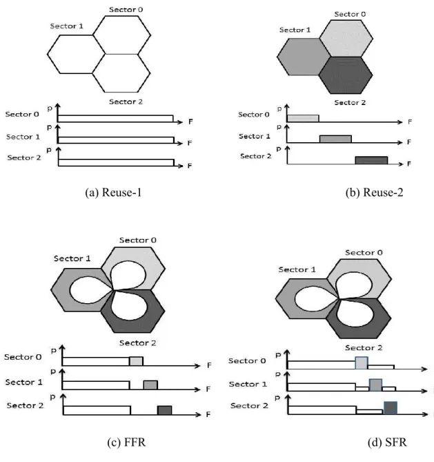
Standard reuse and reuse partitioning schemes
LTE is designed to operate with an aggressive frequency reuse plan, with reuse-1 as an objective. Figure 3.3 (a) illustrates the frequency and power allocations in the reuse-1 course of action, where every frequency resource is ready for use in all places in every sector. The below side pictures in Figure 3.3 depict the mapping of power (P) to frequency (F), showing the frequency partitions; the upper pictures
show the allocation of the frequency partitions to the sectors, including center and edge allocations in reuse partitioning schemes.
A conventional reuse scheme with a reuse factor greater than 1, such as reuse-3 or reuse-7, is the simplest interference coordination technique based on resource management. Figure 3.3 (b) illustrates the power and frequency configuration for a reuse-3 scheme. In reuse-3, each sector only gets one third of the bandwidth of the reuse-1 case, and the allocations are set up to be four-sided between right away neighboring sectors. This type of static resource management can avoid allocating
National Institute of Technology, Rourkela Page 32
the same frequency resource in the adjacent sectors, leading to substantially lower interference.
(a) Reuse-1 (b) Reuse-2
(c) FFR (d) SFR Figure 3.3 Standard reuse schemes.
Reuse partitioning is another type of resource management technique to mitigate ICI and improve sector edge performance. The essential idea is to partition the available frequency band in each sector into a reuse-1 band that is allocated to sector center users and a reuse-3 (or larger reuse) band allocated to sector edge users. Variants are possible, depending on whether the use of the edge bands of neighboring sectors is strictly prohibited in the reference sector (fractional frequency reuse (FFR), shown in
National Institute of Technology, Rourkela Page 33
Figure 3.3 (c), or made available with reduced transmission power for sector center users (soft frequency reuse (SFR), shown in Figure 3.3 (d). If a user is deemed to be an edge user; only edge band resources can be allocated. Users in the center area can access both the center band and any unoccupied edge band resources. At FFR and SFR schemes, the edge band size is a valuable sketch limit, which can be exchanged done working and perpetuation intervention (static) or adaptive to traffic load variations in neighboring sectors. Furthermore, the power levels for the center and edge band can also be adjusted to pursue an improved overall system performance. These schemes may bring in some changes to the system design and implementation, and each scheme has its own advantages and disadvantages. In the static reuse schemes and reuse partitioning schemes, the spectrum allocations in each sector remain constant over time, and can be done off-line via network planning. Therefore, no inter-base-station communication is required. However, these schemes have the disadvantage that the available bandwidth in each sector is usually much less than that of reuse-1 scheme. In particular, it is extremely low in the standard reuse schemes; for example, only one third for reuse-3 compared to reuse-1 and even lower for schemes with a larger reuse factor. For the adaptive FFR/SFR schemes, some additional information exchange will be required via inter-base-station signaling in order to agree on the edge band size, possibly on a relatively slow time scale.
National Institute of Technology, Rourkela Page 34
Chapter 4
IMPROVED FFR SCHEME
FOR INTERFERENCE
National Institute of Technology, Rourkela Page 35
4. IMPROVED FFR SCHEME FOR
INTERFERENCE MITIGATION
4.1
FRACTIONAL
FREQUENCY
REUSE
In a conventional wireless network, macrocell base stations (M-BSs) are placed next to each other in a two dimensional plane such that the whole area gets the wireless coverage. In order to provide seamless coverage across the network, the coverage area of neighboring M-BSs are overlapped. In such a network layout, inter-cell interference occurs if all the macrocells use the whole system bandwidth. To avoid this interference, frequency reuse mechanism is used.
Figure 4.1 shows a typical macrocell network using the frequency reuse scheme. No two neighboring macrocells use the same frequency band in their coverage cells. The cell in the center uses frequency bands denoted by Freq. 3 which none of its neighboring six cells use. This pattern of frequency planning is repeated through the whole network. Figure 4.2 shows the repeated pattern of frequency reuse using 3, 4 and 7 cells multiplying over a segment of the macrocell network. Although frequency planning is an excellent way to avoid inter-cell interference between neighboring macrocells, it leads to an uneconomical usage of the system bandwidth. As wireless frequency spectrum is a valuable resource, optimal utilization of the system bandwidth is of critical importance. The spectrum is becoming scarce with increasing number of wireless mobile devices. New ways to reuse the spectrum are being devised to meet the rising demand of the network bandwidth. Fractional Frequency Reuse (FFR) is a simple but useful technique to improve bandwidth usage across the network.
National Institute of Technology, Rourkela Page 36
Figure 4.1 macrocell network
National Institute of Technology, Rourkela Page 37
4.2
TYPES
OF
FFR
SCHEMES
FFR is mainly divided into two types; Hard FFR and Soft FFR [18]. In hard FFR, the participating cells use distinct set of frequencies at the cell edge area while in the cell center they use only the frequency bands not used by any of the participating cells in their cell edges.
Soft FFR also uses distinct frequency sets at the cell edges of participating cells but unlike hard FFR, the cell centers use all the remaining frequency sets. The advantage of soft FFR is that it utilizes bandwidth more efficiently than hard FFR. But, it causes more inter cell interference as compared to hard FFR.
In the initial works they used NoFFR and FFR techniques. NoFFR, in this case only a single band of frequency is there. So interference is more.
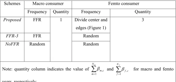
And in the FFR-3 the full frequency band is divided equally into three sub band. These sub bands are assigned to the macro and femto users’ randomly.This technique is better than NoFFR. Interference between the macro cells is decreased in this scheme. But there is Co channel interference between the femto and macro cell.which can be mitigating by our proposed scheme.In this case only three bands of frequency are used.
4.3
IMPLEMENTION
OF
THE
PROPOSED
SCHEME
FOR
FEMTOCELLS
In our proposed scheme for mitigating interference we use four frequency bands. Each cell is divided into two regions; center and edge region. We give more frequency band to the edge region femtocell. So that the interference is reduced in the edge region and the throughput is increased. So the performance is better. In this chapter we discuss about our work.
National Institute of Technology, Rourkela Page 38
4.3.1
Analysis of Proposed
Scheme
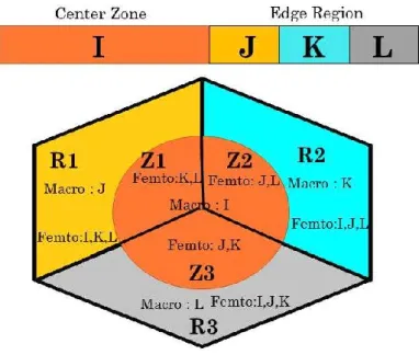
As shown in Figure 4.3 the FFR techniques are applied to each of the macrocell, for which we can easily decrease the interference among the adjacent cells and increase the throughput. Each hexagonal cell of the network is divided into two region one is inner (orange color) and the other is the outer region (colors yellow, blue and gray). The full frequency band is divided into two equal parts. The first part of this total frequency band is given to central zone with a reuse factor of one and the frequency band is denoted as I, while the rest frequency band is equally divided into three sub-bands, with a reuse factor of three and the frequency bands are denoted as J, K and L respectively. In Figure 4.3 it shows the division of the frequency band. In the outer region of a macrocell, if a femtocell is located, then we can reuse the sub band for the femto users which are used in the inner region. On the other hand, if in the inner region of the macrocell a femtocell is exist, and then the femtocell cannot reuse that sub-band which was already assigned to the users which are in cell edge of that macrocell. In each case the transmit power of the base station is the reason. The Inner cell users are always closer to the base station that means we need less transmitting power. As they always getting good coverage from the nearer base station. While for the cell edge users, we need more transmitting power from the base station. In the edge region the receiving power is less so the coverage is very bad and the interference is more. So our aim is to give good coverage to the edge region and reduce interference using FFR scheme.
National Institute of Technology, Rourkela Page 39
Figure 4.3 Frequency Band
For example, in the Figure 4.3, if in the outer zone of the central cell the femtocell is operating with the colour orange and yellow, then it cannot use not only the sub-bands Land K of colour blue and grey, respectively. Because those are given to the outer zones of the adjacent cells and also we cannot give the sub-band I with orange colour even though it is already applied in this macrocell. In these scenarios, the interference from the femtocell to the macrocell and vice versa will be mitigating. In figure 4.4 it describe the distribution of frequency sub bands for the full band into the macrocell and femtocell. The coverage of macrocell is broken in to two parts,
National Institute of Technology, Rourkela Page 40
one is center zone and the other is edge region, containing three sectors per each, In center zone it is indicated by Zl, Z2, Z3, and in the edge zone it is indicated by RI, R2, R3. The entire frequency band separates into two equal parts first part is for reuse factor 1, and the next part is again divided into 3 equal parts, all are denoted as I, J, K and L. In the center zone reuse factor 1 is used. And in the edge region reuse factor 3 is used. The sub-band I is applied to the center region (Zl, Z2, andZ3), and the sub-bands J, K and L used in the Rl, R2 andR3 regions.
Below this situation, femtocell selects those sub-bands, which are not applied in macrocell sub-area. Particularly, femtocell which is in center region has to exclude the sub band which is already used in the edge zone of that particular sector. For example, if a femtocell is in the area Rl, it can use only the sub-bands I, K, or L. and the sub band B is for the macrocell. Now in the center zone Z1 if a femtocell is located, then the sub-band K and L are used.
Due to the typical feature of OFDMA [15], macrocell is intervening by inter-cell, and by the FFR that interference is mitigated. Femto cell applies the dissimilar sub-band to prevent interference from macrocell. The Sub-sub-band is reused in the coverage of macrocell as much as possible. As femtocell have very less transmitting power. For that reason, the interference among macrocell and femtocell is considerably prevented. In order to increase the throughput of the consumers which are in the edge region, we allocated more number of sub carrier to the femtocells in that region. In our scheme we provided two sub bands to the femto users which are in the center region. And three sub bands to the femtocells which are in the edge region.
That’s why our performance is better than NoFFR and FFR-3.
This same technique is also applied in the other two sectors. Likewise we divide all the cells in same manner one is center zone and the other is edge zone. In every cell
National Institute of Technology, Rourkela Page 41
the performance is good. So the overall network performance is increases we get good coverage in the all the place. The indoor coverage is increases and the interference is decreases.
Figure 4.4 Proposed interference management scheme using FFR
4.4
MATHEMATICAL
ANALYSIS
4.4.1 Calculation for SINR
We formulate system throughput and downlink signal to the Interference and Noise Ratio (SINR). The total network is divided into 19 numbers of macrocells, and the femtocells are randomly assigned. There is interference between the macro users with the neighboring 18 macrocells and also with the adjacent femtocells.