Md. Tarikul Islam
VOICE COMMUNICATION IN MOBILE DELAY-TOLERANT NET-WORKS
Thesis submitted for examination for the degree of Master of Science in Technology
Espoo November 26, 2009
Thesis supervisor:
Prof. J¨org Ott
Thesis instructor:
Author: Md. Tarikul Islam
Title: Voice Communication in Mobile Delay-Tolerant Networks
Date: November 26, 2009 Language: English Number of pages: 9+83 Faculty: Faculty of Electronics, Communications and Automation
Professorship: Networking Technology Code: S-38 Supervisor: Prof. J¨org Ott
Instructor: Prof. J¨org Ott
Push-to-talk (PTT) is one class of voice communication system generally employed in cellular phone services. Today’s PTT services mainly rely on infras-tructure and require stable end-to-end path for successful communication. But users with PTT enabled mobile devices may travel in challenged environments where infrastructure is not available or end-to-end path is highly unreliable. In such cases those PTT services may exhibit poor performance or may even fail completely. Even though some existing PTT solutions allow users to communicate in an ad-hoc fashion, they need sufficient node density to establish end-to-end path and eventually fail to communicate in sparse mobile ad-hoc environments. Delay-Tolerant Networking (DTN) is an emerging research area that addresses the communication requirements specific to challenged networks.
In this thesis we develop a voice communication system (DT-Talkie) which enables both individual and group users to communicate over infrastructure-less and challenged networks in the walkie-talkie fashion. The DTN concept of asynchronous message forwarding is applied to the DT-Talkie in order to transmit voice messages reliably. We employ variable-length fragmentation mechanism in the application layer with the vision to speed-up session interactivity in stable scenarios. Some approaches to resolve codec interoperability issues are implied in this thesis.
To validate the concepts of the DT-Talkie, we implement an application for Maemo based Nokia Internet Tablets, leveraging the DTN reference implementation de-veloped in the DTN Research Group. Moreover in this thesis we evaluate the performance of the DT-Talkie through conducting a set of simulations using sev-eral DTN routing protocols and using different mobility models.
Acknowledgments
This thesis has been accomplished in the Department of Communications and Net-working of Helsinki University of Technology as a part of a CHIANTI project funded under Seventh Framework Programme of European Union.
I would like to express my heartiest gratitude to my supervisor, Professor J¨org Ott, for giving me opportunity to work on such an interesting topic. I am indebted for his constant assistance, encouragement, guidance and tremendous support throughout the thesis process.
I want to give special thanks to one of my colleague, Teemu K¨arkk¨ainen, who men-tored me in every stage of my thesis through solving various issues and giving valu-able comments.
Thanks also goes to my other colleagues, especially Sathyanarayan Suryanarayanan and Shengye Lu, who provided constructive suggestions on my thesis and inspired me all the time.
Finally, I would like to express deep gratefulness to my beloved parents for their fruitful advice and mental support during my studies.
Otaniemi, November 26, 2009
Contents
Abstract ii Acknowledgments iii Contents iv List of Acronyms ix 1 Introduction 1 1.1 Related Works . . . 2 1.2 Motivation . . . 3 1.3 Objective . . . 4 1.4 Thesis Outline . . . 5 2 Technology Background 6 2.1 Why DTN? . . . 6 2.2 DTN Architectural Overview . . . 72.2.1 Store-and-Forward Message Switching . . . 7
2.2.2 Endpoint Identifier (EID) and Registration . . . 8
2.2.3 Late Binding and Class of Service . . . 9
2.2.4 Fragmentation and Reassembly . . . 9
2.2.5 Contacts . . . 10
2.2.6 Time . . . 11
2.2.7 Custody Transfer . . . 11
2.2.8 Security . . . 12
2.3 Bundle Protocol . . . 12
2.3.1 Basic Bundle Structure . . . 14
2.3.2 Convergence Layer Protocols . . . 16
2.4.1 Routing in Deterministic DTNs . . . 18
2.4.2 Routing in Stochastic DTNs . . . 19
2.5 OMA specified PoC . . . 21
2.6 Summary . . . 23
3 System Architecture 25 3.1 System Concepts of the DT-Talkie . . . 25
3.1.1 Audio Encoding . . . 27
3.1.2 Application Layer Framing . . . 27
3.1.3 Bundle Addressing . . . 29
3.1.4 Bundle Routing and Delivery . . . 30
3.1.5 Group Communication . . . 31
3.2 Voice Message Fragmentation . . . 31
3.2.1 Different Fragmentation Schemes . . . 32
3.2.2 MIME Encapsulation of a Fragment . . . 33
3.3 Codec Interoperability Issues . . . 34
3.4 Summary . . . 36 4 Implementation 38 4.1 Background . . . 38 4.1.1 Maemo . . . 38 4.1.2 GTK+ . . . 40 4.1.3 GStreamer . . . 40 4.1.4 DTN2 . . . 41 4.1.5 Other Libraries . . . 42
4.2 DT-Talkie Application Architecture and its components . . . 42
4.2.1 State flow of the DT-Talkie application . . . 43
4.2.2 Bundle S/R . . . 45
4.2.4 MIME C/P . . . 48 4.2.5 GUI . . . 50 4.3 DT-Talkie Fragmentation . . . 51 4.4 DT-Talkie Screenshot . . . 52 4.5 Summary . . . 53 5 Performance Evaluation 55 5.1 Simulation Tool - ONE . . . 55
5.2 Mobility Models . . . 56
5.2.1 Random Waypoint Model . . . 56
5.2.2 Working Day Movement Model . . . 56
5.3 Simulation Setup . . . 57
5.3.1 Message Generation for ONE . . . 57
5.3.2 Destination Node Selection . . . 57
5.3.3 Routing Protocols . . . 58 5.3.4 Performance Metrics . . . 59 5.3.5 Simulation Parameters . . . 60 5.4 Simulation Observations . . . 62 5.4.1 Simulations Group 1 . . . 62 5.4.2 Simulations Group 2 . . . 64 5.4.3 Simulations Group 3 . . . 67 5.4.4 Simulations Group 4 . . . 69 5.5 Summary . . . 73 6 Conclusion 75
List of Figures
2.1 DTN protocol hierarchy . . . 14
2.2 A bundle node classification . . . 14
2.3 Classification of routing approaches in DTNs . . . 18
2.4 OMA specified PoC architecture . . . 22
3.1 General processing steps of the DT-Talkie . . . 26
3.2 Sample MIME message generated in a DT-Talkie session . . . 29
3.3 Signal representation of a voice message . . . 33
3.4 MIME encapsulation of a voice message fragment . . . 34
3.5 MIME encapsulation of three audio parts representing the same voice message . . . 36
3.6 MIME encapsulation of uncompressed audio and XML content . . . . 37
4.1 High-level architecture of the DT-Talkie application . . . 43
4.2 DT-Talkie application state flow diagram . . . 44
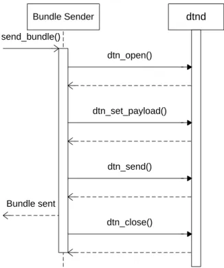
4.3 Sequence diagram of bundle sending functionality . . . 45
4.4 Sequence diagram of bundle receiving functionality . . . 47
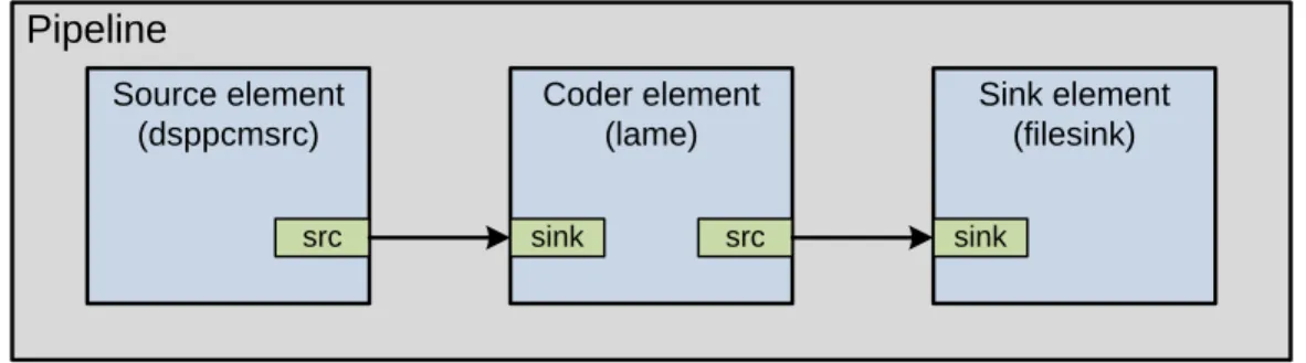
4.5 Voice recorder pipeline . . . 48
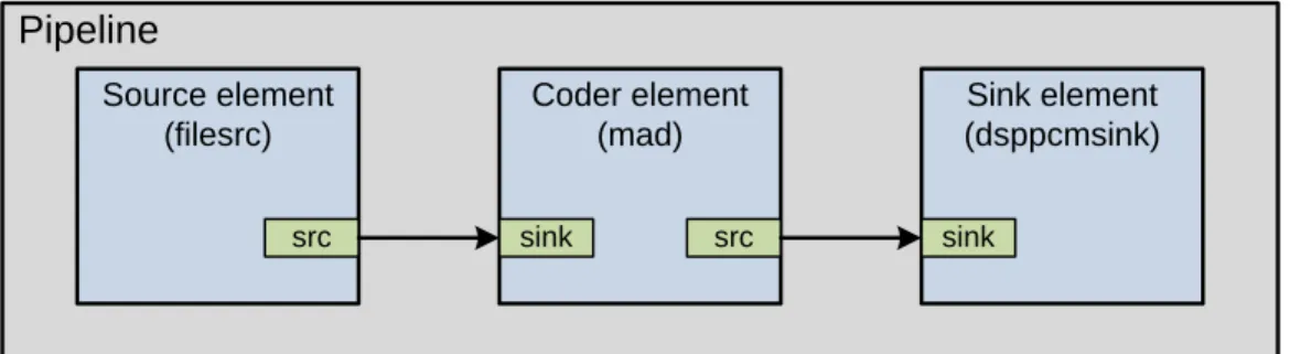
4.6 Voice player pipeline . . . 49
4.7 Fragments creation through separating talk-spurts . . . 52
4.8 Screenshot of the DT-Talkie application . . . 53
5.1 Selection of a destination node when communication radius is speci-fied corresponding to a particular source node . . . 58
5.2 A voice session with three interactions . . . 60
5.3 Message delivery probability (message mode, maximum 10 hop-count) 63 5.4 Fragment delivery probability (fragmentation mode, maximum 10 hop-count) . . . 63
5.5 Message delivery probability with loss of≤1 fragment (fragmentation mode, maximum 10 hop-count) . . . 64
5.6 Average message delivery delay (message mode, maximum 10 hop-count) . . . 64 5.7 Average fragment delivery delay (fragmentation mode, maximum 10
hop-count) . . . 65 5.8 Message delivery probability (message mode, maximum 120 minutes
TTL) . . . 65 5.9 Fragment delivery probability (fragmentation mode, maximum 120
minutes TTL) . . . 66 5.10 Message delivery probability with loss of≤1 fragment (fragmentation
mode, maximum 120 minutes TTL) . . . 66 5.11 Average message delivery delay (message mode, maximum 120
min-utes TTL) . . . 67 5.12 Average fragment delivery delay (fragmentation mode, maximum 120
minutes TTL) . . . 67 5.13 Message delivery probability (message mode, maximum 120 minutes
TTL, maximum 10 hop-count) . . . 68 5.14 Fragment delivery probability (fragmentation mode, maximum 120
minutes TTL, maximum 10 hop-count) . . . 69 5.15 Message delivery probability with loss of≤1 fragment (fragmentation
mode, maximum 120 minutes TTL, maximum 10 hop-count) . . . 69 5.16 Average message delivery delay (message mode, maximum 120
min-utes TTL, maximum 10 hop-count) . . . 70 5.17 Average fragment delivery delay (fragmentation mode, maximum 120
minutes TTL, maximum 10 hop-count) . . . 70 5.18 Message delivery probability (50 meters communication radius,
max-imum 120 minutes TTL, maxmax-imum 10 hop-count) . . . 71 5.19 Session completion rate (50 meters communication radius, maximum
120 minutes TTL, maximum 10 hop-count) . . . 72 5.20 Session completion time (50 meters communication radius, maximum
List of Acronyms
API Application Programming Interface BP Bundle Protocol
BPA Bundle Protocol Agent CLA Convergence Layer Adapter DoS Denial-of-Service
DTN Delay-Tolerant Network(ing)
DTNRG Delay-Tolerant Networking Research Group EID Endpoint Identifier
GUI Graphical User Interface IP Internet Protocol
MIME Multipurpose Internet Mail Extension OMA Open Mobile Alliance
ONE Opportunistic Network Environment PCM Pulse Code Modulation
PoC Push-to-talk over Cellular
PRoPHET Probabilistic Routing Protocol using History of Encounters and Transitivity PTT Push-to-talk
RTP Real-time Transport Protocol RWP Random Waypoint
S/MIME Secure/Multipurpose Internet Mail Extension SDNV Self Delimiting Numeric Values
SIP Session Initiation Protocol SnW Spray-and-Wait
SSP Scheme-Specific Part
TCP Transmission Control Protocol TCPCL TCP Convergence Layer TTL Time-To-Live
UDP User Datagram Protocol URI Uniform Resource Identifier VAD Voice Activity Detection WDM Working Day Movement WLAN Wireless Local Area Network XML Extensible Markup Language
1
Introduction
Wireless communication between mobile users has been increasingly widespread, due to advancement of the wireless networking technologies (e.g. Wi-Fi, 3G/GPRS, WiMax) and proliferation of personal handheld devices (e.g. PDA, Smartphone) around the world. With the advent of wireless Internet, the mobile users are able to use popular Internet applications like web, email from almost anywhere. Internet telephony, also known as Voice over IP (VoIP), is one of the key Internet services which can be considered as a rapidly growing technology over public Internet. In ad-dition to the globally-deployed wired Internet telephony services, integrating VoIP into wireless networks has also gained significant acceptance in the recent years. But Quality of Service (QoS) is still not guaranteed to the wireless VoIP application, be-cause of peculiar and unpredictable behaviors of wireless networks.
Push-to-talk (PTT) is a half-duplex voice application, which provides both individ-ual and group communications in the walkie-talkie fashion over (mobile) wireless networks. Due to half-duplex nature of the communication, only one user can talk at a time and others can listen. PTT is commonly employed in the cellular phone services that use a single button to switch between voice transmission mode and voice reception mode. There is a version of PTT, called Push-to-talk over cellular (PoC), which is based on 2.5G or 3G packet-switched networks. The Open Mobile Alliance (OMA) has developed an open standard for PoC [1], which mainly relies on the Internet infrastructure.
The success of the traditional PTT services heavily relies on the performance of the Internet protocols. The traditional Internet protocols work on the basis of some basic principles. They assume that there is continuous end-to-end path be-tween communication nodes, the delays and error probabilities in the network are relatively low. If the principles remain true, the protocols operate well. But in chal-lenged environments, one or more of the above principles may be violated. Therefore the performance of the Internet protocols may deteriorate severely in such environ-ments. On the other hand, PTT-like communication in the peer-to-peer fashion is also possible by forming an ad-hoc network. The classical ad-hoc routing protocols assume end-to-end path prior to forward the data. In such case node population is required to be sufficiently dense in order to establish end-to-end path. But if the ad-hoc network becomes increasingly sparse, then the ad-hoc routing protocols may
not work properly. So the design of new architecture and protocols is necessary to enable communication in challenged scenarios.
Delay-Tolerant Networking (DTN) is an emerging research area which is focused on addressing the communication requirements in the challenged networks, i.e., net-works that may suffer from frequent disconnection, long or variable delay, high error rates, low or asymmetric data rates between source and destination. The Delay-Tolerant Networking Research Group (DTNRG) has devised DTN architecture and bundle protocol with the vision to improve network performance in the challenged environments. Delay-Tolerant Networks (DTNs) run as an overlay on top of het-erogeneous type of networks, each of which may use different underlying networking technologies. The bundle protocol provides common means to interoperate among the diverse set of networks.
1.1
Related Works
The PoC service over either cellular networks or operator independent wireless net-works, has received significant interest in the research arena. Wu et al. have pro-posed client architecture for the PoC service based on the OMA specification and implemented in the WLAN environment [2]. Akshai Parthasarathy in [3] presents a prototype implementation of Push-to-talk server in the Internet environment. In [4], Kim et al. have provided PoC solution for packet-switched networks accessed via GPRS/UMTS or WLAN technology, which is compliant with the OMA approach. IMS is used as a service infrastructure in their solution. In [5], Swapnil Kumar Raktale presents the architecture for PoC services in UMTS networks and evaluates the performance of the proposed architecture. Rui Santos Cruz et al. describes a PTT over IMS solution designed with a Talk Burst Control Protocol based on SIP messages for call session control [6]. They deploy and test their solution both with high bandwidth LAN and CDMA2000 wireless network. However the PoC enabled mobile devices may be used in environments where infrastructure is not available.
Valter Rnnholm presents an outline for a push-to-talk system over Bluetooth, which is independent of cellular networks. His solution is not based on client-server archi-tecture unlike the OMA specified PoC [7]. Lin et al. have proposed peer-to-peer Push-to-talk (PTT) service for Voice over IP with the aim to provide PTT service over distributed and operator independent network environments [8]. Their
solu-tion is based on standard SIP and RTP/RTCP, and does not rely on funcsolu-tionalities provided by the underlying mobile networks. In [9], Chai-Hien Gan et al. propose a distributed PTT system for the Intelligent Transportation Systems environment. Under their system, group communication is performed through distributed learning interaction unlike the OMA central arbitrator approach. In [10], L.-H. Chang et al. have designed and implemented the PTT mechanism in ad hoc VoIP network. Un-der their implementation, the PTT server and user agent combined with the pseudo SIP server provide the PTT service without the support of standalone SIP server.
1.2
Motivation
We present the motivation of this thesis through discussing the limitation of existing PoC solutions. The traditional PoC services which are implemented in [2], [3], [4], [5] and [6], rely on infrastructure. But the mobile users may roam in an environ-ment, where infrastructure is not available. In such case the PoC services may fail to communicate successfully.
The PoC solutions provided in [7], [8], [9] and [10], work in ad-hoc environments in the peer-to-peer fashion. But the traditional ad-hoc networking requires higher den-sity of nodes to establish a network layer end-to-end path between communication peers. So the mobile users may not be able to communicate in the sparse ad-hoc networks using those PoC services.
All of the PoC solutions discussed above, either in infrastructure-based environments or in ad-hoc environments, more or less rely on the traditional Internet protocols. But the traditional Internet protocols require stable end-to-end path between source and destination for successful protocol operations. The protocols may not work in the scenarios characterized by intermittent connectivity and frequent partitions. Moreover the phenomena of attenuation and interference in wireless networks may lead to packet loss and this packet loss characteristics may degrade voice quality.
In all of the extreme scenarios, the performance of underlying networks may be reflected badly in the application performance, and eventually the overall user ex-perience. So a unique solution is demanded to combat with the above problems.
1.3
Objective
The objective of this thesis is threefold. The first objective is to develop a voice communication system which enables both individual and group users to commu-nicate over infrastructure-less and challenged networks in the walkie-talkie fashion. To achieve this we choose DTN technology as a basis, which allows communication in the sparse mobile ad-hoc and other challenged networking environments. We call our system DT-Talkie.
A preconfigured codec is used in the DT-Talkie for encoding and decoding. We employ an application layer framing mechanism to aggregate voice and optionally other contents in a structured way, rather than aggregating them simply one af-ter another. We also focus on splitting the entire voice message into several pieces, which is basically the idea of application layer fragmentation. This is due to the fact that if the latency in the network is assumed to be low, sending fragments of each large voice message can boost up the interactivity of the DT-Talkie communication. Now the question is that how the voice message will be fragmented? Dividing a 10 seconds voice message into fixed-length fragments of 2 seconds is trivial and each fragment may contain fraction of a talk-spurt1. We suggest splitting up the voice message into meaningful fragments using silence-suppression mechanism, where each fragment holds single random-length talk-spurt of the voice message.
The second objective of this thesis is to implement the DT-Talkie for Linux based Nokia Internet Tablet, leveraging the DTN reference implementation2 developed in the DTN Research Group. This serves as a validation of the concepts presented in the DT-Talkie. We use Maemo as a development platform and other open source technologies for the DT-Talkie implementation, with the aim to produce a useful piece of software.
The final objective is to carry out a set of simulations using the ONE simulator to evaluate the performance of the DT-Talkie using several DTN routing protocols in different mobility scenarios.
1A complete uttered sentence followed by silence period in a voice message. 2We will discuss about DTN Reference Implementation in Chapter 4.
1.4
Thesis Outline
In Chapter 2, we discuss about DTN architecture and bundle protocol in detail. A wide range of routing approaches in DTNs is introduced. We also give a brief overview about the OMA specified PoC architecture in this chapter.
We present an elaborate description of higher level components of the DT-Talkie system architecture in Chapter 3. This includes the discussion of application layer framing mechanism for transmitting optionally other contents along with voice mes-sages. We explain how a fragmentation technique is applied in the DT-Talkie. Some codec negotiation approaches are also implied in this chapter.
Chapter 4 introduces implementation details of the DT-Talkie. We present a short discussion about high-level application architecture and then individual functional components of the DT-Talkie application are broadly described in this chapter.
In Chapter 5, we talk about mobility scenarios and simulation environment where a series of simulation is conducted. In this chapter we assess the performance of the DT-Talkie through discussing the simulation results.
Finally, the last chapter concludes the thesis with review of everything done before and with possible future works.
2
Technology Background
DTN is an approach which enables communication in the environments character-ized by intermittent connectivity, long or variable delay, high error rates, low data rates and frequent network partitions. The traditional Internet protocols may fail to operate in those stressed environments. A delay-tolerant network operates as an overlay on top of diverse regional networks, including Internet. The bundle proto-col, a primary protocol of DTN, provides key services to interoperate among various internets, regardless of underlying network characteristics.
In this chapter, we motivate the reasons for DTN. We give an overview of the major parts adopted in the DTN architecture. A detailed description of the bundle pro-tocol is presented in this chapter. We introduce several classes of routing propro-tocols proposed for DTNs and finally present the OMA specified PoC briefly.
2.1
Why DTN?
The existing Internet protocols require stable end-to-end path between source and destination prior to data transfer. The motivation of DTN stems from the obser-vation that there are some environments where the Internet protocols may fail to establish end-to-end path. The overall performance characteristics of the existing Internet protocols rely on some fundamental assumptions of underlying networks. The assumptions include continuous end-to-end connectivity, low end-to-end delay, symmetric data rates and low error rates. The protocols perform well when the above assumptions are met. The challenged networks do not conform to one or more of the Internets underlying assumptions and the Internet protocols may work poorly or may even fail completely in those networks.
One class of challenged networks is the Interplanetary Internet, which focuses on the issues of deep-space communications in high-delay environments. The Interplane-tary Internet is considered as the basis for DTN architecture [11]. Typically, the round-trip delays are just fractions of a second in the existing terrestrial Internet which spans the globe. On the other hand, the delays may be several minutes or hours in the deep-space communications. For example the round-trip transmission delay between Earth and Mars lies between 4 minutes to 20 minutes [12]. Using Internet protocols in such an environment would be highly impractical.
DTN strives to overcome the problems associated with intermittent connectivity, long or variable delay, high error rates, low data rates and frequent partitions, using store-and-forward message switching mechanism. DTN also defines a common overlay layer called bundle layer which lies on top of dissimilar regional networks and offers generic services to communicate in the non-compatible network environments.
2.2
DTN Architectural Overview
The DTN architecture is aimed to provide interoperable communication among a wide range of networks that may suffer from frequent partitions and that may be used more than one divergent set of lower layer protocols or protocol families. The architecture is based on message switching abstraction. The DTN architecture is also envisioned to enable communication in the extreme challenged and disruptive environments where the protocols of todays Internet may operate poorly, or may even fail completely. The DTNRG [13] has defined the design principles in [11] to interconnect challenged and frequently-disconnected networks. Major features of the DTN architecture guided by those design principles are briefly described below.
2.2.1 Store-and-Forward Message Switching
In the DTN architecture, application data sent by DTN-enabled application is car-ried in variable-length messages, called bundles. The idea of bundles stems from the consideration that attempts to reduce the number of round-trip message ex-changes by bundling all information together. This makes sense in the scenarios where round-trip time is hours, days, or even weeks [14]. Bundles are sent towards the destination using store-and-forward model like the e-mail system. Intermediate nodes along the path from the source to the destination hold the bundles in storage for a while until the next node becomes available. This means there is no need of end-to-end connectivity between source and destination at any point of time unlike traditional Internet. The bundles are typically stored in persistent storage to in-crease reliability and to cope with hardware failures.
Even though IP networks are also based on store-and-forward operation, there is an assumption that the packets will be stored in the Internet routers queue for shorter duration, whereas in the DTN architecture, it is not expected that network links
are always available. In the typical DTN scenario, bundles are stored in persistent storage (perhaps for longer period of time) and forwarded as soon as the opportunity occurs.
2.2.2 Endpoint Identifier (EID) and Registration
A DTN node is an entity that can send, receive or forward bundles. A DTN endpoint is therefore a set of DTN nodes. In the DTN architecture, All nodes are identified by a unique endpoint identifier (EID), which conforms to the Uniform Resource Identifier (URI) [15] syntax. An EID may refer to one or more DTN nodes and an individual node may have more than one EID. EIDs may be of unicast, anycast, multicast or broadcast types. Every node, however, must have at least one EID that identifies it.
A DTN EID is composed of an EID scheme followed by a scheme-specific part (SSP): <scheme name>:<scheme-specific part>. “dtn:” is the one default scheme in the bundle protocol that takes arbitrary string as SSP. An example of an EID is as follows:
dtn://host.dtn/path
The first part of the EID before the colon is the scheme name and the subsequent part after the colon is the SSP. DTN EIDs are restricted to being not more than 1023 bytes [16]. There is a notion of null EID in DTN where no addressing is in-cluded, and this is represented by “dtn:none”. Wildcarding some portion of EID may be useful for routing and diagnostic purposes. The adoption of URI-like general naming syntax allows multiple naming schemes to be used in conjunction with the basic DTN protocols. Currently there is an Internet draft which proposes the use of other EID schemes [17].
Aregistration is a process that associates an EID to an application that is intended to receive ADUs to that particular EID, and is maintained persistently by a DTN node. Any bundles received by a DTN node at a registered EID, are transferred to the application with the associated EID. A DTN node may have several registrations concurrently. A single registration at any point of time can be one of two states:
Active or Passive.
2.2.3 Late Binding and Class of Service
In any communication network, name resolution techniques may be required to ac-tually locate the destination. The DTN architecture calls the idea of late binding, where the binding of a destination EID to a region-specific lower layer address does not necessarily happen at the bundle source node. The binding may take place at the source node, at the intermediate nodes during transit, or possibly at the destina-tion. This is completely opposite to the DNS and ARP name resolution techniques of traditional Internet, in which the mapping occurs at the source node before transmit-ting the data. The late binding principle is beneficial in the occasionally-connected networks because the transit time of a message may exceed the validity time of a mapping. So the mapping at the source node in this case would be impractical.
The DTN architecture defines three different classes of service for bundling priorities which include bulk, normal and expedited. A bulk bundle has the lowest priority and it is not delivered before other classes of bundles. Normal-class bundles are shipped before bulk-class bundles but not prior to expedited-class bundles. An expedited bundle gets the highest priority over other classes of bundles. The priority class of bundle is only necessary to differentiate bundles from the same source. Based on a particular DTN node’s forwarding policy, priority may or may not be applied on different sources [11].
2.2.4 Fragmentation and Reassembly
As we have discussed earlier that application data is conveyed in variable-length bundles, but there may be some situations where contacts between DTN nodes are only of such a short duration that the entire bundle cannot be sent in one piece. DTN incorporates fragmentation and reassembly to enhance the efficiency of bundle transfer through ensuring maximum utilization of link capacity and through avoid-ing retransmission of partially-forwarded bundles.
Two types of fragmentation exist in the DTN architecture: proactive and reactive. In proactive fragmentation, a DTN node divides the entire large bundle into mul-tiple fragments prior to a transmission attempt and transmits each fragment as an
independent bundle over the DTN infrastructure. This approach is used in the sce-nario where contact volumes are predicted or known ahead of time to the DTN node [11].
In reactive fragmentation, a bundle may be fragmented cooperatively when the bun-dle is only partially transferred. In this case the previous-hop DTN node may learn via lower-layer protocols that only a portion of the entire bundle was transmitted to the next hop and send the remaining portion(s) when subsequent contacts become available (likely to different next-hops if routing changes).
In case of both fragmentation types, the fragments are only reassembled at the final destination node. Fragments may be further fragmented, either proactively or reactively. To verify the integrity of a digitally signed bundle, it can be set “do not fragment” flag in the bundle to avoid fragmentation [12].
2.2.5 Contacts
A contact is defined as a time period during which two nodes have the opportunity to communicate. In the highly disrupted and frequently-disconnected networks, all the nodes may not contactable at any point of time. This is in contrast to the principle of the regular Internet where nodes are strictly considered to be online all the time [12]. The following major types of contacts have been defined in [11].
• Persistent - links are always available and no action is required to instantiate. • On-Demand - like persistent contact but needs some action in order to
instan-tiate.
• Scheduled - An intermittent link established for a particular duration which may or may not be periodic.
• Opportunistic - An intermittent link formed unexpectedly without any prior knowledge.
• Predicted - An intermittent link is setup based on previously observed contacts or by other means.
2.2.6 Time
The DTN architecture requires some degree of time synchronization to identify bun-dle and to compute bunbun-dle expiration time. Bunbun-dle identification and expiration are maintained by setting the creation time and lifetime in each bundle. If a DTN node in transit receives a bundle and the bundle is expired, then the bundle will be dropped and no longer forwarded. Time information is also needed to define application registration expiration. When an application registers to a particular DTN node, this registration is maintained only for finite period of time specified by the application [11].
2.2.7 Custody Transfer
Since communication in DTNs does not rely on end-to-end connectivity, ensuring end-to-end reliability in this kind of communication is a challenging problem to cope with. The DTN architecture supports the notion of custody transfer to improve de-livery reliability of a message, effectively creating hop-by-hop reliability. This is achieved through transferring the responsibility of reliable delivery in the interme-diate DTN nodes along the path from source to destination.
Custody transfer operation is initiated by the source application. The source node sends a bundle with custody transfer request to the next hop and starts a time-to-acknowledge retransmission timer. If the next node accepts custody, an acknowl-edgement is returned to the sending node through return receipt. The node which currently has a bundle with custody request is called the custodian of the bundle. However the source node retransmits the bundle if no acknowledgement is received before expiration of the retransmission timer. A custodian must store the bundle until another node accepts custody or the bundles time-to-live expires [18].
In DTN architecture, every node is not necessarily provided custodian transfer ser-vice. Some nodes may refuse to accept custody transfer for message due to shortage of free storage space or power limitation. The custody transfer mechanism is advan-tageous to allow an endpoint to free storage resources as soon as a custody transfer acknowledgment arrives [19].
2.2.8 Security
As discussed before, the DTN overlays on top of heterogeneous regional networks. These underlying networks might suffer from scarce resources such as limited band-width, limited connectivity, constrained storage in the intermediaries, etc. Security is a critical issue in the DTN architecture, where the communicating nodes running in the extreme environments, may be threatened by malevolent security attacks. The DTN Security Overview document [20] highlights some possible security threats that pose unique challenges to secure DTN communication. These include unauthorized resource consumption and denial-of-service (DoS) attacks. Without integrity and confidentiality, bundle data might be corrupted or read by malicious users while in transit. So security services are required in some circumstances in the delay-tolerant networks. The DTN architecture security requirements differ from traditional net-work security model in the sense that security services need to be incorporated in the intermediate DTN nodes in addition to the source and destination node [21].
DTN security is concerned with the authenticity, integrity and confidentiality of bundles conveyed among bundle nodes. These features are realized via the use of three independent security specific bundle blocks, which may be used together to provide multiple bundle security services or independently of one another, depending on perceived security threats, mandated security requirements, and security policies that must be enforced [16].
DTN security allows for intermediate DTN nodes to apply or check the validity of the cryptographic credentials. The nodes are called source and security-destination, which may or may not be the original bundle source and destination nodes. Authenticity and integrity can be provided by means of the Bundle Authen-tication Header (BAH) block along a single hop from sender to receiver and the Payload Security Header (PSH) block from PSH source to PSH security-destination. Secrecy can be assured by using the Confidentiality Header (CH) block between CH security-source and CH security-destination offered by BSP [22].
2.3
Bundle Protocol
As mentioned earlier, DTN provides communication in the extremely challenged environments like those with intermittent connectivity, long or variable delays, high
error rates and low bit rates. DTN also defines an overlay network which operates on top of heterogeneous internets running diverse family of protocols. A bundle is the variable-length DTN protocol data unit that contains application data as well as signaling information needed to traverse the overlay network. In DTN, a bundle node is an entity that can send, receive, or forward bundles - typically, a process running on a general-purpose computer but might be a thread, an object, or a special-purpose hardware device [16]. The key protocol of DTN used by bundle nodes is called bundle protocol and the layer in which the protocol works is termed as bundle layer.
DTN protocol hierarchy is depicted in Figure 2.1. The bundle protocol sits at the application layer or at least above the transport layer. A bundle node can be acted as a host, router, or gateway. A host can be a source or destination in the DTN communication which sends and receives bundles, but does not forward them. A router is an intermediary which forwards bundles within a single DTN region (e.g. from Internet to Internet). A gateway is also an intermediary which forward bundles among two or more dissimilar regions (e.g. from Internet to non-Internet). Both router and gateway may optionally be a host [18]. In the left-hand side of the figure, the bundle protocol runs on top of the Internet. The right-hand side shows a network under the bundle layer which uses different suite of protocol other than TCP/IP. The bundle protocol communicates with arbitrary transport protocols to provide interoperable communication. The application layer does not aware of the underlying transport mechanisms.
In DTN, each bundle node has three conceptual components (Figure 2.2): a bundle protocol agent, zero or moreconvergence layer adapters and anapplication agent [16]. The bundle protocol agent (BPA) of a node is the component that implements bundle protocol functionalities. It has an interface with the application agent (AA) to provide bundle protocol services. A convergence layer adapter (CLA) is the bundle node component that implements convergence layer protocol. It sends and receives bundles on behalf of the BPA, using native internetwork protocol services. A CLA interfaces between the BPA and the specific internetwork protocol suite. A bundle node may have several CLAs, which enables the BPA to adapt in heterogeneous networking environment. The application agent (AA) is the component that utilizes bundle protocol services for effective communication and could provide interfaces to upper layers.
Application Bundle TCP IP Link Bundle TCP IP Link TCP IP Link Bundle TCP IP Link non-TCP non-IP Link Application Bundle non-TCP non-IP Link Host Host Router Gateway Internet non-Internet
Figure 2.1: DTN protocol hierarchy
Bundle Node
Application Agent
Bundle Protocol Agent
Convergence Layer Adapter(s)
Figure 2.2: A bundle node classification
2.3.1 Basic Bundle Structure
Each bundle is a sequence of at least two or more blocks1. First block in the se-quence is called primary block which contains basic information to route bundles to destination. No bundles can have more than one primary block. Other types of bundle blocks (e.g. bundle security block) may follow the primary block, to sup-port extension of the bundle protocol. Last block of the sequence is the payload block that holds application data [16]. DTN incorporates some noteworthy encod-ing mechanisms to represent the bundle block fields, which are discussed below in a nutshell.
Self Delimiting Numeric Values (SDNV)
DTN defines Self Delimiting Numeric Values (SDNV) encoding scheme to represent number. Many block fields in the bundle protocol use SDNV, which is basically fairly a flexible way to encode non negative integer numbers of arbitrary magnitude, without consuming unnecessary space [23]. SDNV encoding is based on the basic encoding rules (BER) encoding of abstract syntax notation one (ASN.1) [24]. A SDNV is a numeric value encoded into a series of octets, where the most significant bit (MSB) of each octet is used as flag, leaving seven bits remaining to carry infor-mation. The flag is set to 0 for last octet and set to 1 for other octets of the SDNV. The following is an example of encoding the hexadecimal value 0x4234 to SDNV:
0x4234 = 0100 0010 0011 0100 is encoded as 10000001 10000100 00110100
The SDNV scheme efficiently represents very large and very small integer values. However the scheme is not ideal for representing numeric values that fall in the range from 128 to 255 [16].
Dictionary and Timestamp encoding
The dictionary is used in the primary block of a bundle to group variable-length EIDs together. The reference to the actual EID string within the dictionary is en-coded as an offset of the length of two octets. First octet represents the offset of the scheme name and second octet points to the scheme-specific part or SSP of the EID. This mechanism is advantageous in the sense, if the same EID string is used more than once, there will be no extra overhead for the additional occurrences [14].
Timestamp fields in bundles use 8-byte to represent time. The high-order 4 bytes are used to encode coordinated universal time (UTC) in seconds since the start of the year 2000. The remaining 4 bytes hold nanosecond value to differentiate between bundles generated during the same second [12].
2.3.2 Convergence Layer Protocols
Since the bundle protocol is an overlay protocol, it requires some mechanism to communicate with heterogeneous underlying protocol stack (e.g. TCP/IP), that evolves the idea of convergence layer. The convergence layer provides abstraction to adapt lower layer protocols. The layer performs mapping between the bundle protocol and network-specific lower layer protocol. This allows the bundle protocol agent to run over wide range of network types. The Bundle Protocol Specification document [16] summarizes the services of the convergence layer. The bundle protocol agent expects the following services from the convergence layer.
• Sending a bundle to the node identified by a specific EID that is reachable via the convergence layer protocol.
• Delivering a bundle to the bundle protocol agent that was sent by a remote bundle node via the convergence layer protocol.
For TCP-like reliable transport protocol, the design of the convergence layer protocol is fairly simple. The convergence layer just needs to aware of connection manage-ment and message delimiting issues. For unreliable transport protocol like UDP, a separate implementation for ensuring reliability should augment in the convergence layer protocol.
There is an Internet draft exists for TCP-based convergence layer protocol (TCPCL) [25]. TCPCL specifies bundle transmission over TCP transport protocol with con-sidering two aspects: connection setup and teardown, and bundle encapsulation. Before establishing a TCPCL connection between two communication nodes, a TCP connection is initiated. After successful completion of TCP connection procedures, an initial contact header is exchanged in both directions, which conveys TCPCL connection parameters and a singleton EID to identify bundle endpoint. When the TCPCL connection is established, bundle is sent in one or more segments in either direction. The length of each segment can be variable and is specified in the segment header. The starting and ending segments are identified through flag values in the segment header.
In TCPCL the receiving node sends acknowledgements when the bundle data seg-ments arrive, as an optional feature. Through these acknowledgeseg-ments, the sending
node can keep track of the number of bundles received. This enables the sender to perform reactive fragmentation in case of connection interruption. Another optional feature of TCPCL is that a receiver may tell the sender to stop transmission of the current bundle by sending a negative acknowledgement, after receiving a portion of the bundle data segment. A message may be sent optionally to keep the idle connections alive. TCPCL also defines a message to release the connection.
There is another draft exists that specifies the convergence layer for transmitting bundles over UDP [26]. Other convergence layer protocols have been suggested to support delivery of DTN bundle directly over a link layer, e.g. directly over Bluetooth, or directly over wireless Ethernet [27].
2.4
Routing in Delay-Tolerant Networks (DTNs)
All communications network must have the fundamental feature to route data from source to destination. For all the routing protocols proposed for MANETs (e.g., OLSR [28]and AODV [29]), it is implicitly assumed that the network is connected and there is an instantaneous end-to-end path exits between any source and destina-tion pair. In such cases when packet arrives and no instantaneous end-to-end paths for their destinations can be found, they are simply dropped. These protocols do not work properly in the DTNs, which are characterized by frequent network partitions and intermittent connectivity. So new routing mechanisms should be developed for DTNs.
Routing is one of the key components in the DTN architecture. Currently there is no routing protocols defined to be used in conjunction with DTN. However various routing protocols have been proposed from research communities for DTNs and also implemented. Each of the proposed routing approaches has both advantages and disadvantages in particular scenario. No routing schemes proposed so far are con-sidered ideal for DTNs.
A wide range of routing protocols has been studied in [30] based on two different types of DTNs, deterministic and stochastic. In the deterministic networks the future network topology is known beforehand or at least foreseeable, whereas the network topology is totally unknown or just could be estimated in case of stochastic
networks. The classification of various routing approaches in DTNs on the basis of deterministic and stochastic cases is depicted in Figure 2.3.
Routing in DTNs Stochastic DTNs Deterministic DTNs Tree Approach Space Time Routing Modified Shortest Path Approach Epidemic/Spraying Estimation Based Approach Model Based Approach Control Movement Based Approach Coding Based Approach
Figure 2.3: Classification of routing approaches in DTNs
2.4.1 Routing in Deterministic DTNs
Here we discuss some routing approaches briefly that work with the assumption of complete knowledge about future node movements and connections. For all the approaches under the deterministic case, an end-to-end route is determined before messages are actually delivered.
Tree approach
In [31] the authors have proposed tree approach to be used in the deterministic networks. Under the tree approach it is assumed that each host has the global knowledge of characteristics profile (motion and availability of the hosts) of others with respect to space and time. A tree is built from the source host by adding chil-dren nodes and time associated with nodes. Each node carries information about
all the previous nodes and the minimum time to reach them. To deliver messages to the intended destination, a shortest path can be selected from the tree by choosing the minimum time.
Space time routing
Rather than having knowledge of the characteristic profile for infinite time period, the authors in [32] have assumed that the characteristic profile can be accurately predicted over the time interval of T. They model the dynamic of the networks as a space-time graph and developed routing algorithms using dynamic programming and shortest path algorithm.
Modified shortest path approaches
Several routing algorithms for DTNs are proposed in [33] depending on the certain knowledge of the network (knowledge oracles). They define four knowledge oracles. The Contacts Summary Oracle contains information about aggregate statistics of the contacts. The Contacts Oracle provides information about contacts between two nodes at any given time. The Queuing Oracle gives information about instan-taneous buffer occupancies at any node at any time. The Traffic Demand Oracle contains information about the present or future traffic demand.
Based on the assumption of which oracles are available, the authors in [33] present corresponding routing algorithms. For example, if all the oracles are known, a linear programming is devised to determine the best route. If only the Contacts Summary Oracle is available, Dijkstra with time invariant edge costs based on average waiting time is used to select the best path. If only the Contact Oracle is available, modified Dijkstra with time-varying cost function based on waiting time is used to find the route.
2.4.2 Routing in Stochastic DTNs
Here we present a brief overview of the routing schemes in the stochastic networks, where routing decisions may be simply to forward messages to any contacts within range. The other routing decisions may be based on history data, mobility patterns,
or other information.
Epidemic
In [34] the authors propose an epidemic routing protocol for intermittently con-nected networks. When a message arrives at an intermediate node, the node floods a copy of the message to other encountered nodes. Hence, messages are quickly disseminated through the connected portions of the network. In their scheme, when two nodes come into communication range with one another, they exchange only those messages which have not seen yet by either node.
While flooding-based schemes ensure high delivery rates, they are responsible for huge resource consumption which may be scarce in DTNs. To achieve resource effi-ciency, Spray-and-Wait [35] routing protocol limits the distribution of messages by setting a strict upper bound on the number of copies per message allowed in the network. The routing scheme sprays a number of copies into the network, and then waits till one of these nodes meets the destination.
Estimation Based Approach
A probabilistic routing protocol PRoPHET (Probabilistic Routing Protocol using History of Encounters and Transitivity) [36] uses knowledge of previous encounters for selecting suitable next hops to deliver a given message. PRoPHET first estimates a delivery predictability value, which in turn is used to decide whether a copy of the data item is forwarded to an encountered node. When two nodes meet, they exchange a delivery predictability vector containing the delivery predictability in-formation for known destinations and update the predictability value.
Model Based Approach
In epidemic and estimation based routing schemes mobile nodes are assumed to move randomly without any specific knowledge of their trajectories. But in practice mobile nodes follow some certain known patterns. Model Based Routing (MBR) is proposed in [37], which uses knowledge of movement patterns to improve routing.
MBR relies on user profile to choose a relay that moves to the destination with higher probability.
Node Movement Control-Based Approach
In this approach, the trajectories of some nodes can be controlled to improve overall system performance metrics such as delay. In [38] the authors describe a Message Ferrying (MF) approach for data delivery in sparse mobile ad-hoc networks. MF utilizes a set of special mobile nodes called message ferries to provide communi-cation services for nodes in the network. These message ferries move around the deployment area and take responsibility for carrying data between nodes.
Coding Based Approach
Erasure coding and network coding techniques have been recently proposed to im-prove routing in wireless ad-hoc networks and DTNs. The basic idea of erasure coding is to transform a message of k blocks into n (n >k) blocks such that if k or more of the n blocks are received, the original message can be successfully decoded. In [39], both analytical and simulation results show that erasure coding based for-warding in DTNs can significantly improves the worst-case delay.
The main concept behind network coding is that intermediate nodes combines some of the packets received so far and send them out as a new packet. A probabilistic forwarding approach based on network coding is proposed for DTNs in [40]. In their approach, after generating new packets using network coding, a coding vector is attached to each new packet. When a packet is received at a node, d new packets are generated and broadcast to neighbors. The receiver can reconstruct the packet once it has received enough packets.
2.5
OMA specified PoC
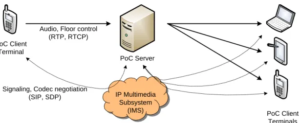
PoC provides a combination of VoIP telephony services and instant messaging style properties such as presence and messaging. The key advantage of PoC services is that a single user can reach an active talk group with just a button press, thus the user no longer needs to make call to each of the group. Like many VoIP solutions, the OMA
PoC solution is based on the classical Internet multimedia protocols (Figure 2.4). PoC Server PoC Client Terminal PoC Client Terminals IP Multimedia Subsystem (IMS) Signaling, Codec negotiation
(SIP, SDP)
Audio, Floor control (RTP, RTCP)
Figure 2.4: OMA specified PoC architecture
PoC Signaling
PoC signaling for session establishment is based on the Session Initiation Protocol (SIP) [41]. SIP is a text based end-to-end application layer protocol used to estab-lish, modify and terminate multimedia (e.g., audio, video) sessions. SIP can run on top of several transport layer protocols such as TCP, UDP and SCTP. There are several functional entities comprised the SIP architecture includes: user agent client, user agent server, registrar server, proxy server, redirect server, location server and back-to-back user agent. Like Hypertext Transfer Protocol (HTTP), SIP is based on request-response model. It defines INVITE, BYE, REGISTER, OPTIONS, etc. request messages, several provisional and final response messages.
During establishing PoC session, Session Description Protocol (SDP) is used in a SIP message body to negotiate codecs and other media related parameters between two parties in the fashion of offer/answer model. Media parameters may be re-negotiated in certain cases while ongoing voice session.
PoC Speech
PoC speech is transmitted in Real-time Transport Protocol (RTP) [42] packets. RTP is an IP-based protocol providing support of real-time data such as audio and video
streams. RTP is typically run on top of UDP to make use of its multiplexing and checksum functions. To deliver media streams timely, RTP includes time stamping, sequence numbering and other mechanisms to take care of timing issues. The re-ceiving PoC client uses the timestamp to reconstruct the original timing in order to play out data in correct rate. The RTP source identification allows the receiving application to know where the data is coming from.
RTP is designed to work in conjunction with the auxiliary control protocol, RTP Control Protocol (RTCP), to get feedback on the quality of data transmission and information about participants in the ongoing session. In the OMA PoC, RTCP provides floor control through arbitrating requests from PoC clients for the right to send media.
2.6
Summary
In this chapter, we have presented Delay-Tolerant Networking (DTN) concepts. DTN is designed to address communication requirements specific to challenged net-working environments, which include intermittent connectivity, long or variable de-lay, high error rates and low bit rates. In such scenarios, traditional Internet proto-cols may perform poorly or may not work at all.
In DTN, application data is carried over variable-length bundles. The bundles may be stored persistently in the intermediate nodes until the next contact becomes avail-able. This allows DTN not to rely on stable end-to-end path for communication at any point of time unlike Internet. Bundle protocol, which we have discussed here, is the primary protocol of DTN. The bundle protocol operates as an overlay on top of wide range of network types, while the convergence layer performs mapping be-tween bundle protocol and network-specific lower layers. Several convergence layer adapters (CLAs) can be integrated in a bundle node which enables bundle protocol agent (BPA) to interoperate with heterogeneous underlying networks.
Routing is one of the biggest open issues in DTNs. In this chapter, we have also introduced various routing approaches based on deterministic and stochastic DTNs. Deterministic routing schemes work on the assumption of having complete or partial knowledge of the network topology in advance. On the other hand, the information
about the network topology is totally unknown for stochastic cases. However none of the routing approaches are treated as perfect for DTNs.
The OMA specified PoC architecture has been introduced briefly in this chapter. The traditional PoC services rely on Internet protocols which require stable end-to-end path for successful operations. This may subject to abnormal communication experience in the mobile DTNs where end-to-end path may not exist at any given time. In this thesis we develop DT-Talkie which enables mobile users to communi-cate in the infrastructure-less and other challenged environments in the walkie-talkie fashion. In the next chapter, we describe the high-level architectural concepts of the DT-Talkie.
3
System Architecture
As the Open Mobile Alliance (OMA) specified Push-to-talk over Cellular (PoC) ser-vice works over either cellular networks or operator independent wireless networks, it is not very well-suited for infrastructure-less and challenged networks. In the regular PoC services, several round-trip messages are required to exchange in order to establish a PoC session. After establishing the session, voice data is transferred back and forth in the semi real-time fashion between endpoints either directly or via infrastructure. These services work well in the scenarios (e.g., Internet) when round-trip delays are significantly short. But in a DTN environment of high end-to-end delay and high error rates, the PoC session might not be established in the first place, or huge packet loss may lead to degraded voice quality. Overall, the traditional approach of voice communication would be unrealistic in the disrupted environments.
Our aim is to define requirements for practical voice communication in the mobile DTNs, in which speech quality is not affected, but the voice session can be less interactive due to delay. To avoid unwanted round-trip message exchanges for ses-sion establishment, sesses-sion parameters and optionally other contents can be bundled along with recorded voice messages. In order to achieve this, we must define how different data chunks can be aggregated together into larger data structures, and how these structures are placed into bundles. It might happen that the mobile end-points experience better link connectivity while ongoing voice session. In such cases we must provide means for speeding up the session interactivity.
In this chapter, we provide a high-level overview about the DT-Talkie system and then proceed to discuss the system design broadly. We also describe the fragmen-tation approach that is applied to the DT-Talkie. Finally some mechanisms to mitigate the codec interoperability issues are suggested.
3.1
System Concepts of the DT-Talkie
The existing PoC solutions are mainly infrastructure-based and rely on stable end-to-end path for successful communication. But the mobile nodes may roam in the environments, where infrastructure is not available or unreliable end-to-end path does exist. In such cases, those PoC solutions may exhibit poor performance or
may even fail completely. So a new approach is necessitated to define for enabling voice communication in the infrastructure-less and other challenged networking en-vironments. In this thesis, we devise a system called DT-Talkie in which the DTN concept of asynchronous message forwarding is applied to transport voice messages in the infrastructure-less and challenged networks.
Figure 3.1 depicts the general processing steps of the DT-Talkie. Basically in the DT-Talkie, voice messages are captured and then encoded using a preconfigured codec. It might happen that the destination endpoint does not have support of the codec to decode and playback voice messages. One solution to deal with the problem can be that two endpoints negotiate on a common codec prior to voice message transfer like traditional PoC services. But this requires several round-trip message exchanges, which is not feasible in the high delay environment. In order to handle the issue we primarily provide support of more codecs to the DT-Talkie which can make the system more codec-interoperable. We also suggest some other approaches concerning codec interoperability issues, which are discussed later in this chapter. Audio Encoding Application Level Framing Bundling Bundle Protocol Service PCM Voice Headers MIME Message Optional Contents Voice Headers DTN Bundle MIME Message Encoded Voice DTN
Figure 3.1: General processing steps of the DT-Talkie
However after encoding the voice messages, the next step is to encapsulate them into bundles. Rather than simply bundling the unstructured voice messages, we use a framing mechanism which enables aggregation of other optional contents in con-junction with the voice messages. The bundles are then sent using the DTN bundle protocol services, which are forwarded reliably on the way to the destination in the store-carry-forward fashion. The bundles are decapsulated after receiving to get the voice messages, which are played out after decoding.
in-depth discussion about the system design with the aid of a one-to-one communication scenario. Suppose user A attempts to send a voice message to User B and both have DTN communication capabilities.
3.1.1 Audio Encoding
DT-Talkie captures voice messages from the audio source (e.g., microphone) of user A. The captured voice messages can be sent in either uncompressed or compressed format. The uncompressed audio formats, often referred to as PCM formats, do not use any compression mechanism. This means all the audio information is available at the cost of large file size. A WAV audio file is an example of uncompressed audio. The compressed audio can be of two types: lossless and lossy. Lossless audio com-pression applies to an uncompressed audio file without any loss of audio information, whereas lossy compression technique results better compression through eliminat-ing redundant and unnecessary audio information. Since lossy compression discards only those parts of audio which cannot be perceived by human auditory system, it has very little impact on audio quality. For example MP3 and G729 audio files use lossy compression. DT-Talkie supports transmission of voice messages both in uncompressed (WAV) and compressed (MP3 and G729) audio format. In this the-sis, there is no mechanism employed in the DT-Talkie to negotiate audio encoding format before delivering voice messages. Rather we assume a default audio format for a particular voice session, which is preconfigured in both side of user A and user B.
3.1.2 Application Layer Framing
DT-Talkie allows sending optionally other contents (e.g., image, electronic business card) together with a voice message. The image can be either User A’s profile picture or instant snapshot from the devices camera. The electronic business card (vCard) [43] is often attached to email messages, but can be significantly used in the DT-Talkie to provide information related to sender’s name, email address, phone numbers and so on. Application layer framing mechanism is applied to place the voice message and other contents into a single structure. We use MIME (Multipur-pose Internet Mail Extension) [44] for this pur(Multipur-pose.
web-browsers to send and receive non-ASCII messages (e.g., image, audio and video) via the Internet. A MIME message includes both data and metadata. MIME metadata consists of HTTP-style headers and MIME boundary delimiters. Different types of contents can be encapsulated in different parts of a multipart MIME message and theContent-Type header field specifies the type of the content in each part. In such multipart messages theContent-Typeheader also includes a boundary attribute that is used to delimit the message parts. MIME provides the support of custom user-defined headers (prefixed with “X-”) to be used for application-specific purposes. Based on MIME standard, S/MIME provides cryptographic security services (e.g., authentication, encryption) for the applications that transport MIME data.
Figure 3.2 presents an example MIME message in short form which is generated in a DT-Talkie session. We add X-Bundle-Destination header in the MIME message to refer two types of DT-Talkie communication. The value of the above header is either singleton for one-to-one or multinode for group communication. The value of the X-Bundle-Type header can be either message when the DT-Talkie sends a full-length voice message or fragment if the fragments of the voice message are sent. The encoded voice message is aggregated as a body part of type audio/G729 and the image as another body part of type image/jpeg. The business card information is aggregated in the MIME message with type text/x-vcard. The vCard contains a formatted name string which can be used as a display name and an Internet email address.
Some protocols cannot carry binary data, or data with a line length of greater than 1000 lines - specifically Simple Mail Transfer Protocol (SMTP) has both those restrictions. The MIME messages contains binary data need to be transformed in such way so that the messages will be transportable by those restricted protocols. To achieve this, a binary-to-text encoding mechanism is required to apply. Base64, one of the MIME supported encoding scheme, is used to transform binary data (e.g., images, audio) into a text string that contains only US-ASCII characters. But the pitfall of the scheme is that it increases data volume by 33% [44]. In our case the restrictions do not apply because we use DTN transport which supports transmission of binary data without any limitation; thus reduces overall message overhead.
X-Bundle-Destination: singleton X-Bundle-Type: message
MIME-Version: 1.0
Content-Type: multipart/mixed; boundary="=-UL99WySTLs0AAPGPLgtN" --=-UL99WySTLs0AAPGPLgtN Content-Type: audio/G729 1ÍGŸTS§QâXJqßÚщsaÍ^cÃÝÛ”Gl/Œ^ňØð[;aöÁÆ ’ÿhT©— _ŢBÃT^li˜Ov)ÿQäuúˆ+!š¥öùÙ"=8A€¤òn={Tfå:\yðâÔûkÈú{äýIsßm \ ... --=-UL99WySTLs0AAPGPLgtN— Content-Type: image/jpeg |]ªëeõÙ»+ö8PIi*nC6î`Œ¨aŒ|ÊsšâüWc7‰üG§ê7¶ö§GÓbka$óÁÛ¶äV!w`~ µÅøÁŸ`ƒK¾û4:¥»KöR¾Ê¹B àþcŠó½[MBå,m.o4Éæ´0HË6øç ... --=-UL99WySTLs0AAPGPLgtN Content-Type: text/x-vcard BEGIN:VCARD VERSION:2.1 FN:Forrest Gump EMAIL;INTERNET:forrestgump@example.com ... END:VCARD --=-UL99WySTLs0AAPGPLgtN
Figure 3.2: Sample MIME message generated in a DT-Talkie session
3.1.3 Bundle Addressing
After aggregating encoded voice and image into a MIME message, the DT-Talkie application encapsulates the MIME message into a DTN bundle. Now the bundle is needed to be addressed for transmission. As described before, All the endpoints in the DTN domain are identified by an URI-like endpoint identifier (EID), which has the general form of<scheme name>:<scheme-specific part>. Every node has a unique singleton EID but can register to any number of multicast EIDs. When an application wishes to receive bundles destined to a particular EID, it registers the corresponding EID with its local DTN node.
Basically the bundle protocol is not limited to a specific URI scheme - any valid scheme (e.g., dtn:, http:, mailto:) can be used in an EID. The scheme name defines a set of rules that determine how the scheme-specific part should be interpreted [16].
However the “dtn:” scheme is adopted as a default scheme in the DTN2 reference implementation using the structure of “dtn://node-id/application-id” (described in the earlier versions of the bundle protocol) [45], where node-id identifies a particular dtn daemon and application-id identifies a particular application that uses the above daemon to interface to the DTN system.
Since our DT-Talkie implementation uses DTN2, so we must use “dtn:” for all EIDs. “<host>.dtn” is used as node-id and “dttalkie” is used as application-id (e.g., dtn://nokia-n810.dtn/dttalkie) to identify DTN nodes running the DT-Talkie application. Other implementations of the DTN bundle protocol might choose to use different URI schemes for bundle addressing, rather than the “dtn:” scheme. The impact of using different URI schemes on our application is minimal.
3.1.4 Bundle Routing and Delivery
The DT-Talkie on the side of user A sends the bundle in the mobile DTNs, using the services provided by the bundle protocol. We use Epidemic routing protocol to forward the bundle along the path from the source to the destination. Epidemic routing protocol is chosen because of its simplicity and higher message delivery rates. Nevertheless we will observe the behavior of DT-Talkie in the simulation environ-ment using other DTN routing protocols in Chapter 5. After sending the bundle, it traverses through the network in the store-carry-and-forward manner, until the destination node is reached.
As soon as user B receives the bundle, it is decapsulated to extract the MIME message. The DT-Talkie then parses the MIME message to get the encoded voice message and other optional contents if any. TheContent-Type header of the received MIME message provides information about the codec through which the voice mes-sage was encoded. The DT-Talkie then decodes the voice data using the codec information and starts playback in the audio sink (e.g., speaker) of user B. Finally appropriate action is applied to the optional contents (e.g., image is shown in the GUI).
The aforementioned approach is applicable for user B if he wants to answer user A and in this way the users can exchange several messages until the end of a voice session. When the first exchange of voice messages between user A and user B is
taken place, the DT-Talkie considers that two user are actively communicating in the session. In this active voice session, the voice messages from other users are stored locally instead of playing out immediately. So the active users are not interrupted while communication and they can playback the stored voice messages later after the active voice session is over.
3.1.5 Group Communication
The epidemic routing protocol which we use primarily in the DT-Talkie one-to-one communication, is a perfect fit for asynchronous style of group communication. Group communication may be applicable in many potential DTN applications where mobile nodes are required to collaborate closely in the infrastructure-less environ-ment. For example, in the disaster situations, a rescue worker wants to inform other workers of a group about the current local condition through sending voice messages.
To perform group communication in the DT-Talkie, the same concept of one-to-one communication is applied with the exception that the voice messages are destined to a multicast EID. We define the structure of multicast EID as dtn://<group-name>.dtn/dttalkie (e.g., dtn://netlab.dtn/dttalkie), which is equivalent to single-ton EID. If the DT-Talkie enabled users want to receive voice messages from a particular group, they must register with the corresponding EID.
3.2
Voice Message Fragmentation
In some scenarios it is not always good idea to send large voice messages in one transmission. As we mentioned before that the DTN bundles are variable in length, so the bundle size may vary from kilobytes to megabytes and even gigabytes. Gen-erally large messages lead to longer transfer times and the contact duration in the opportunistic DTN environment may be too short to reliably transmit a large single message. This implies splitting a large message into smaller pieces through frag-mentation to enable communication over short-lived links.
In the usual one-to-one DT-Talkie communication, users listen to a received voice message and attempt to record another voice message for the next transmission. So to get the next voice message, the receiver used to wait for a while (sender’s listening time + sender’s recording time + transmission time). For example, if user B received