1 Seagoing
Ships
5
Structural Rules for Container Ships
DNV GL SE
(Germanischer Lloyd SE has on 29 January 2014 changed its name to DNV GL SE. Any references in this
document to Germanischer Lloyd or GL shall therefore also be a reference to DNV GL SE.)
Head Office
Brooktorkai 18, 20457 Hamburg, Germany
Phone: +49 40 36149-0
Fax: +49 40 36149-200
www.dnvgl.com
"General Terms and Conditions" of the respective latest edition will be applicable
(see Rules for Classification and Construction, I - Ship Technology, Part 0 - Classification and Surveys).
Reproduction by printing or photostatic means is only permissible with the consent of
DNV GL SE.
Table of Contents
Section 1 General, Definitions
A General ... 1- 1 B Note for Vibrations and Noise ... 1- 1 C Rounding-Off Tolerances ... 1- 1 D Regulations of National Administrations ... 1- 1 E Direct Calculations ... 1- 1 F Specific Programs related to Rules ... 1- 1
Section 2 Materials
A General ... 2- 1 B Hull Structural Steel for Plates and Sections ... 2- 1 C Forged Steel and Cast Steel ... 2- 1 D Aluminium Alloys ... 2- 1 E Austenitic Steels ... 2- 1
Section 3 Design Principles
A General ... 3- 1 B Structural Members ... 3- 1 C Effective Breadth of Plating ... 3- 1 D Proof of Buckling Strength ... 3- 1 E Structural Details ... 3- 1 F Evaluation of Notch Stress ... 3- 1 G Corrosion Additions ... 3- 1 H Testing of Watertight and Weathertight Compartments ... 3- 1
Section 4 Design Loads
A General ... 4- 1 B External Sea Loads ... 4- 1 C Loads on Inner Decks ... 4- 1 D Loads on Tank Structures ... 4- 1 E Design Values of Acceleration Components ... 4- 1
Section 5 Longitudinal Strength
A General ... 5- 1 B Design Loading Conditions ... 5- 1 C Loading Guidance Information ... 5- 1 D Global Loads on the Ship's Hull and Design Stresses ... 5- 1 E Design Verification ... 5- 1 F Global Strength Analysis ... 5- 1
Section 6 Shell Structures
A General ... 6- 1 B Bottom Plating ... 6- 1 C Side Shell Plating ... 6- 1 D Strengthening of Bottom Forward ... 6- 1 E Strengthenings in Way of Propellers and Bilge Keels ... 6- 1 F Openings in the Shell Plating ... 6- 1 G Intentionally left blank ... 6- 1 H Intentionally left blank ... 6- 1 I Bulwark ... 6- 1
Section 7 Decks
A General ... 7- 1 B Strength Deck ... 7- 1 C Other Decks ... 7- 1 D Intentionally left blank ... 7- 1 E Intentionally left blank ... 7- 1
Section 8 Bottom Structures
A General ... 8- 1 B Single Bottom ... 8- 1 C Double Bottom ... 8- 1 D Bottom Structure in Machinery Spaces in Way of the Main Propulsion Plant ... 8- 1 E Sea chests ... 8- 1 F Transverse Thrusters ... 8- 1 G Docking Calculation ... 8- 1
Section 9 Framing System
A General ... 9- 1 B Transverse Framing ... 9- 1 C Bottom-, Side- and Deck Longitudinals, Side Transverses ... 9- 1
Section 10 Deck Beams and Supporting Deck Structures
A General ... 10- 1 B Deck Beams and Girders ... 10- 1 C Pillars ... 10- 1 D Cantilevers ... 10- 1 E Hatchway Girders and Girders Forming Part of the Longitudinal Hull Structure ... 10- 1
Section 11 Watertight Bulkheads
A General ... 11- 1 B Bulkhead plating ... 11- 1 C Stiffeners ... 11- 1 D Primary supporting members ... 11- 1 E Watertight longitudinal structures ... 11- 1 F Intentionally left blank ... 11- 1 G Shaft Tunnels ... 11- 1
Section 12 Tank Structures
A General ... 12- 1 B Scantlings ... 12- 1 C Tanks with Large Lengths or Breadths ... 12- 1 D Intentionally left blank ... 12- 1 E Detached Tanks ... 12- 1 F Potable Water Tanks ... 12- 1 G Swash Bulkheads ... 12- 1 H Fuel and Lubricating Oil Tanks in Double Bottom ... 12- 1 I Tanks for heated liquids ... 12- 1
Section 13 Stem and Sternframe Structures
A General ... 13- 1 B Stem ... 13- 1 C Sternframe ... 13- 1 D Propeller Brackets ... 13- 1 E Intentionally left blank ... 13- 1
Section 14 Rudder and Manoeuvring Arrangement
A General ... 14- 1 B Structural details ... 14- 1 C Materials ... 14- 1 D Rudder Force and Torque ... 14- 1 E Scantlings of the Rudder Stock ... 14- 1 F Rudder Couplings ... 14- 1 G Rudder Body, Rudder Bearings ... 14- 1 H Design Yield Moment of Rudder Stock ... 14- 1 I Stopper, Locking Device ... 14- 1 J Intentionally left blank ... 14- 1 K Devices for Improving Propulsion Efficiency ... 14- 1 L Intentionally left blank ... 14- 1
Section 15 Strengthening for Navigation in Ice
A General ... 15- 1 B Requirements for the Notations E1 - E4 ... 15- 1 C Requirements for the Notation E ... 15- 1
Section 16 Superstructures and Deckhouses
A General ... 16- 1 B Strengthenings at the ends of superstructures and deckhouses ... 16- 1 C Transverse structure of superstructures and deckhouses ... 16- 1 D Side Plating and Decks of Superstructures ... 16- 1 E Superstructure End Bulkheads and Deckhouse Walls ... 16- 1 F Decks of Short Deckhouses ... 16- 1 G Intentionally left blank ... 16- 1 H External Funnel Walls ... 16- 1 I Breakwater ... 16- 1 J Recommendations regarding deckhouse vibration ... 16- 1
Section 17 Cargo Hatchways
A General ... 17- 1 B Hatch Covers ... 17- 1 C Hatch Coamings and Girders ... 17- 1 D Weather tightness of hatch cover systems ... 17- 1
Section 18 Equipment A General ... 18- 1 B Equipment numeral ... 18- 1 C Anchors ... 18- 1 D Chain Cables ... 18- 1 E Chain Locker ... 18- 1 F Mooring Equipment ... 18- 1 G Towing Equipment ... 18- 1 H Towing and Mooring Arrangement Plan ... 18- 1
Section 19 Welded Joints
A General ... 19- 1 B Design ... 19- 1 C Stress Analysis ... 19- 1
Section 20 Fatigue Strength
A General ... 20- 1 B Fatigue Strength Analysis for Free Plate Edges and for Welded Joints using Detail
Classification ... 20- 1 C Fatigue Strength Analysis for Welded Joints Based on Local Stresses ... 20- 1
Section 21 Hull Outfit
A General ... 21- 1 B Partition Bulkheads ... 21- 1 C Intentionally left blank ... 21- 1 D Side Scuttles, Windows and Skylights ... 21- 1 E Side Shell Fittings, Scuppers and Freeing Ports ... 21- 1 F Air Pipes, Overflow Pipes, Sounding Pipes ... 21- 1 G Ventilators ... 21- 1 H Stowage of Containers ... 21- 1 I Lashing Arrangements ... 21- 1 J Intentionally left blank ... 21- 1 K Life Saving Appliances ... 21- 1 L Signal and Radar Masts ... 21- 1 M Loading and Lifting Gear ... 21- 1 N Protection of the Crew ... 21- 1 O Means for Safe Passage of Crew ... 21- 1 P Smaller Openings and Hatches ... 21- 1 Q Engine and Boiler Room Hatchways ... 21- 1 R Doors ... 21- 1 S Machinery Space Openings ... 21- 1 T Shell Doors ... 21- 1
Section 22 Structural Fire Protection
A General ... 22- 1 B Intentionally left blank ... 22- 1 C Intentionally left blank ... 22- 1 D Intentionally left blank ... 22- 1 E Cargo Ships of 500 GT and over ... 22- 1 F Intentionally left blank ... 22- 1 G Intentionally left blank ... 22- 1
Section 23 Intentionally left blank
Section 24 Intentionally left blank
Section 25 Intentionally left blank
Section 26 Intentionally left blank
Section 27 General Arrangement
A General ... 27- 1 B Subdivision ... 27- 1 C Arrangement ... 27- 1 D Accessibility ... 27- 1
Section 28 Stability of Cargo Ships
A General ... 28- 1 B Intact Stability ... 28- 1 C Damage Stability ... 28- 1
Section 29 Intentionally left blank
Section 30 Intentionally left blank
Section 31 Intentionally left blank
Section 32 Intentionally left blank
Section 34 Special Requirements for In-Water Surveys
A General ... 34- 1 B Special Arrangements for In-Water Surveys ... 34- 1 C Documents and Trials ... 34- 1
Section 35 Corrosion Protection
A General Instructions ... 35- 1 B Shop Primers ... 35- 1 C Hollow Spaces ... 35- 1 D Combination of Materials ... 35- 1 E Fitting-Out and Berthing Periods ... 35- 1 F Corrosion Protection of Ballast Water Tanks ... 35- 1 G Corrosion Protection of Cargo Holds ... 35- 1 H Corrosion Protection of the Underwater Hull ... 35- 1 I Intentionally left blank ... 35- 1
Section 36 Cargo Hold Analysis
A General ... 36- 1 B Structural Idealization ... 36- 1 C Design Loads ... 36- 1 D Boundary Conditions ... 36- 1 E Model Check ... 36- 1 F Evaluation of Results ... 36- 1
Annex A Load Line Marks
A Load Line Marks of GL ... A- 1
Annex B Ice Class Draught Marking
A Ice Class Draught Marking of GL ... B- 1
Annex C Certification of Hull Response Monitoring Systems for Container Ships
A General ... C- 1 B System Types ... C- 1 C System Requirements ... C- 1 D Commissioning ... C- 1 E Survey Requirements ... C- 1 F Guidance on Selection of Hull Response Monitoring System ... C- 1
Section 1
General, Definitions
A General ... 1-1 B Note for Vibrations and Noise ... 1-5 C Rounding-Off Tolerances ... 1-5 D Regulations of National Administrations ... 1-5 E Direct Calculations ... 1-6 F Specific Programs related to Rules ... 1-6
A General
A.1 Application
A.1.1 Ships intended to get the Notation CONTAINER SHIP and having a length L of 150 m and above and an unlimited range of service are to be in compliance with the sections of this chapter.
A.1.2 Intentionally left blank.
A.1.3 Passages of this chapter printed in italics contain recommendations and notes which are not part of the Classification Rules.
A.2 References
A.2.1 Application, characters of classification and class notations
For application, characters of classification and class notations see the GL Rules for Classification and Surveys (I-0), Section 2.
A.2.2 International Conventions and Codes
A.2.2.1 Paragraphs of this section are based on the following international convention(s) and/or code(s):
IACS UR S2 Rev.1 IACS UR S21A
ICLL containing all amendments up to 1st July 2010
MARPOL 73/78 containing all amendments up to 1st February 2012
At the end of each relevant paragraph of this section, the corresponding paragraphs of the international convention(s) and/or code(s) are given in brackets.
A.2.2.2 Where reference is made of international Conventions and Codes these are defined as fol-lows:
ICLL
International Convention on Load Lines, 1966, as amended.
MARPOL
International Convention for the Prevention of Pollution from Ships, 1973 including the 1978 Protocol as amended.
SOLAS
A.3 Definitions A.3.1 Parameters
Considering the range of application, definitions of parameter are made at different locations of this chap-ter as follows:
parameters only used in one paragraph are defined in the specific paragraph
parameters used in more than one paragraph of the same section are defined at the beginning of the specific section
parameters used in more than one section are defined in the following paragraphs
A.3.1.1 Principal dimensions Length L
The length L [m] is the distance in metres on the summer load waterline from the fore side of the stem to the centre of the rudder stock. L is not to be less than 96 % and need not be greater than 97 % of the ex-treme length of the summer load waterline. In ships with unusual stern and bow arrangement, the length L will be specially considered.
(IACS UR S2.1)
Length Lc
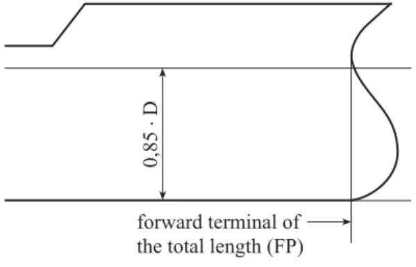
The length Lc [m] is to be taken as 96 % of the total length on a waterline at 85 % of the least moulded depth Hc measured from the top of the keel, or as the length from the fore side of the stem to the axis of the rudder stock on that waterline, if that be greater.
For ships without a rudder stock, the length Lc is to be taken as 96 % of the waterline at 85 % of the least moulded depth.
Where the stem contour is concave above the waterline at 85 % of the least moulded depth, both the for-ward terminal of the total length and the fore side of the stem respectively shall be taken at the vertical projection to the waterline of the aftermost point of the stem contour (above that waterline) (see Fig. 1.1).
(ICLL Annex I, I, 3(1); MARPOL 73/78 Annex 1, 1.19)
0,85
×
D
forward terminal of the total length (FP)
Fig. 1.1 Length Lc in case of concave stern contour
Forward perpendicular F.P.
The forward perpendicular coincides with the foreside of the stem on the waterline on which the respec-tive length L or Lc is measured.
Breadth B
The breadth B [m] is the greatest moulded breadth of the ship.
Depth H
The depth H [m] is the vertical distance, at the middle of the length L, from the base line to top of the deck beam at side on the uppermost continuous deck.
In way of effective superstructures the depth is to be measured up to the superstructure deck for deter-mining the ship's scantlings.
Depth Hc
The moulded depth Hc [m] is the vertical distance measured from the top of the keel to the top of the freeboard deck beam at side. In wood and composite ships the distance is measured from the lower edge of the keel rabbet. Where the form at the lower part of the midship section is of a hollow character, or where thick garboards are fitted, the distance is measured from the point where the line of the flat of the bottom continued inwards cuts the side of the keel.
In ships having rounded gunwales, the moulded depth is to be measured to the point of intersection of the moulded lines of deck and sides, the lines extending as though the gunwale were of angular design. Where the freeboard deck is stepped and the raised part of the deck extends over the point at which the moulded depth is to be determined, the moulded depth is to be measured to a line of reference extending from the lower part of the deck along a line parallel with the raised part.
(ICLL Annex I, I, 3(5))
Draught T
The draught T [m] is the vertical distance at the middle of the length L from base line to freeboard mark-ing for summer load waterline.
Frame spacing a
The frame spacing a [m] will be measured from moulding edge to moulding edge of frame.
Block coefficient CB
Moulded block coefficient at load draught T, based on length L. 3
B moulded volume of displacement [m ] at C T L B T (IACS UR S2.2) Ship's speed v0
Maximum service speed [kn], which the ship is designed to maintain at the summer load line draught and at the propeller RPM corresponding to MCR (Maximum Continuous Rating).
In case of controllable pitch propellers the speed v0 is to be determined on the basis of maximum pitch.
A.3.1.2 Material properties Yield strength ReH
The yield strength ReH [N / mm2] of the material is defined as the nominal upper yield point. In case of materials without a marked yield point, the proof stress Rp is to be used instead. See also Section 2, D, Section 2, E and Principles and Test Procedures (II-1-1), Section 2, D.
Tensile strength Rm
Rm [N/mm2] is the minimum tensile strength of the material. See also Principles and Test Procedures (II-1-1), Section 2, D.
Proof stress Rp
The proof stress Rp [N / mm2] is the stress that will cause a specified permanent extension of a specimen of a tensile test. The specified permanent extension is denoted in the index.
Rp0.2= 0.2 % proof stress Rp1.0= 1.0 % proof stress
See also Principles and Test Procedures (II-1-1), Section 2, D.
Young's modulus E
E : Young's modulus [N / mm2], defined as:
5 2
5 2
E 0.69 10 N / mm for aluminium alloys
A.3.2 Decks Bulkhead deck
Bulkhead deck is the deck up to which the watertight bulkheads are carried.
Freeboard deck
1. The freeboard deck is normally the uppermost complete deck exposed to weather and sea, which has permanent means of closing all openings in the weather part thereof, and below which all open-ings in the side of the ship are fitted with permanent means of watertight closing.
2. Lower deck as a freeboard deck
At the option of the owner and subject to the approval of the Administration, a lower deck may be designated as the freeboard deck provided it is a complete and permanent deck continuous in a fore and aft direction at least between the machinery space and peak bulkheads and continuous athwartships.
For details of the definition, see ICLL. (ICLL Annex I, I, 3(9))
Strength deck
The strength deck is:
the uppermost continuous deck which is forming the upper flange of the hull structure
a superstructure deck which extends into 0.4 L amidships and the length of which exceeds 0.15 L
Weather deck
All free decks and parts of decks exposed to the sea are defined as weather deck.
Lower decks
Starting from the first deck below the uppermost continuous deck, the decks are defined as 2nd, 3rd deck, etc.
Superstructure decks
The superstructure decks situated immediately above the uppermost continuous deck are termed fore-castle deck, bridge deck and poop deck. Superstructure decks above the bridge deck are termed 2nd, 3rd superstructure deck, etc.
A.3.3 Position of hatchways, doorways and ventilators
For the arrangement of hatches, doors and ventilators the following areas are defined: Position 1
◦ on exposed freeboard decks ◦ on raised quarter decks
◦ on the first exposed superstructure deck above the freeboard deck within the forward quarter of Lc
Position 2
◦ on exposed superstructure decks aft of the forward quarter of Lc located at least one standard height of superstructure above the freeboard deck
◦ on exposed superstructure decks within the forward quarter of Lc located at least two standard heights of superstructure above the freeboard deck
B
Note for Vibrations and Noise
B.1 Mechanical vibrations
Operating conditions which are encountered most frequently should be kept free as far as possible from resonance vibrations of the ship hull and individual structural components. Therefore, the exciting forces coming from the propulsion plant and pressure fluctuations should be limited as far as possible. Beside the selection of the propulsion units particular attention is to be given to the ship's lines including the stern post, as well as to the minimisation of possible cavitation. In the shaping of the bow it should be kept in mind that a large flare above the waterline will not only cause very high local slamming pressures, but will also excite increasingly whipping vibrations of the ship's hull. If critical excitation loads cannot be elimi-nated, appropriate measures are to be taken on the basis of theoretical investigations at an early design stage.
For example, the risk of large global and local structural vibrations can be minimized by a global or local vibration analysis, respectively, to be conducted during the steel structures design phase.
Limit values for vibrations aboard ships may be assessed under several aspects. If the application of oth-er national or intoth-ernational rules or standards is not mandatory, the following guidelines and regulations are recommended:
Vibration load to the crew:
measurement and analysis techniques according to ISO 6954, ed. 2000
limit values according to ISO 6954, depending on ship type and location within the ship. (the GL Service Group Vibration is ready to provide support to this activity)
ships flying the German Flag according to the Guidelines of the Accident Prevention Regulations of BG Verkehr Dienststelle Schiffssicherheit (BG Verkehr Ship Safety Division)
vibrations of machinery, installations and other equipment according to Machinery Installations (I-1-2), Section 1
B.2 Noise
Suitable precautions are to be taken to keep noises as low as possible particularly in the crew's quarters, working spaces, passengers' accommodation, etc.
Attention is drawn to regulations concerning noise level limitations, if any, of the flag administration.
C Rounding-Off
Tolerances
Where in determining plate thicknesses in accordance with the provisions of the following Sections the figures differ from full or half mm, they may be rounded off to full or half millimetres up to 0.2 or 0.7; above 0.2 or 0.7 mm they are to be rounded up.
If plate thicknesses are not rounded the calculated required thicknesses is to be shown in the drawings. The section moduli of profiles usual in the trade and including the effective width according to Section 3, C and Section 3, D may be 3 % less than the required values according to the rules for dimensioning of this chapter.
D
Regulations of National Administrations
For the convenience of the user of these Rules several Sections contain for guidance references to such regulations of national administrations, which deviate from the respective rule requirements of this Society but which may have effect on scantlings and construction. These references have been specially marked. Compliance with these regulations of national administrations is not conditional for class assignment.
E Direct
Calculations
E.1 In order to increase the flexibility in the structural design of ships GL also accepts direct calcu-lations with computer programs. The aim of such analyses should be the proof of equivalence of a design with the rule requirements.
E.2 For such calculation the computer model, the boundary condition and load cases are to be agreed upon with GL. The calculation documents are to be submitted including input and output. During the examination it may prove necessary that GL perform independent comparative calculations.
E.3 The choice of computer programs according to "State of the Art" is free. The programs may be checked by GL through comparative calculations with predefined test examples. A generally valid ap-proval for a computer program is, however, not given by GL.
E.4 GL is prepared to carry out the following calculations of this kind within the marine advisory services:
E.4.1 Strength
Linear and/or non-linear strength calculations with the FE-method:
For an automated performance of these calculations, a number of effective pre- and post processing pro-grammes is at disposal:
calculation of seaway loads as per modified strip method or by 3D-panel method calculation of resultant accelerations to ensure quasi-static equilibrium
calculation of composite structures
evaluation of deformations, stresses, buckling behaviour, ultimate strength and local stresses, as-sessment of fatigue strength
E.4.2 Vibrations
Calculation of free vibrations with the FE-method as well as forced vibrations due to harmonic or shock excitation:
global vibrations of hull, aft ship, deckhouse, etc.
vibrations of major local components, such as rudders, radar masts, etc. local vibrations of plate fields, stiffeners and panels
vibrations of simply or double-elastically mounted aggregates
A number of pre- and post processing programs is available here as well for effective analyses: ◦ calculation of engine excitation (forces and moments)
◦ calculation of propeller excitation (pressure fluctuations and shaft bearing reactions) ◦ calculation of hydrodynamic masses
◦ graphic evaluation of amplitude level as per ISO 6954 recommendations or as per any other standard
◦ noise predictions
E.4.3 Intentionally left blank
F
Specific Programs related to Rules
F.1 General
GL has developed the computer program "POSEIDON" as an aid to fast and reliable dimensioning a hull's structural members according to GL Rules, and for direct strength calculations.
F.2 POSEIDON
POSEIDON includes both the traditional dimensioning as well as the automatic optimisation of scantlings by means of direct calculations according to the FE-method.
POSEIDON is supported on PCs by Microsoft Windows , and a hotline has been set up to assist users. Further information is available via the GL-homepage, at inspection offices world-wide and at GL Head Office.
F.3 GL RULES and Programs
GLRP is available on CD-ROM. It includes the wording of GL-Rules and an elementary program for di-mensioning the structural members of the hull.
Section 2
Materials
A General ... 2-1 B Hull Structural Steel for Plates and Sections ... 2-2 C Forged Steel and Cast Steel ... 2-7 D Aluminium Alloys ... 2-7 E Austenitic Steels ... 2-8
A General
A.1 References
International conventions and codes
Paragraphs of this section are based on the following international convention(s) and/or code(s): IACS UR S4 Rev.3
IACS UR S6 Rev.6
At the end of each relevant paragraph of this section, the corresponding paragraphs of the international convention(s) and/or code(s) are given in brackets.
A.2 Definitions
Normal strength hull structural steel
Normal strength hull structural steel is a hull structural steel with yield strength ReH of 235N / mm2 and a tensile strength Rm of 400–520N/mm2.
Depending of their toughness properties, normal strength hull structural steel is grouped into the following grades:
GL–A GL–B GL–D GL–E
Higher strength hull structural steels
Higher strength hull structural steel is a hull structural steel, the yield and tensile properties of which ex-ceed those of normal strength hull structural steel. According to the GL Rules for Metallic Materials (II-1), for three groups of higher strength hull structural steels the yield strength ReH has been fixed at 315, 355, 390 and 460 N / mm2 respectively.
The application of higher strength hull structural steel with a nominal yield stress of 460 N / mm2 is in gen-eral limited to structural members of the upper hull of container ships according to the respective GL Supplementary Rules.
Depending of their toughness properties, higher strength hull structural steel is grouped into the following grades:
GL–A 32 / 36 / 40 GL–D 32 / 36 / 40 GL–E 32 / 36 / 40 GL–F 32 / 36 / 40
Material Factor k
The material factor k is to be determined by the following formulae:
k 1 for ReH 235 N / mm2 k 0.78 for ReH 315 N / mm2 k 0.72 for ReH 355 N / mm2 k 0.66 for ReH 390 N / mm2 k 0.62 for ReH 460 N / mm2 eH 295 k R 60 for 2 eH 235 < R 390 N / mm and ReH≠ 315 or 355 N / mm2 (IACS UR S4)
B
Hull Structural Steel for Plates and Sections
B.1 General
B.1.1 All materials to be used for the structural members indicated in the Construction Rules are to be in accordance with the GL Rules for Metallic Materials (II-1).
Materials the properties of which deviate from these Rule requirements may only be used upon special approval.
B.1.2 In general ships are to be made out of normal and higher strength hull structural steels.
According to B.1.1 higher strength hull structural steel with yield strength in the range of 235 < ReH < 390 N / mm2 and ReH≠ 315 or 355 N / mm2 may be accepted upon special approval.
B.1.3 Where structural members are completely or partly made from higher strength hull structural steel, a suitable Notation will be entered into the ship's certificate.
B.1.4 In the drawings submitted for approval it is to be shown which structural members are made of higher strength, high strength and/or brittle crack arrest hull structural steel. These drawings are to be placed on board in case any repairs are to be carried out.
B.2 Material selection for the hull B.2.1 General
For the material selection for hull structural members material classes and grades as given in B.2.2 and B.2.3 are defined.
For structural members not specifically mentioned in B.2.2 and B.2.3, grade A / AH may generally be used. However, GL may require also higher grades depending on the stress level.
The material grade requirements for hull members of each class depending on the thickness are defined in Table 2.8.
The steel grade is to correspond to the as-built plate thickness and material class. (IACS UR S6.1)
B.2.2 Material selection for longitudinal structural members
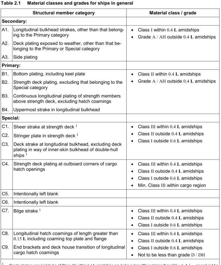
Materials in the various strength members are not to be of lower grade than those corresponding to the material classes and grades specified in Table 2.1 - Table 2.8. General requirements are given in Table 2.1, while additional minimum requirements are given in the following:
Table 2.2 for ships with single strength deck, Table 2.4 for ships with length exceeding 250 m, Table 2.6 for ships with ice strengthening, Table 2.7 for ships with cranes.
(IACS UR S6.1)
Table 2.1 Material classes and grades for ships in general
Structural member category Material class / grade Secondary:
A1. Longitudinal bulkhead strakes, other than that
belong-ing to the Primary category Class Grade IA / AH within outside 0.4 L amidships 0.4 L amidships A2. Deck plating exposed to weather, other than that
be-longing to the Primary or Special category A3. Side plating
Primary:
B1. Bottom plating, including keel plate Class II within 0.4 L amidships Grade A / AH outside 0.4 L amidships B2. Strength deck plating, excluding that belonging to the
Special category
B3. Continuous longitudinal plating of strength members above strength deck, excluding hatch coamings B4. Uppermost strake in longitudinal bulkhead
Special:
C1. Sheer strake at strength deck1 Class III within 0.4 L amidships
Class II outside 0.4 L amidships Class I outside 0.6 L amidships C2. Stringer plate in strength deck1
C3. Deck strake at longitudinal bulkhead, excluding deck plating in way of inner-skin bulkhead of double-hull ships1
C4. Strength deck plating at outboard corners of cargo
hatch openings Class Class IIIII outside within 0.4 0.4 L amidships L amidships Class I outside 0.6 L amidships Min. Class III within cargo region C5. Intentionally left blank
C6. Intentionally left blank
C7. Bilge strake1 Class III within 0.4 L amidships
Class II outside 0.4 L amidships Class I outside 0.6 L amidships C8. Longitudinal hatch coamings of length greater than
0.15 L including coaming top plate and flange Class Class IIIII outside within 0.4 0.4 L amidships L amidships Class I outside 0.6 L amidships Not to be less than grade D / DH C9. End brackets and deck house transition of longitudinal
cargo hatch coamings
1 Single strakes required to be of Class III within 0.4 L amidships are to have breadths not less than 800 + 5 · L [mm] need not be greater than 1800 mm, unless limited by the geometry of the ship's design.
Table 2.2 Minimum material grades for ships with single strength deck
Structural member category Material grade
Longitudinal plating of strength deck where con-tributing to the longitudinal strength
Continuous longitudinal plating of strength member above strength deck
Grade B / AH within 0.4 L amidships
Single side strakes for ships without inner continu-ous longitudinal bulkhead(s) between bottom and
the strength deck Grade B / AH within cargo region
(IACS UR S6 Table 2)
Table 2.3 Intentionally left blank
Table 2.4 Minimum material grades for ships with length exceeding 250m Structural member category Material grade
Sheer strake at strength deck1 Grade E / EH within 0.4 L amidships
Stringer plate in strength deck1 Grade E / EH within 0.4 L amidships
Bilge strake1 Grade D / DH within 0.4 L amidships
1 Single strakes required to be of Grade E / EH and within 0.4 L amidships are to have breadths not less than 800+5 · L [mm], need not be greater than 1 800 mm, unless limited by the geometry of the ship's design.
(IACS UR S6 Table 4)
Table 2.5 Intentionally left blank
Table 2.6 Minimum material grades for ships with ice strengthening
Structural member category Material grade
Shell strakes in way of ice strengthening area for plates Grade B / AH (IACS UR S6 Table 6)
Table 2.7 Minimum material grades in the area of crane columns and foundations
Thickness t [mm] > 12.5 > 25 > 70
12.5 25 70
Minimum material grade A / AH B / AH D / DH E / EH The requirements for material grades are valid for design temperatures up to 0 °C. For lower design temperatures the requirements for material grades defined in GL Rules for Loading Gear on Seagoing Ships and Offshore Installations (VI-2-2) are to be consid-ered.
Table 2.8 Steel grades to be used, depending on plate thickness and material class Thickness t [mm]1 > 15 > 20 > 25 > 30 > 35 > 40 > 50 Material class 15 20 25 30 35 40 50 100 3 I A / AH A / AH A / AH A / AH B / AH B / AH D/DH D / DH 2 II A / AH A / AH B / AH D / DH D / DH 4 D / DH 4 E/EH E / EH III A / AH B / AH D / DH D / DH 4 E / EH E / EH E/EH E / EH
1 Actual thickness of the structural member. 2 For thicknesses t 60 mmE / EH.
3 For thicknesses t 100 mm the steel grade is to be agreed with GL. 4 For nominal yield stresses ReH 390 N/mm2EH.
(IACS UR S6 Table 7)
B.2.3 Material selection for local structural members
B.2.3.1 The material selection for local structural members, which are not part of the longitudinal hull structure, may in general be effected according to Table 2.9. For parts made of forged steel or cast steel C is to be applied.
B.2.3.2 For topplates of machinery foundations located outside 0.6 L amidships, grade A ordinary hull structural steel may also be used for thicknesses above 40 mm.
Table 2.9 Material selection for local structural members
Structural member Material class
hawse pipe, stern tube, pipe stanchion 3 I
hatch covers I
face plates and webs of girder systems II 1
rudder body2, rudder horn, sole piece, stern frame,
propeller bracket, trunk pipe II
1 Class I material sufficient, where rolled sections are used or the parts are machine cut from plates with condition on delivery of either "normalised", "rolled normalised" or "rolled thermo-mechanical".
2 Rudder body plates, which are subjected to stress concentrations (e.g. in way of lower support of semi-spade rudders), are to be of class III material.
3 For pipe stanchions for cargo reefer holds Table 2.11 is applicable. (IACS UR S6.1)
B.2.4 Material selection for structural members which are exposed to low temperatures B.2.4.1 The material selection for structural members, which are continuously exposed to tempera-tures below 0 °C, e.g. in or adjacent to refrigerated cargo holds, is governed by the design temperature of the structural members. The design temperature is the temperature determined by means of a tempera-ture distribution calculation taking into account the design environmental temperatempera-tures. The design envi-ronmental temperatures for unrestricted service are:
air: + 5 °C
sea water: 0 °C
B.2.4.2 For ships intended to operate permanently in areas with low air temperatures (below and in-cluding –20 °C), e.g. regular service during winter seasons to Arctic or Antarctic waters, the materials in exposed structures are to be selected based on the design temperature tD, to be taken as defined in B.2.4.5.
Materials in the various strength members above the lowest ballast water line (BWL) exposed to air are not to be of lower grades than those corresponding to classes I, II and III, as given in Table 2.10, de-pending on the categories of structural members (Secondary, Primary and Special). For non-exposed structures and structures below the lowest ballast water line, see B.2.2 and B.2.3.
(IACS UR S6.2)
B.2.4.3 The material grade requirements for hull members of each material class depending on thick-ness and design temperature are defined in Table 2.11. For design temperatures tD < -55 °C, materials are to be specially considered.
(IACS UR S6.2)
B.2.4.4 Single strakes required to be of class III or of grade E / EH or FH are to have breadths not less than 800 + 5 · L [mm], maximum 1 800 mm.
Plating materials for stern frames, rudder horns, rudders and shaft brackets are not to be of lower grades than those corresponding to the material classes given in B.2.3.
(IACS UR S6.2)
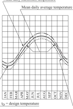
B.2.4.5 The design temperature tD is to be taken as the lowest mean daily average air temperature in the area of operation, see Fig. 2.2 The following definitions apply:
Mean: statistical mean over an observation period of at least 20 years Average: average during one day and night
Lowest: lowest during year
For seasonally restricted service the lowest expected value within the period of operation applies. (IACS UR S6.3)
JAN FEB MAR APR MA
Y
JUN JUL AUG SEP OCT NOV DEC Mean daily average temperature Mean daily maximum temperature
Mean daily minimum temperature tD = design temperature
Fig. 2.1 Commonly used definitions of temperatures B.3 Structural members which are stressed in direction of their thickness
In case of high local stresses in the thickness direction, e.g. due to shrinkage stresses in single bevel or double bevel T-joints with a large volume of weld metal, steels with guaranteed material properties in the thickness direction according to the GL Rules for Steel and Iron Materials (II-1-2), Section 1, I. are to be used.
C
Forged Steel and Cast Steel
Forged steel and cast steel for stem, stern frame, rudder post as well as other structural components, which are subject of this Rule, are to comply with the GL Rules for Metallic Materials (II-1). The tensile strength of forged steel and of cast steel is not to be less than 400 N / mm2. While selecting forged steel and cast steel toughness requirements and weldability are to be considered beside the strength proper-ties.
D Aluminium
Alloys
D.1 Where aluminium alloys, suitable for seawater, as specified in the GL Rules for Materials and Welding (II), are used for the construction of superstructures, deckhouses, hatchway covers and similar parts, the conversion from steel to aluminium scantlings is to be carried out by using the material factor:
A p0,2 m 635 k R R
For welded connections the respective values in welded condition are to be taken. Where these figures are not available, the respective values for the soft-annealed condition are to be used.
Method of conversion:
A St A
W W k for the section modulus
A ST A
t t k for the plate thickness
D.2 The smaller Young's modulus E is to be taken into account when determining the buckling strength of structural elements subjected to compression. This is to be applied accordingly to structural elements for which maximum allowable deflections have to be adhered to.
D.3 The conversion of the scantlings of the main hull structural elements from steel into aluminium alloy is to be specially considered taking into account the smaller Young's modulus E, as compared with steel, and the fatigue strength aspects, specifically those of the welded connections.
E Austenitic
Steels
Where austenitic steels are applied having a ratio Rp0.2 / Rm≤ 0.5, after special approval the 1 % proof stress Rp1.0 may be used for scantling purposes instead of the 0.2 % proof stress Rp0.2.
Table 2.10 Material classes and grades for structures exposed to low temperatures
Structural member category
Material class Within 0.4 L
amidships Outside amidships 0.4 L Secondary:
I I Deck plating exposed to weather, in general
Side plating above BWL5
Transverse bulkheads above BWL5
Primary:
II I Strength deck plating1
Continuous longitudinal members above strength deck, ex-cluding longitudinal hatch coamings
Longitudinal bulkhead above BWL5
Special:
III II Sheer strake at strength deck2
Stringer plate in strength deck2 Deck strake at longitudinal bulkhead Continuous longitudinal hatch coamings4
1 Plating at corners of large hatch openings to be specially considered. Class III or grade E / EH to be applied in positions where high local stresses may occur.
2 Not to be less than grade E / EH within 0.4 L amidships in ships with length exceeding 250 m. 3 Intentionally left blank
4 Not to be less than grade D / DH 5 BWL = ballast water line.
Table 2.11 Material grade requirements for classes I, II and III at low temperature Class I Plate thickness [mm] tD tD tD tD – 20 C to – 25 °C – 26 °Cto – 35 °C – 36 °C to – 45 °C – 46 °C to – 55 °C normal
strength strength higher strengthnormal strengthhigher strengthnormal strength higher strength normal strengthhigher
t ≤10 A AH B AH D DH D DH 10 < t ≤15 B AH D DH D DH D DH 15 < t ≤20 B AH D DH D DH E EH 20 < t ≤25 D DH D DH D DH E EH 25 < t ≤30 D DH D DH E EH E EH 30 < t ≤35 D DH D DH E EH E EH 35 < t ≤45 D DH E EH E EH FH 45 < t ≤50 E EH E EH FH FH Class II Plate thickness [mm] tD tD tD tD – 20 C to – 25 °C – 26 °Cto – 35 °C – 36 °C to – 45 °C – 46 °C to – 55 °C normal strength higher strength normal strength higher strength normal strength higher strength normal strength higher strength t ≤10 B AH D DH D DH E EH 10 < t ≤20 D DH D DH E EH E EH 20 < t ≤30 D DH E EH E EH FH 30 < t ≤40 E EH E EH FH FH 40 < t ≤45 E EH FH FH 45 < t ≤50 E EH FH FH Class III Plate thickness [mm] tD tD tD tD – 20 C to – 25 °C – 26 °Cto – 35 °C – 36 °C to – 45 °C – 46 °C to – 55 °C normal
strength strength higher strengthnormal strengthhigher strengthnormal strength higher strength normal strengthhigher
t ≤10 D DH D DH E EH E EH 10 < t ≤20 D DH E EH E EH FH 20 < t ≤25 E EH E EH FH FH 25 < t ≤30 E EH E EH FH FH 30 < t ≤35 E EH FH FH 35 < t ≤40 E EH FH FH 40 < t ≤50 FH FH (IACS UR S6 Table 9)
Section 3
Design Principles
A General ... 3-1 B Structural Members ... 3-2 C Effective Breadth of Plating... 3-11 D Proof of Buckling Strength ... 3-12 E Structural Details ... 3-25 F Evaluation of Notch Stress... 3-29 G Corrosion Additions ... 3-31 H Testing of Watertight and Weathertight Compartments ... 3-32
A General
A.1 Application
This Section contains definitions and general design criteria for hull structural elements as well as indica-tions concerning structural details.
A.2 References
International conventions and codes
Paragraphs of this section are based on the following international convention(s) and/or code(s): IACS UR S11 Rev.7
At the end of each relevant paragraph, the corresponding paragraphs of the international convention(s) and/or code(s) are given in brackets.
A.3 Definitions Unsupported span
In general the unsupported span is the true length of stiffenings between their two supporting structural members or else their length including end attachments (brackets).
In case of corrugated bulkhead elements the unsupported span is their length between bottom or deck and their length between vertical or horizontal girders. Where corrugated bulkhead elements are con-nected to box type elements of comparatively low rigidity, their depth is to be included into the span unless otherwise proved by calculations.
Frame spacings and spans
The frame spacings and spans are normally assumed to be measured in a vertical plane parallel to the centreline of the ship. However, if the ship's side deviates more than 10 ° from this plane, the frame dis-tances and spans are to be measured along the side of the ship.
Instead of the true length of curved frames the length of the chord between the supporting points can be selected.
Symbols
k : material factor according Section 2, A.2 W : section modulus [cm3] of smaller section
t : plate thickness [mm]
t' : required rule thickness excluding tK [mm] ta : "as built" plate thickness [mm]
tK : corrosion addition [mm] according to G tn : nominal plate thickness [mm]
n a K
t t t
A.4 Fatigue strength
Where a fatigue strength analysis is required or will be carried out for structures or structural details this is to be in accordance with the requirements of Section 20.
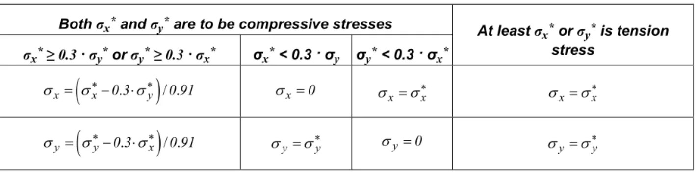
A.5 Permissible stresses and required sectional properties
In the following Sections permissible stresses have been stated in addition to the formulae for calculating the section moduli and cross sectional areas of webs of frames, beams, girders, stiffeners etc. and may be used when determining the scantlings of those elements by means of direct strength calculations.
B Structural
Members
B.1 Upper and lower hull flange
B.1.1 All continuous longitudinal structural members up to zo below the strength deck at side and up to zu above base line are considered to be the upper and lower hull flange respectively.
B.1.2 Where the upper and/or the lower hull flange are made from normal strength hull structural steel their vertical extent zo = zu equals 0.1 · H.
On ships with continuous longitudinal structural members above the strength deck a fictitious depth H' = eB + e'D is to be applied.
eB : distance [m] between neutral axis of the midship section and base line
e'D : distance [m] from neutral axis of hull section to fictitious top of deck section according to Section 5, E.1.1.1
B.1.3 The vertical extent z of the upper and lower hull flange respectively made from higher tensile steel of one quality is not to be less than determined by the following formula:
z e (1 n k)
e : distance of deck at side or of the base line from the neutral axis of the midship section. For ships with continuous longitudinal structural members above the strength deck, see Section 5, E.1.1.1
n : ratio of section moduli, defined as:
a W nW
W(a) : actual deck or bottom section modulus W : rule deck or bottom section modulus
Where two different steel grades are used it has to be observed that at no point the stresses are higher than the permissible stresses according to Section 5, E.1.2.1.
B.2 Plating B.2.1 Tapering
In general in case of different thicknesses of adjacent plates the plate thicknesses are to be tapered gradually.
B.2.2 Plates subjected to lateral pressure
The formulae for plate panels subjected to lateral pressure as given in the following Sections are based on the assumption of an uncurved plate panel having an aspect ratio b / a ≥ 2.24.
For curved plate panels and/or plate panels having aspect ratios smaller than b / a 2.24, the thickness may be reduced as follows:
1 2 K t C a p k f f t [mm]
C : constant, e.g. C = 1.1 for tank plating
p : applicable design load
f1 : curvature factor, defined as:
1 a
f 1
2 r
with f10.75
f2 : aspect ratio factor, defined as: 2 2 a f 1.1 0.5 b with f21.0
a : smaller breadth of plate panel b : larger breadth of plate panel
r : radius of curvature
The above does not apply to plate panels subjected to ice pressure according to Section 15 and to longi-tudinally framed shell plating according to Section 6.
B.2.3 Plates at sniped ends of stiffeners
If a stiffener with a sniped end is attached to plate, the minimum thickness t of the plate is to be deter-mined by the following formula:
e H p a ( 0.5 a) t c [mm] R
c : coefficient , defined as:
c 15.8 for watertight bulkheads and for tank bulkheads
when loaded by pT2 as defined in Section 4, D.1.2
c 19.6 otherwise
p : design load [kN / m2]
a : spacing of stiffeners [m]
: unsupported span of stiffener [m]
B.3 Stiffener and primary supporting members B.3.1 Required sectional properties
B.3.1.1 The required section moduli and web areas are related on principle to an axis which is parallel to the connected plating.
B.3.1.2 For profiles usual in the trade and connected vertically to the plating in general the appertain-ing sectional properties are given in tables.
B.3.1.3 Where webs of stiffeners and girders are not fitted vertically to the plating (e.g. frames on the shell in the flaring fore body) the sectional properties (moment of inertia, section modulus and shear area) have to be determined for an axis which is parallel to the plating.
B.3.1.4 For bulb profiles and flat bars the section modulus of the inclined profile including plating can be calculated simply by multiplying the corresponding value for the vertically arranged profile by sinα where α is the smaller angle between web and attached plating.
Note
For bulb profiles and flat bars α in general needs only be taken into account where α is less than 75 °.
B.3.1.5 Furthermore, with asymmetric profiles where additional stresses occur according to B.3.7 the required section modulus is to be increased by the factor ksp depending on the type of profile, see B.3.7.
B.3.2 Stiffeners loaded by lateral pressure
If stiffened plate panels are loaded by lateral pressure, the load is transmitted partly direct and partly by the stiffeners to the girders. The factor ma takes into account the corresponding load distribution on stiff-eners and is to be determined by the following formula:
2 a m 0.204 4 a a with 1 a B.3.3 Unsupported span
B.3.3.1 Stiffeners and frames
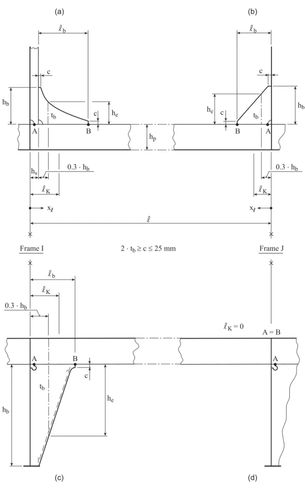
The factor mk1 takes into account shortening of the unsupported span due to brackets and heel stiffen-ers and is to be determined by the following formula:
KI KJ k1 3 m 1 10
KI, KJ : effective supporting length [mm] due to heel stiffeners and brackets at frame I and J (see Fig. 3.1) KI KJ s b b s 1 1 , min h 0.3 h ; h c
c1 : coefficient [1 / mm], defined as:
2 b b 1 2 b b e 1 1 c ( 0.3 h ) 1 c 0.3 h h for b 0.3 h b 1 1 0 c for b 0.3 h b
hs : height of the heel stiffener [mm] (see also Fig. 3.1) b, hb : dimensions of the brackets [mm] (see also Fig. 3.1)
he : height of bracket [mm] in the distance of hs + 0.3 · hb of frame I or J respectively (see also Fig. 3.1)
c1 : coefficient, defined as: 2
c 3 general
2
If no heel stiffeners or brackets are arranged the respective values are to be taken as (hs, hb, 1 / c1) = 0 (see Fig. 3.1). B h p he hb tb c c hs 0.3 × hb b K Frame I 0.3 × hb K 2 × tb ³ c £ 25 mm Frame J b c he c hb B tb A = B K= 0 0.3 × hb K b B tb hb he c (a) (b) (c) (d) x x A A A A
B.3.3.2 Transverses and girders
The factor mk2 takes into account shortening of the unsupported span of transverses and girders due to end attachments and is to be determined by the following formula:
k2 a b m
4
a, b : length’s according to Fig. 3.2, depending on the type of end attachment
In special cases, the rigidity of the adjoining girders is to be taken into account when determining the span of girder. c a b b c a b' b a =a'b' a'
Fig. 3.2 End attachment of transverses and girders
B.3.3.3 Main frames
The factor mk3 takes into account shortening of the unsupported length of main frames due to end at-tachments and is to be determined by the following formula:
Ku Ko k3 m 1.0 0.4 with cus30.6
Ku, Ko : length of lower/upper bracket connection of main frames within the length [m], see Fig. 3.3
Ko
Ku
Fig. 3.3 End attachment of main frames B.3.4 Curved frames
The capacity of a frame subjected to lateral pressure depends among others parameters on its curvature, if excisting.
The factor mc to takes into account the influnece of a curvature and is to be determined by the following formula:
c s m 1.0 2
with cr 0.75
s : maximum height of curve [m]
B.3.5 End attachments B.3.5.1 Definitions
For determining scantlings of beams, stiffeners and girders the terms "constraint" and "simple support" will be used.
"Constraint" will be assumed where the stiffeners are rigidly connected to other members by means of brackets or are running throughout over supporting girders.
"Simple support" will be assumed where the stiffener ends are sniped or the stiffeners are connected to plating only, see also B.2.3.
B.3.5.2 Brackets
B.3.5.2.1 For the scantlings of brackets the required section modulus of the section is decisive. Where sections of different section moduli are connected to each other, the scantlings of the brackets are gener-ally governed by the smaller section.
B.3.5.2.2 The thickness t of brackets is to be determined by the following formula:
3 K
1 W
t c t [mm]
k
with 5.0 + tk≤ t ≤web thickness of smaller
sec-tion c : coefficient [1 / mm], defined as:
c 1.20 for non-flanged brackets
c 0.95 for flanged brackets
k1 : material factor k for the section, according to Section 2, A.2 tK : corrosion addition [mm] according to G
For minimum thicknesses in tanks see Section 12, B.1.3.
B.3.5.2.3 The arm length b of brackets is to be determined by the following formula:
3 b 2 t 1 W 46.2 k c [mm] k with bb,min
b,min : minimum arm length [mm], defined as: b,min 100 mm
k1 : material factor k for the section, according to Section 2, A.2 k2 : material factor k for the bracket, according to Section 2, A.2 ct : coefficient, defined as:
t a t c t
ta : "as built" thickness of bracket [mm], with: ta≥ t according to B.3.5.2.2
Note
For deviating arm length the thickness of brackets is to be estimated by direct calculations considering sufficient safety against buckling.
B.3.5.2.4 The throat thickness a of the welded connection is to be determined according to Section 19, C.2.7.
B.3.5.2.5 Where flanged brackets are used the width of flange is to be determined by the following for-mula:
W
b 40 [mm]
30
with 50 mm b 90 mm
B.3.6 Longitudinals and longitudinal beams in way of curved plates
In way of curved plates (e.g. in the bilge area) the requirements regarding scantlings of longitudinals and longitudinal beams may be reduced by the following factor cR:
R 4 2 a 1 c t 1 0.006 I R a
t : thickness [mm] of shell plating
Ia : moment of inertia [cm4] of the longitudinal frame, including effective breadth R : bending radius [m] of the plate
In way of straight plates the factor cR is to be set to zero.
B.3.7 Asymmetric sections / profiles
B.3.7.1 Additional stresses for fatigue strength analysis
The additional stress σh occurring in asymmetric sections may be determined by the following formula:
2 2
2 f f h 1 2 y z Q t b b [N / mm ] c W W Q : load [kN] on section parallel to its web within the unsupported span f, defined as: f
Q p a [kN] in case of uniformly distributed load p [kN / m2]
f : unsupported span [m] of flange
tf, b1, b2 : flange dimensions [mm] as shown in Fig. 3.4, with:
1 2
y z b2 z y tf h w 2 hw sh b1
Fig. 3.4 Asymmetric profiles
c : factor depending on kind of load, stiffness of the section's web and length and kind of sup-port of the profile.
For profiles clamped at both ends and constant area load c = 80 can be taken for approxima-tion. A precise calculation may be required, e.g. for longitudinal frames.
Wy : section modulus [cm3] of section related to the y-y axis including the effective breadth of plating
Wz : section modulus [cm3] of the partial section consisting of flange and half of web area related to the z-z axis, (bulb sections may be converted into a similar L-section)
This additional stress σh is to be added directly to other stresses such as those resulting from local and hull girder bending.
B.3.7.2 Correction of section modulus
In case of asymmetric sections the required section modulus is to be multiplied with the factor ksp accord-ing to Table 3.1.
Table 3.1 Increase factor ksp
Type of Profile ksp
Flat bars and symmetric T-profiles 1.00
Bulb profiles 1.03
Asymmetric T-profiles with 2 1 b
0.5
b 1.05
Rolled angles (L-profiles) 1.15
B.3.8 Additional stresses due to local bending of stiffeners B.3.8.1 Additional stresses for fatigue strength analysis
For fatigue strength calculations according to Section 20, Table 20.1 bending stresses due to local stiff-ener bending and longitudinal normal stresses due to global hull girder bending are to be combined. Bending stresses at the points A and B (see Fig. 3.1) from local stiffener bending due to lateral loads p can be determined by the following formulae:
2 2
2 2 A k1 a h a 83 m m p [N/ mm ] W a for 0 x k with
2 2 2 k1 k1 a m m m 2 2 B cR A m [N/ mm ]1 for x hs bmk1 : factor to take a shortened unsupported span into account according to B.3.3 ma : factor to take the load distribution into account according to B.3.2
p : design pressure [kN / m2]
h : additional stress occurring in asymmetric sections according to B.3.7.1 x : distance [mm] from transverse structure at I and J respectively, see Fig. 3.1
k : effective supporting length [mm] due to heel stiffeners and brackets according B.3.3.1 cR : factor to take curved plates (e.g. in the bilge area) inn way of longitudinals and longitudinal
beams into account, according to B.3.6
m1 : factor, defined as:
1 3 3
m 1 4 c 1 0.75 c
c3 : factor, defined as:
sI bI kI 3 3 k,1 h c m 10 for position B at I sJ bJ KJ 3 3 k,1 h c m 10 for position B at J
The stresses at point A is not to be less than the stresses in adjacent fields (aft of frame I and forward of frame J respectively).
B.3.8.2 Additional stresses in longitudinals between transverse bulkheads and side trans-verses
Where necessary, for longitudinals between transverse bulkheads and side transverses additional stress-es rstress-esulting from the deformation of the side transversstress-es are to be taken into account.
If no special verification of stresses due to web frame deformations is carried out, the following minimum values are to be considered for fatigue strength verification of side longitudinals:
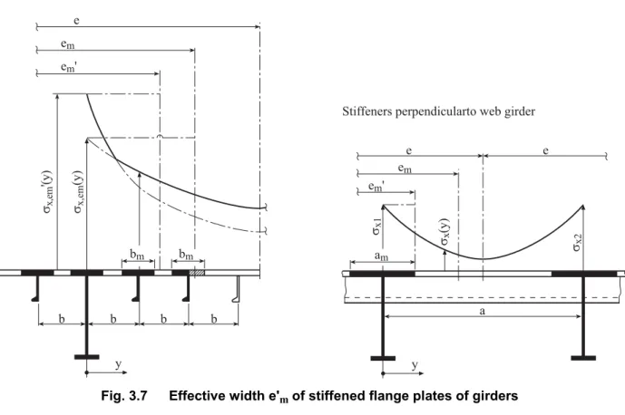
2 2 w R DF p p b h 0.1 C (1 C ) [N / mm ] DF
hw : web height [mm] of profile i (see Fig. 3.7)
b : sum of supporting lengths of heel stiffeners and brackets (see Fig. 3.1), defined as:
3b hsIlbIhsJlbJ 10 [m]
R : unsupported web frame length [m] (see Fig. 3.5) DF : height [m] of web frame (see Fig. 3.5)
Cp : weighting factor regarding location of the profile, defined as:
Ro R T p T (z z ) / C C 1 2 C
zRo : z-coordinate [m] of web frame outset above basis (see Fig. 3.5), zRoT CT : correction regarding location of the profile i to the water line, defined as:
T z
C 1.1
T
R DF ZRo Z i Fig. 3.5 Definitions B.4 Corrugated bulkhead elements
B.4.1 End attachment
Care is to be taken that the forces acting at the supports of corrugated bulkheads are properly transmitted into the adjacent structure by fitting structural elements such as carlings, girders or floors in line with the corrugations.
Note
Where carlings or similar elements cannot be fitted in line with the web strips of corrugated bulkhead el-ements, these web strips cannot be included into the section modulus at the support point for transmitting the moment of constraint.
Deviating from the formula stipulated in Section 11, F.3 the section modulus of a corrugated element is then to be determined by the following formula:
3W t b d t [cm ]
C
Effective Breadth of Plating
C.1 Frames and stiffeners
Generally, the spacing of frames and stiffeners may be taken as effective breadth of plating.
C.2 Girders
C.2.1 The effective breadth of plating em of frames and girders may be determined according to Ta-ble 3.2 considering the type of loading.
Special calculations may be required for determining the effective breadth of one-sided or non-symmetrical flanges.
In Table 3.2 following definitions are used:
e : width of plating supported, measured from centre to centre of the adjacent unsupported fields
em : effective breadth of plating, defined as: m m1
e e for girders which loaded by uniformly distributed
loads or else by not less than 6 equally spaced single loads.
m m2
e e for girders which are loaded by 3 or less single
loads.
: length between zero-points of bending moment curve, i.e. unsupported span in case of simp-ly supported girders and 0.6 x unsupported span in case of constraint of both ends of girder
C.2.2 The effective cross sectional area of plates is not to be less than the cross sectional area of the face plate.
Table 3.2 Effective breadth em of frames and girders
/ e 0 1 2 3 4 5 6 7 ≥ 8
em1 / e 0 0.36 0.64 0.82 0.91 0.96 0.98 1.00 1.00
em2 / e 0 0.20 0.37 0.52 0.65 0.75 0.84 0.89 0.90
Intermediate values may be obtained by direct interpolation.
C.2.3 The effective width of stiffeners and girders subjected to compressive stresses may be deter-mined according to D.3.2, but is in no case to be taken greater than the effective breadth determined by C.2.1.
C.3 Cantilevers
Where cantilevers are fitted at every frame, the effective breadth of plating may be taken as the frame spacing. Where cantilevers are fitted at a greater spacing the effective breadth of plating at the respective cross section may approximately be taken as the distance of the cross section from the point on which the load is acting, however, not greater than the spacing of the cantilevers.
D
Proof of Buckling Strength
D.1 Application
D.1.1 All structural members which are subjected to compressive and/or shear stresses are to be examined for sufficient resistance to buckling. For this purpose the design stresses according to Section 5, D.2 and the stresses due to local loads are to be considered.
D.1.2 For structural members contributing to the longitudinal strength see also Section 5, E.4.
D.2 Definitions
a : length [mm] of single or partial plate field b : breadth [mm] of single plate field
K : buckling factor according to Table 3.5 and Table 3.6
F1 : correction factor for boundary condition at the longitudinal stiffeners, defined as: 1
F 1.00 for stiffeners sniped at both ends
Guidance values where both endsare effectively connected toadjacent structures: 1
F 1.05 for flat bars
1
F 1.10 for bulb sections
1