Function Code 178
Data Acquisition
Analog Input/Loop
The data acquisition analog input/loop function code provides a way to import data from the data acquisition analog block (function code 177) on Symphony systems.
NOTE: If a module utilizes an imported analog value from the loop in several instances in its configuration, the function blocks that utilize that analog value must be connected to only one DAANG I/L block. You cannot import exception reports from the same (control network, node, module and block) address to more than one destination within a single module configuration.
Explanation
Specifications
S1 Source module address. This is the module bus address of the module containing the monitored DAANG block.
Outputs
Blk Type Description
N R Current value, quality/status N+1 R Next highest limit
N+2 R Next lowest limit N+3 R Extended status DA A N G I/L (178) N N + 1 N + 2 N + 3 N H L N L L E S T Specifications
Spec Tune Default Type Range Description S1 N 0 I 0 - 31 Source module address S2 N 0 I Note 1 Source block number S3 N 0 I 1 - 250 Source node address S4 N 0 I 1 - 250 Source loop number
S5 N 0 I Full Spare integer input
S6 N 0.000 R Full Spare real input S7 N 0 I 0 or 1 Spare boolean input
NOTES:
1. Maximum values are: 9,998 for the BRC-100, IMMFP11/12 31,998 for the HAC
S2 Source block number. This is the block number of the moni-tored DAANG block.
S3 Source HCU address. This is the HCU address where the mod-ule containing the monitored DAANG block resides.
S4 Source loop number. This is the loop number where the HCU containing the monitored DAANG block resides.
S5 through S7 Spare inputs.
Outputs
N Current value and quality/status: the current value, quality and status of the monitored DAANG block addressed by S1, S2, S3 and S4. Table 178-1 shows the status bits at this block address.
The test quality block (function code 31) can retrieve the qual-ity status bit. The qualqual-ity bit is bad when the communication status or the hardware failure status is bad.
The test alarm block (function code 69) can retrieve the alarm status bits. Setting S2 (function code 69) to zero tests the high and low alarms. Setting S2 (function code 69) to one tests the alarm level.
N+1 Next highest limit. This value is the next highest value limit that results in alarm activity by the DAANG block (function code 177) being monitored.
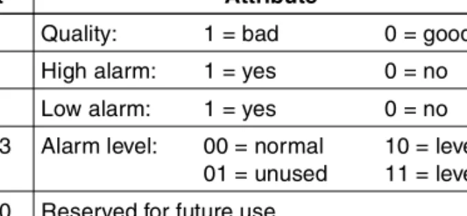
Table 178-1. Status Bits at Current Block Address
Bit Attribute
7 Quality: 1 = bad 0 = good 6 High alarm: 1 = yes 0 = no 5 Low alarm: 1 = yes 0 = no 4 - 3 Alarm level: 00 = normal 10 = level 2
01 = unused 11 = level 3 2 - 0 Reserved for future use
N+3 Extended status. The extended status converts into a real out-put as an integer with the bit map shown in Table 178-2.
The exception report received (bit 15) initializes to zero on entry to execute mode and sets upon the first exception report. The bit remains set until the module is reset or a mode change occurs. Refer to Figure 178-1 for an example of the module access to status.
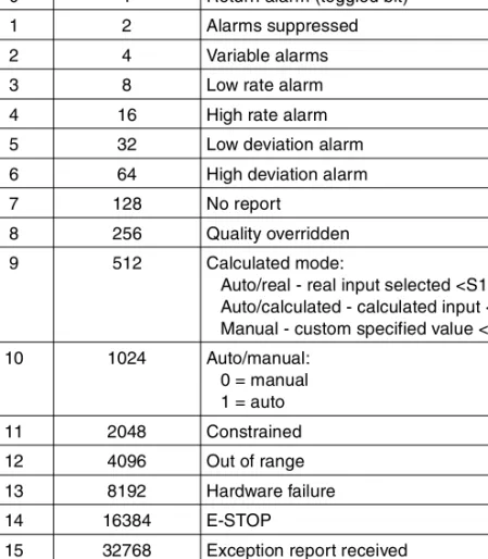
Table 178-2. Extended Status Bit Map
Bit Binary
Weighted Value Attribute 0 1 Return alarm (toggled bit)
1 2 Alarms suppressed
2 4 Variable alarms
3 8 Low rate alarm
4 16 High rate alarm
5 32 Low deviation alarm 6 64 High deviation alarm
7 128 No report
8 256 Quality overridden
9 512 Calculated mode:
Auto/real - real input selected <S10> Auto/calculated - calculated input <S12> Manual - custom specified value <S13>
10 1024 Auto/manual: 0 = manual 1 = auto 11 2048 Constrained 12 4096 Out of range 13 8192 Hardware failure 14 16384 E-STOP
15 32768 Exception report received
Applications
Assume that the monitored DAANG function code is (also shown in Table 178-3):
High constraint limit = 900 High 3 alarm limit = 800 High 2 alarm limit = 700
Figure 178-1. Module Access to Status
DA A N G I/L T S T Q T S TA LM T S TA LM R D E M U X R D E M U X S 1 S 1 S 1 S 2 S 3 S 4 G O O D /B A D Q UA L IT Y (1 7 8 ) N N + 1 N + 2 N + 3 (6 9 ) N N + 1 (6 9 ) N N + 1 (1 2 6 ) N N + 1 N + 2 N + 3 N + 4 N + 5 N + 6 N + 7 (1 2 6 ) N N + 1 N + 2 N + 3 N + 4 N + 5 N + 6 N + 7 T 01 8 75 A H IG H A L A R M L O W A L A R M L E V E L 2 A L A R M L E V E L 3 A L A R M T IM E IN A L A R M TO G G L E A L A R M S S U P P R E S S E D VA R IA B L E A L A R M S A C T IV E L O W R AT E A LA R M H IG H R AT E A L A R M L O W D E V IAT IO N A L A R M H IG H D E V IAT IO N A L A R M N O R E P O R T Q UA L IT Y OV E R R ID E C A L C U L AT E D VA LU E AU TO (1)/M A N UA L (0 ) C O N S T R A IN E D O U T O F R A N G E H A R DW A R E FA ILU R E E -S TO P R E S E RV E D (A LW AY S = 1 ) (3 1 ) N N H L N L L E S T H L H L 1 2 3 4 5 6 7 8 1 2 3 4 5 6 7 8
Low 3 alarm limit = 200 Low constraint limit = 100
NOTE: Constraints active, multilevel alarming and auto mode.
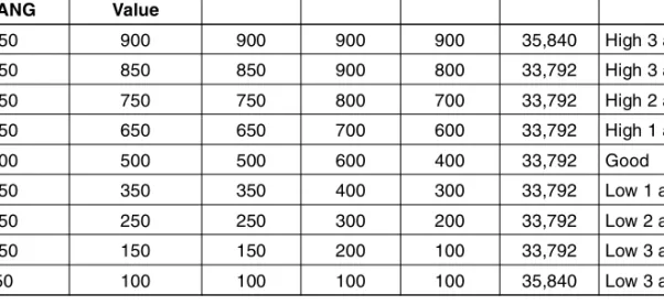
Table 178-3. Example DAANG Settings
Monitored Real Value Input of DAANG Referenced DAANGs Reported Value
DAANG I/L Outputs
Output N Quality N N+1 N+2 N+3 950 900 900 900 900 35,840 High 3 alarm 850 850 850 900 800 33,792 High 3 alarm 750 750 750 800 700 33,792 High 2 alarm 650 650 650 700 600 33,792 High 1 alarm 500 500 500 600 400 33,792 Good 350 350 350 400 300 33,792 Low 1 alarm 250 250 250 300 200 33,792 Low 2 alarm 150 150 150 200 100 33,792 Low 3 alarm 50 100 100 100 100 35,840 Low 3 alarm NOTES:
1. Output N+3 = 33,792 (32,768 + 1024). Exception report received since module startup and DAANG is monitoring the real input.
2. Output N+3 = 35,840 (32,768 + 2048 + 1024). Exception report received since module startup, constrained input, and DAANG is monitoring the real input.