NASA/TM—2019–220155
Program Management for Concurrent
University Satellite Programs, Including
Propellant Feed System Design Elements
Shannah Nichole WithrowAmes Research Center, Moffett Field, California
Click here: Press F1 key (Windows) or Help key (Mac) for help
May 2019
NASA STI Program ... in Profile
Since its founding, NASA has been dedicatedto the advancement of aeronautics and space science. The NASA scientific and technical information (STI) program plays a key part in helping NASA maintain this important role.
The NASA STI program operates under the auspices of the Agency Chief Information Officer. It collects, organizes, provides for archiving, and disseminates NASA’s STI. The NASA STI program provides access to the NTRS Registered and its public interface, the NASA Technical Reports Server, thus providing one of the largest collections of aeronautical and space science STI in the world. Results are published in both non-NASA channels and by non-NASA in the non-NASA STI Report Series, which includes the following report types:
• TECHNICAL PUBLICATION. Reports of completed research or a major significant phase of research that present the results of NASA Programs and include extensive data or theoretical analysis. Includes compilations of significant scientific and technical data and information deemed to be of continuing reference value. NASA counterpart of peer-reviewed formal professional papers but has less stringent limitations on manuscript length and extent of graphic presentations.
• TECHNICAL MEMORANDUM.
Scientific and technical findings that are preliminary or of specialized interest, e.g., quick release reports, working papers, and bibliographies that contain minimal annotation. Does not contain extensive analysis.
• CONTRACTOR REPORT. Scientific and technical findings by NASA-sponsored contractors and grantees.
• CONFERENCE PUBLICATION. Collected papers from scientific and technical conferences, symposia,
seminars, or other meetings sponsored or co-sponsored by NASA.
• SPECIAL PUBLICATION. Scientific, technical, or historical information from NASA programs, projects, and missions, often concerned with subjects having substantial public interest.
• TECHNICAL TRANSLATION. English-language translations of foreign scientific and technical material
pertinent to NASA’s mission.
Specialized services also include organizing and publishing research results, distributing specialized research announcements and feeds, providing information desk and personal search support, and enabling data exchange services.
For more information about the NASA STI program, see the following:
• Access the NASA STI program home page at http://www.sti.nasa.gov
• E-mail your question to [email protected]
• Phone the NASA STI Information Desk at 757-864-9658
• Write to:
NASA STI Information Desk Mail Stop 148
NASA Langley Research Center Hampton, VA 23681-2199
NASA/TM—2019–220155
Program Management for Concurrent
University Satellite Programs, Including
Propellant Feed System Design Elements
Shannah Nichole WithrowAmes Research Center, Moffett Field, California
National Aeronautics and Space Administration Ames Research Center
ACKNOWLEDGMENTS
My sincere thanks to my advisor, Dr. Pernicka, for his encouragement and mentorship throughout my undergraduate and graduate career. I would like to thank Dr. Rovey and Dr. Berg for their contribution of the multi-mode thruster payload to the APEX and M3 missions, and my thesis committee members, Dr. Long and Dr. Meeks for their feedback and time. I would also like to acknowledge the financial support from the Missouri Space Grant Consortium, Academy of Mechanical and Aerospace Engineers, and NASA Ames Research Center’s education program.
Thank you to the Missouri S&T Aerospace Plasma Laboratory (Alex Mundahl, Mitch Wainwright, and Andrew Taylor). I am grateful to the APEX Chief Engineers, Kyle Segobiano and Corey Dodd, for their partnership and technical guidance, Zack Fizell for his CAD support, Alex Mundahl for contributing the pressurant tank sizing code, and Matt Klosterman for his STK contributions. The contributions and support of all of the M3 and APEX team members have made both of the satellites possible, as well as this report.
Available from:
NASA STI Support Services National Technical Information Service
Mail Stop 148 5301 Shawnee Road
NASA Langley Research Center Alexandria, VA 22312
Hampton, VA 23681-2199 [email protected]
757-864-9658 703-605-6000
This report is also available in electronic form at http://ntrs.nasa.gov/
TABLE OF CONTENTS
LIST OF ILLUSTRATIONS ... vi
LIST OF TABLES ... vii
NOMENCLATURE ... viii
SUMMARY ...1
1. INTRODUCTION ...2
1.1. M-SAT MULTI-MODE MICROPROPULSION MISSIONS ...3
1.1.1 Multi-Mode Micropropulsion Mission (M3) ...4
1.1.2 Advanced Propulsion EXperiment (APEX) ...4
1.2. AUTHOR’S INVOLVEMENT ...5
2. LITERATURE REVIEW ...6
2.1. UNIVERSITY NANOSATELLITE PROGRAM ...6
2.1.1 University Nanosatellite Program 4 at Missouri S&T ...6
2.1.2 Nanosatellite 4 to Nanosatellite 10 ...6
2.2. MULTI-MODE (CHEMICAL AND ELECTRIC) PROPULSION FOR SMALL SATELLITES ...8
2.2.1. Electric Propulsion (EP) Overview ...8
2.2.2. Chemical Propulsion Overview ...9
2.2.3. Systems With Flight Heritage to Date ...9
2.2.4. Larger Satellites With Dual Propulsion Systems ...10
2.2.5. Recent Small Satellite Propulsion Developments ...11
2.2.6. Missouri S&T Multi-Mode Thruster ...13
3. APEX AND M3 MISSION DESCRIPTION ...14
3.1. MULTI-MODE THRUSTER...14
3.2. SATELLITE BUS ...16
3.2.1. M3...16
3.2.2. APEX ...17
3.2.3. Feed System Components ...17
3.2.4. Feed System Layout ...25
3.3. VALIDATING THRUSTER PERFORMANCE ...27
TABLE OF CONTENTS (cont.)
3.5. RELAXING STUDENT CONSTRAINTS ...28
3.5.1. Component Changes ...28
3.5.2. Mass and Volume Savings ...30
4. PROPELLANT PRESSURIZATION PROOF OF CONCEPT ...31
4.1. TEST SETUP ...31
4.2. SYSTEM VALIDATION (TESTING) ...32
4.3. RESULTS ...32
4.3.1. Mass Loss ...32
4.3.2. Future Work—Mass Loss ...35
4.3.3. Pressure Loss ...35
4.3.4. Future Work: Expanding Pressure Loss to Entire System ...38
4.3.5. Minimum Operating Pressure ...38
4.3.6. Component Testing ...39
4.3.7. Next Steps—Testing ...40
4.3.8. Risk Analysis ...40
5. FEED SYSTEM LESSONS LEARNED AND PROPOSED APEX IMPROVEMENTS ...41
5.1. LESSONS LEARNED...41 5.1.1. Hardware Selection ...41 5.1.2. Materials ...42 5.1.3. Student Constraints ...42 5.1.4. Size...42 5.1.5. Hardware Training ...42
5.1.6. Diagnosing the Problem: Hardware/Software ...43
5.2. FEED SYSTEM IMPROVEMENTS ...44
5.2.1. Pressure Regulation ...44
5.2.2. Inhibits ...45
5.2.3. More Risk Analysis ...45
5.2.4. Numeric and Analytic Analyses ...45
TABLE OF CONTENTS (cont.)
6. DELIVERING SATELLITES EFFICIENTLY AND ROUTINELY ...48
6.1. DIFFERENCES BETWEEN INDUSTRY AND UNIVERSITY SATELLITE DEVELOPMENT ...48
6.2. TRAINING ...49
6.2.1. Team Training...49
6.2.2. Leadership Training ...50
6.3. INCENTIVES FOR UNIVERSITY STUDENTS ...50
6.4. SATELLITE ASSEMBLY, INTEGRATION, AND TESTING (AIT) ...51
6.5. DOCUMENTATION MANAGEMENT AND REVIEWS...51
6.6. SCHEDULING ...53
6.6.1. “Working Backwards” ...53
6.6.2. Assigning Tasks Versus Managing Tasks ...53
6.6.3. Gantt Charts ...54
6.6.4. Network Diagrams ...55
6.6.5. Flexibility ...56
7. CONCURRENT PROGRAMS ...57
7.1. ONE PROJECT VERSUS MULTIPLE PROJECTS ...57
7.1.1. Resources/Personnel ...57 7.1.2. Learning ...59 7.1.3. Reputation ...60 7.1.4. Schedule ...60 7.1.5. Summary ...60 REFERENCES ...62
APPENDIX A. STATE OF FLOW IN EXPERIMENTAL FEED SYSTEM PRESSURIZATION SETUP ...65
APPENDIX B. MATLAB CODES USED IN DESIGN AND TESTING ...67
LIST OF ILLUSTRATIONS
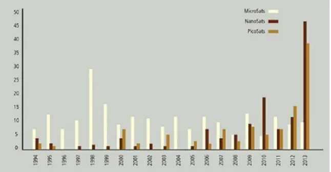
Figure 1.1. Satellite mission growth 1994–2013. ...2
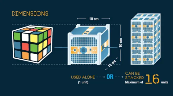
Figure 1.2 CubeSat dimensions ...3
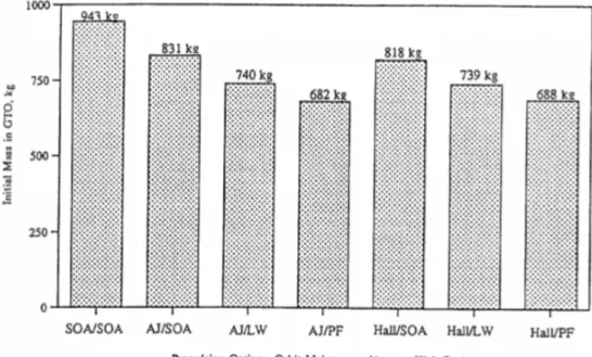
Figure 2.1. TACSAT mass with various propulsion systems ...10
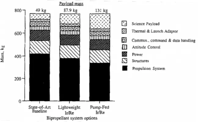
Figure 2.2. MUADEE satellite mass decomposition. ...11
Figure 2.3. Busek’s AMAC thruster: TRL 5. ...12
Figure 2.4. Accion Systems’ TILE-V1 thruster: TRL 5. ...12
Figure 2.5. Volume comparison. ...13
Figure 3.1. Multi-mode thruster: a) side view, b) front view, and c) placement on 6U satellite bus...15
Figure 3.2. Propulsion feed system and thruster layout in APEX CubeSat. ...17
Figure 3.3. 300-cc custom tank designed by M-SAT team.. ...19
Figure 3.4. Piston head starting location. ...20
Figure 3.5. Piston head ending location ...20
Figure 3.6. A single Swagelok 50-cc sample cylinder. ...21
Figure 3.7. Lee Company’s IEP series solenoid valve. ...22
Figure 3.8. Swagelok SS-CHS2-1 check valve. ...22
Figure 3.9. Mechanical pressure regulator internal view. ...23
Figure 3.10. Maxim integrated model DS18S20 pin layout. ...24
Figure 3.11. TE Connectivity’s miniature EPRB-1 pressure transducer dimensions ...25
Figure 3.12. APEX feed system layout. ...26
Figure 3.13. M3 feed system layout. ...27
Figure 3.14 Recommended feed system layout for industry application. ...29
Figure 3.15. Feed system incorporating student constraints. ...30
Figure 3.16. Minimalistic feed system. ...30
Figure 4.1. Pressurization proof-of-concept test setup. ...31
Figure 4.2. Mass remaining after pressurization—water. ...33
Figure 4.3. Mass remaining after pressurization—IPA. ...33
Figure 4.4. Mass remaining after pressurization—olive oil. ...34
LIST OF ILLUSTRATIONS (cont.)
Figure 4.6. Minimum operating vs. experimental pressure for feed system: olive oil. ...39
Figure 4.7. Simplified feed system diagram. ...40
Figure 5.1. MMS satellite layout. ...47
Figure 5.2. Rendezvous simulation in STK. ...47
Figure 6.1. Gantt chart of APEX for the first year. ...54
Figure 6.2. Network diagram block. ...55
Figure 6.3. Map of task blocks. ...55
Figure 6.4. Network diagram of the propulsion subsystem development in industry environment. ...56
LIST OF TABLES Table 3.1. Feed System Constraints ...18
Table 5.1. Propellant Usage to Rendezvous ...47
NOMENCLATURE Symbol Description Δ Change ρ Density µ Viscosity v Specific Volume
Program Management for Concurrent University
Satellite Programs, Including Propellant Feed
System Design Elements
Shannah Nichole Withrow*Ames Research Center
SUMMARY
Propulsion options for CubeSats are limited but are necessary for the CubeSat industry to continue future growth. Challenges to CubeSat propulsion include volume/mass constraints, availability of sufficiently small and certified hardware, secondary payload status, and power requirements. A multi-mode (chemical and electric) thruster was developed at the Missouri University of Science and Technology to enable CubeSat propulsion missions. Two satellite buses, a 3U and 6U, are under development to demonstrate the capability of the multi-mode thruster. Two key challenges related to these missions are the development of the feed system to support the thruster and management of the two bus programs’ personnel, resources, timelines, and budgets.
The feed system was designed to support the unique needs of the thruster, within the constraints and budget of a student-designed propulsion system, while minimizing risk as a secondary payload. This resulted in the development of a unique method to pressurize propellant stored in the feed system tubing. Within the expected operating pressure range, the method was experimentally shown to provide sufficient pressure and propellant volume to the thruster to meet mission success criteria.
The 3U and 6U CubeSat buses were designed concurrently with complimentary payloads, hardware, objectives, and team structures, and required careful management of resources between the two teams. With proper management, the two programs have been able to support one another through collaboration. Lessons learned include experience with design, testing, and assembly of hardware, team training/mentoring and motivation, improved documentation practices, and risk management.
*
Presented to the faculty of the Graduate School of the Missouri University of Science and Technology in partial fulfillment of the requirements for the degree Master of Science in Aerospace Engineering, 2019. Approved by
1. INTRODUCTION
Small satellite (smallsat) capabilities are developing rapidly and have the potential to change the space industry by increasing launch opportunities through reduced cost and more efficient use of launch vehicle payload space. Figure 1.1 shows the dramatic increase in the number of small satellite missions over the last 20 years. According to NASA’s Small Satellite Missions program, “Through technological innovation, small satellites enable entirely new architectures for a wide range of activities in space with the potential for exponential jumps in transformative science.”1 Steve Jurczyk, associate administrator for NASA’s Space Technology Mission Directorate, cites small satellites as a “paradigm shift for NASA and the larger space community.”2 This class of satellite has opened the testing ground of space to organizations, such as universities, not previously capable of supporting larger, more traditional spacecraft. CubeSats are popular among less traditional investigators. CubeSats are defined by their volume, which is composed of 10- x 10- x 10-cm “cubes” each known as units or “Us” (as illustrated in Fig. 1.2). Common total volumes of CubeSats are 1, 3, 6, or 12 Us. The standardization of these structures allows for simplified launch vehicle integration. Additionally, vendors are able to mass produce instrumentation and other necessary materials for this class in bulk, mitigating expenses associated with custom hardware for frequently used components.
However, satellites in this size category also have inherent challenges. Within the small satellite community, these challenges are frequently referred to as SWaP (size, weight, and power) as mass/volume and power are often the limiting factors of a design.
Figure 1.2. CubeSat dimensions.4
In 2001, Dr. Henry Pernicka founded the Missouri S&T Satellite Research Team (M-SAT) at the Missouri University of Science and Technology. The team’s first pair of satellites, Missouri Rolla and Missouri Rolla Second Satellite (MR and MRS SAT), were developed as a stereoscopic imaging demonstration mission using an innovative cold gas thruster design. MRS SAT functions as a non-cooperative object, while MR SAT contains the imaging system and cold gas thrusters. In 2015, MR and MRS SAT won first place in the Air Force Research Lab’s (AFRL’s) University Nanosatellite 8 Program, receiving a launch opportunity. Shortly after, M-SAT, in collaboration with Missouri S&T Aerospace Plasma (AP) Lab, submitted a proposal to AFRL’s University Nanosatellite 9 competition to develop a 6U multi-mode thruster technology demonstration mission. Additionally, the team submitted a proposal for a 3U version of the multi-mode thruster to NASA’s Undergraduate Student Instrumentation Project (USIP) to address and increase the Technology Readiness Level (TRL) of some of the more challenging aspects of the 6U demonstration. Both proposals were accepted, and work on these satellites is ongoing.
1.1. M-SAT MULTI-MODE MICROPROPULSION MISSIONS
Two micropropulsion satellite missions were chosen as an area of focus by the M-SAT team because they meet a current industry need. While the emergence of the CubeSat has enabled numerous space missions for relatively low cost and a rapid development timeline unachievable with larger satellite systems, the capability of these CubeSats has been limited by the lack of propulsive capability, particularly where multiple types of propulsion are needed. The 2015 NASA Small Spacecraft Technology State-of-the-Art report states, “As propulsion technology matures, more small spacecraft missions will incorporate propulsion systems on board allowing
for more complex mission architectures.”5 Additionally, the Air Force Technology Horizons report lists “Fractionated, Composable, Survivable, Autonomous Systems” as a technology grand challenge, and specifically calls out, “Rapidly Composable Satellite Systems: Satellites that can be assembled, tested, and launched within days of operational requirement, based on a plug-and-play/open-architecture approach using standards for self-describing components within a discoverable and autoconfiguring system”10 as a major focus. The need for propulsion systems for smallsats is becoming more urgent as the demand for these spacecrafts and their missions expand and diversify. Khary Parker points out in NASA Goddard’s “2017 State-of-the Art for Small Satellite Propulsion Systems” presentation, “[CubeSat] uses and capabilities are growing to the point where a propulsion system is required... Current state-of-the-art for smallsat propulsion systems is rapidly evolving. However, their technology readiness level (TRL) is still relatively low.”5 While CubeSat technology has rapidly developed, propulsion system development lags behind. Dr. Polzin from NASA Marshall Space Flight Center commented that, “There are lots of systems being developed out there, but none of them have come out clearly on top yet.”6 Air and Space Magazine recently reported, “The consumer electronics industry has dramatically shrunk sensors and microcontrollers in the last decade, but propulsion has proven harder to miniaturize.”7 It is therefore necessary to develop and validate the performance of such a propulsion system that can be easily integrated into a CubeSat form factor. As evidenced by the reports cited above, propulsion system technology that expands CubeSat mission opportunities is relevant and desired in many areas of the space community.
The 3U M3 and 6U APEX seek to demonstrate a solution to this propulsive need. Students have developed a propellant feed system that integrates into both the 3U and 6U CubeSat form factor and is paired with a thruster operable in both catalytic chemical and electrospray electric modes.
1.1.1 Multi-Mode Micropropulsion Mission (M3)
M3 is intended to be a “stepping stone” to the APEX mission. M3 is unique in that the USIP program limits the participants to undergraduates with one graduate student exception (i.e., the author, who functions as a mentor to the team). M3 will contain a smaller volume of propellant, perform fewer burns, and operate at a lower pressure than APEX. While the thruster aboard M3 will be capable of operating in chemical mode, electric mode will be used exclusively. This mission scaling allows the feed system, propellant, and thruster design to be validated on-orbit while mitigating risk from a launch range safety perspective. M3 is expected to be delivered to NASA at the end of the spring 2019 semester with potential launch dates in early 2020.
1.1.2 Advanced Propulsion EXperiment (APEX)
Lessons learned from M3 will be applied to APEX, which began development under AFRL’s University Nanosatellite 9 (NS-9) competition and will continue with a potential launch opportunity under AFRL’s University Nanosatellite 10 (NS-10) competition. APEX was designed as a 6U to meet the SWaP challenges associated with operating the thruster at its full capacity in both catalytic chemical and electrospray electric modes.
1.2. AUTHOR’S INVOLVEMENT
The author has been significantly involved with the design and development of both satellites. In January 2016 the author was selected as the Program Manager (PM) for the APEX satellite and attended the University Nanosatellite 9 Program kick-off meeting in Albuquerque in January. In this capacity, the author represented the team as the primary presenter at all AFRL University Nanosatellite Program (UNP) reviews, performed PM appropriate tasks—such as piloting documentation efforts, selecting and training team leads, managing the team’s resources and schedule, and coordinating the design and testing process—and acted as the primary ambassador and advocate for the project. During this time, the APEX satellite was developed from concept to a functioning engineering design unit (EDU). After Phase A of ARFL’s UNP NS-9 competition was completed in January 2018, the author performed appropriate close-out tasks and transitioned the team into preparation for the NS-10 program. The author assisted the Principal Investigator (PI) in preparing the UNP NS-10 proposal, which was accepted in November 2018 as 1 of 10 entries to AFRL’s University Nanosat 10 competition. Additionally, the author served as the propulsion lead for the APEX satellite from the Preliminary Design Review (January 2017) to the close-out of the NS-9 program. During this time, the author was responsible for the EDU propulsion feed system design and assembly, component selection, risk analysis, testing a novel pressurization concept, and interface planning with the thruster team. The author served as a liaison between the Space Systems Engineering Laboratory (SSE Lab), responsible for the satellite bus development, and the Aerospace Plasma Lab, responsible for the payload (thruster) development.
Upon the M-SAT team’s acceptance into the NASA USIP program in fall 2016, the author was selected as the official graduate student mentor (though others donated time as unofficial mentors) and acted as a pseudo PI for the team. In this position the author mentored approximately 25 to 30 undergraduate students each semester through the process of designing, testing, building, integrating, and delivering a 3U CubeSat. The satellite is expected to undergo environmental testing within a year of the author’s master’s degree defense. The author trained and motivated team leadership, developed actionable items based on provided requirements, proofed all written deliverables, acted as a liaison between the students and collaborators, influenced design decisions, and designed the feed system. The author used lessons learned from APEX to expedite the timeline of the project and optimized the use of resources by encouraging collaboration between the APEX and M3 teams.
2.LITERATURE REVIEW
2.1. UNIVERSITY NANOSATELLITE PROGRAM
The University Nanosatellite Program9 (UNP) was founded in 1999 as a university-outreach program by the AFRL at Kirtland Air Force Base. UNP has fostered 5,000+ students from 36 universities in 19 years. UNP’s main objectives are education, technology, and university laboratory development. During the course of the program, students start with a mission concept and go through a series of reviews, ending the first phase in a competition with an opportunity to launch their satellite. Common challenges for student teams include resource limitations, learning curve, improper (overly ambitious) mission scoping, insufficiently defined Concept of Operations (CONOPs), and software development. These challenges can be addressed by rigorous planning and implementation of systems engineering concepts. Critical personnel roles for a successful mission include a visionary to motivate the work, a source to drive the team’s momentum, a verification role, and a manager to promote team cohesion. The timeline is often a high-risk element for universities. A delicate balance must be struck between causing overstress and allowing too much slip (time deviated from original schedule). Student-planned intermediate milestones between UNP mandated milestones can help maintain the proper pace.8
2.1.1 University Nanosatellite Program 4 at Missouri S&T
In 2007 a guide detailing the systems engineering aspects of small satellite development at the university level was authored by an M-SAT team member (Abbie Stewart) targeting an audience organizing such a project for the first time.9 The M-SAT team (then known as the UMR SAT
team) from 2004 to 2007 was used as a model along with participation in the UNP Nanosatellite-4 (NS-Nanosatellite-4) Competition. Some aspects of this report are a continuation of this guide, specifically regarding lessons learned. In this study, the M-SAT team from 2016–2018 is used as a model along with the participation in the UNP NS-9 and -10 competitions and the NASA USIP Project. Both documents describe the process of designing and building a satellite from the ground up. This includes developing requirements, developing a design from those requirements and provided standards, testing, mitigating challenges, hardware assembly, documentation and team management, and team member/knowledge retention.
2.1.2 Nanosatellite 4 to Nanosatellite 10
The team has maintained a similar organizational structure throughout the years. The team is led by a professor (Dr. Henry Pernicka) who serves as the PI. The professor provides technical mentorship, chooses the projects and research areas the team will pursue, oversees the budget, approves purchases (as required by the university), and provides advisory and intermediary support to the team as needed. Students fill the roles of PM and Chief Engineer (CE). These positions are usually filled by senior members of the team with prior project experience. The PM manages or organizes the personnel related tasks, pilots the documentation process, runs meetings, manages the schedule, and acts as the primary team advocate to investors. The CE is responsible for managing the technical aspects of the team. This involves attending subsystem meetings, managing interfacing between subsystems, approving hardware selections, and leading
learning efforts when team knowledge gaps are discovered. It is vital to team success that the students in these two positions communicate often and work together. A Resource Manager oversees team training and outreach events. The team is broken up into subsystems with a lead overseeing each technical area. These subsystems are based on the team structure developed during the NS-4 competition. Current subsystems for the NS-10 and USIP projects are Command and Data Handling, Communications, Guidance, Navigation, and Control (formerly two subsystems: Attitude Determination and Control and Orbit Determination and Control), Integration, Power, Propulsion, Structure, and Thermal. Payload development is overseen by the Missouri S&T Aerospace Plasma Lab, which has partnered with the M-SAT team for these missions. The Integration subsystem is unique to the M-SAT team in contrast to most other university teams. The Integration team manages interface control documents and assembly procedures and was created as a result of lessons learned early in the M-SAT program. This ensures that valuable time is not wasted in later stages because of subsystem “tunnel” mentality. Students choose which subsystems they want to participate in, but they may be asked to consider also participating in other areas, depending on current team needs. Leads are chosen for each subsystem, primarily from senior team members. However, students may also be recruited from outside the current team if a certain skill set is needed based on other student or faculty recommendation.
Stewart9 asserts it is essential to select a mission that is of interest to both the team and customer. Customer interest from government organizations can be determined by strategic objectives published by the sponsoring organization. For the APEX and M3 missions, this included the Air Force Technology Horizons Report10 and NASA’s 2015 Technology Area Breakdown.11 Relevant objectives include:
• “Rapidly Composable Satellite Systems: Satellites that can be assembled, tested, and launched within days of operational requirement, based on a plug-and-play/open-architecture approach...” (Section 2.27—Air Force Technology Horizons Report10).
• “Liquid storable chemical propulsion, micropropulsion, electric propulsion, propellant storage and transfer, and power systems to enable propulsive technologies” (NASA Technology Area Breakdown for in-space propulsion, 2.1.1, 2.1.7, 2.2.1, 2.4.1, and 2.4.511). Additionally, the Stewart thesis discusses the criticality of selecting an appropriate scope based on timeframe and budget.9 The NS-9 program included many design decisions that were significantly impacted by budget constraints. For example, creating a feed system that was adaptable to a plug-and-play type design, similar to the thruster, would have required qualification outside of the cost constraints, so it was not included in the scope. The M3 mission faced more schedule constraints. For example, the mission objectives had to be de-scoped to only include performance of electric mode, as the certification to transport and fly the chemical component of the propellant that enables high-thrust burns could not be completed in the given timeframe.
Also highlighted in the thesis is that conference presentations are an effective, attractive mechanism for students to improve technical writing and presentation skills. They provide feedback from industry on the project throughout its duration and can lead to potential partners with industry mentors that can aid in needed technical expertise and sometimes low-cost hardware. At such events, students also frequently receive monetary awards, internships, or job offers, enhancing their career paths.9
The guide also discusses the challenge of team turnover. While it seems that some aspects of team transition have become more structured between NS-4 and NS-10, such as lead transition and improved documentation of past work, the author concurs with the Stewart thesis that a standardized form for graduating members would further improve the turnover process.9 This form should include recently completed tasks and results, recommendations for next steps, overarching goals, physical location of relevant equipment, and who to contact with questions— at a minimum. It should continue to be emphasized to new members that questions are welcomed and encouraged. Additional program management aspects of the NS-9 and NS-10 programs are discussed in Sections 6 and 7.
2.2. MULTI-MODE (CHEMICAL AND ELECTRIC) PROPULSION FOR SMALL
SATELLITES
The following sections provide an overview of relevant current and past propulsion technology.
2.2.1. Electric Propulsion (EP) Overview
The first EP system was flight tested in the 1960s, however development was slowed by power limitations on spacecraft at the time and hesitancy to abandon conventional methods. EP systems are composed of the thruster structure, a power system including a power processing unit (PPU) to convert raw power to the form required by the thruster, and a propellant-feed system. According to Martinez-Sanchez and Pollard in the Journal of Propulsion and Power in 1998, “The common feature of all EP schemes is the addition of energy to the working fluid from some electrical source. This has been accomplished, however, in a large variety of physically different devices. Operation can be steady or pulsed; gas acceleration can be thermal, electrostatic, electromagnetic, or mixed; the propellant can be gas, a chemical monopropellant, or even a solid.”12 EP systems are known to be high specific impulse (Isp) and low thrust. Examples of EP
thrusters include resistojets, arcjets, Hall thrusters, ion engines, pulsed plasma thrusters, vacuum arc thrusters, electrothermal, electrospray, and magnetoplasmadynamic thrusters. Descriptions of these thruster types can be found in Martinez-Sanchez and Pollard12 and Lemmer.13 EP systems are commonly used for station keeping, orbit adjustment, attitude control, and other repositioning maneuvers. Electrospray EP systems are of special interest to this study. Electrospray systems feed propellant to an emitter with an electric field generated between the emitter tip and an opposing electrode. Surface tension and the electric field distort the propellant into a Taylor cone at the emitter tip, increasing the intensity of the electric field. Propulsion is created by emission of a droplet from the Taylor cone (colloid thruster) or ion emission (field emission electric propulsion i.e., FEEP).12,13
Some EP systems have achieved flight history on CubeSats. Nanospace CubeSat MEMS propulsion module on the Chinese CubeSat TW-1 was an electrothermal system used to deorbit in 2015.14 Vacuum arc thrusters (VATs), a type of pulsed thruster, have CubeSat flight heritage in the form of the Micro Cathode Arc Thruster (µCAT) designed by George Washington University. µCAT flew aboard the United States Naval Academy’s BRICSat-P15 and was used to detumble the spacecraft, although mission results are not publicly available. Another VAT was flown on the Illinois Observing Nanosatellite (ION) from the University of Illinois, but no data were collected because of launch vehicle failure.16 FEEP electrospray thrusters, known as Scalable ion Electrospray Propulsion Systems (SiEPS), were developed by the Massachusetts Institute of Technology (MIT) and were flown as part of Aerospace Corporation’s IMPACT mission in 2015 on the CubeSat AeroCube-8.17,18 Data from the mission were not publicly released. Busek Company developed the BIT-3, a miniature ion engine scheduled to fly on two deep space CubeSats in 2020.19,13
2.2.2. Chemical Propulsion Overview
Chemical propulsion systems function using the same concept as rockets and thrusters used on traditional, larger spacecraft. The chemical reaction between fuel and oxidizer creates energy by breaking molecular bonds and accelerating the by-product through a supersonic nozzle. Chemical propulsion includes monopropellants, bi-propellants, and solid rockets. To date, no chemical propulsion systems have been used on a CubeSat because of restrictions on stored energy in secondary payloads, though many have been developed in lab settings by companies such as Aerojet Rocketdyne, Busek, VACCO/ECAPS, Tethers Unlimited, Inc., and DSSP.13 Most of these thrusters range from 0.1 to 1 N, however, the DSSP design boasts 76 N capability.13 Hydrazine has traditionally been the propellant of choice for chemical propulsion, however, it is not ideal for CubeSats that tend to be designed as secondary payload with a “Do No Harm” mentality. Hydrazine is toxic and has the ability to auto-combust at room temperature and pressures. Some alternatives that have been considered include green monopropellants (HAN and AN-based), peroxide blends (in development), bi-propellants, solid propellants, and even water. Although each has their challenges, the most resources are being dedicated to green monopropellants at the time of writing.13
2.2.3. Systems With Flight Heritage to Date
In “Propulsion for CubeSats” Dr. Lemmer states, “To date, only two missions have featured propulsion systems as part of the technology demonstration. The IMPACT mission from the Aerospace Corporation launched several electrospray thrusters from Massachusetts Institute of Technology, and BricSAT-P from the United States Naval Academy had four micro-Cathode Arc Thrusters from George Washington University. Other than these two missions, propulsion on CubeSats has been used only for attitude control and reaction wheel desaturation via cold gas propulsion systems.”13
One noteworthy example of cold gas thruster application is the JPL MarCO mission, launched in early 2019 (after Lemmer’s article was released), which contained a Vacco Micro CubeSat Propulsion Systems (MiPs) unit, capable of one to five trajectory correction maneuvers.47 This was the first use of CubeSats for interplanetary missions. Through the APEX and M3 missions,
Missouri S&T intends to add two more satellites to the list of CubeSats with technology- demonstration-level propulsion systems, almost doubling the current number of similar missions with flight heritage.
2.2.4. Larger Satellites With Dual Propulsion Systems20
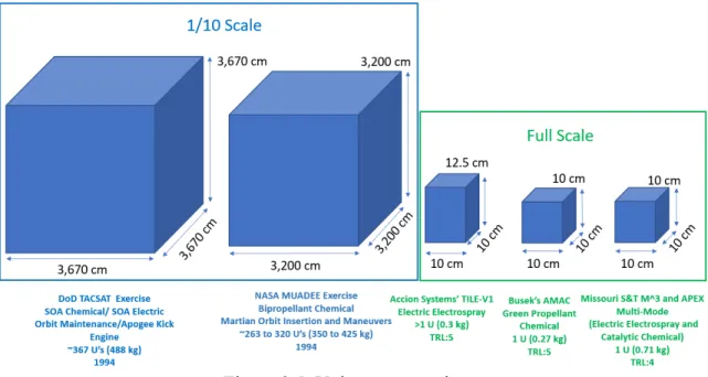
In 1994 “Small Satellite Propulsion Options,”21 a joint report between Nyma, Inc. and NASA Lewis, was released. This report discusses the potential benefits of adding propulsion systems available at the time to existing or planned spacecraft vehicles. One such mission, the Department of Defense (DoD) TACSAT, was a communication satellite. The report states, “Either hydrazine arcjets or xenon Hall thrusters could be added to the satellite to perform the north/south (NSSK) and east/west station keeping (EWSK) as well as to provide rapid on-orbit repositioning.”21 This type of system was one of the earliest suggested concepts of multiple modes of propulsion systems on a spacecraft. Figure 2.1 was included in the report (as Fig. 8) showing potential mass of the TACSAT with different chemical and electric thruster combinations. The total mass of the satellite with both propulsion systems ranged from 682 to 943 kg, with a primary concern being the size of the launch vehicle required to deliver such a mass to orbit. This is compared to a base system mass (no propulsion systems) of 455 kg.
Figure 2.2. MUADEE satellite mass decomposition.21
NASA’s proposed Mars Upper Atmosphere Dynamics, Energetics, and Evolution (MUADEE) satellite was also discussed in “Small Satellite Propulsion Options” joint report.21 MUADEE would contain a bipropellant chemical propulsion system and would be used to insert the spacecraft into the Martian atmosphere and perform smaller maneuvers. This mission was based on the design of the previous Venus pioneer spacecraft. Of the 800 kg allocated for the spacecraft, 350 to 425 kg would be needed for the propulsion system as shown in Figure 2.2.21
2.2.5. Recent Small Satellite Propulsion Developments
Technology has improved significantly, allowing modern day thrusters to be three orders of magnitude smaller than those described in 1994 with similar function. NASA’s “2017 State-of-the-Art for Small Satellite Propulsion Systems” document22 describes several thrusters currently in development within the CubeSat size envelope. Two examples are Busek’s AMAC (Advanced Monoprop Application for CubeSats) project (Fig. 2.3) and Accion Systems’ TILE-V1 project (Fig. 2.4). Busek’s AMAC project hosts a 1U “green” propellant thruster with a mass of 0.27 kg and a TRL of 5. Accion System’s TILE-V1 project hosts an electrospray electric propulsion system with a volume slightly larger than a 1U (10 x 10 x 12.5 cm) and a mass of 0.3 kg at a TRL of 5.
These two systems were selected for comparison because of their similarity to the APEX/M3 thruster, which combines a green propellant, chemical system and an electrospray, electric system into a single thruster with a single feed system and propellant. The APEX/M3 thruster is
currently at a TRL 4, but is expected to reach TRL 7 by early 2020. The thruster also has a volume of 1U with a mass of 0.71 kg. Figure 2.5 compares the volumes of the missions described above. The assumption was made that the TACSAT and MUADEE missions contained no more than the standard maximum 1.33 kg per 1U.
Figure 2.3. Busek’s AMAC thruster: TRL 5.22
Figure 2.5. Volume comparison.
Not only does the multi-mode thruster provide similar capability to systems that would have doubled the mass and volume of the entire spacecraft 20 years ago, the thruster packages two strongly desired CubeSat propulsion technologies into a single 1U unit. Additionally, the supporting feed system is inexpensive to integrate into a 3U or 6U form factor.
2.2.6. Missouri S&T Multi-Mode Thruster
The Missouri S&T multi-mode thruster was developed by Dr. Steven Berg, while pursuing a doctoral degree from Missouri S&T, with support from Dr. Joshua Rovey. Dr. Berg developed the thruster further as a post-doctorate and founded Froberg Aerospace.
2.2.6.1. Propellant development. Rovey and Berg23 developed a single propellant ([Emin] [EtSO4] mixed with a hydroxylammonium (HAN) oxidizer) and characterized it as capable of
operation in either catalytic chemical or electric electrospray mode. Physical properties required for dual-mode propulsion include high density, low melting temperature, high electrical conductivity, high surface tension, and high molecular weight. This propellant is safer than hydrazine and has similar or greater specific impulse to some “green” monopropellants. The designed system attempts to take advantage of both thrust chemical mode and high-specific-impulse electric mode characteristics. The [Emin]][EtSO4] component enables electric
mode operation while the HAN component enables chemical mode. The HAN component lowers the molecular weight of the mixture, thus higher power is required than with other propellants to achieve electrospray mode. Highest mission capability for ΔV is for missions shorter than 150 days. The ionic liquid monopropellant mixture was tested on compatible surfaces (platinum, rhenium, and titanium) to determine decomposition and was found to decompose at the lowest temperature on platinum. The lower mass of a combined propulsion system makes this system ideal for smaller spacecraft. This work is further described in Section 3.1.23
A comparison was conducted of a deep eutectic 1:2 molar ratio mixture of choline-nitrate and glycerol ([Cho][NO3]-glycerol) as a fuel component mixed with hydroxyl-ammonium nitrate
(HAN) and ammonium nitrate (AN) and a formerly investigated propellant [Emin][EtSO4
]-HAN. Chemical rocket performance simulations predicted that this new propellant may have higher performance at lower combustion temperatures, reducing catalyst melting temperature requirements. Of the synthesized propellants, the AN mixture was found to be less reactive than HAN in atmosphere, and thus the HAN mixture underwent a greater amount of investigation. Quantitative reactivity studies indicated that [Cho][NO3]-glycerol-HAN propellants did not have
a lower combustion temperature than [Emin][EtSO4]-HAN with a platinum catalyst. Thus, it was
concluded that [Emin][EtSO4]-HAN should continue to be used for the APEX demonstration and
[Emin][EtSO4] should be used for the M3 mission. Additionally, the minimum flow rate required
for the thruster to prevent flashback, assuming a design pressure of 1.5 MPa (~218 psi) and linear burn rate of 26.4 mm/s, was determined to be 0.31 mg/s for a 0.1-mm-inner-diameter feed tube and 3180 mg/s for a 10-mm-inner-diameter feed tube. When the thruster and feed system design is finalized, it will be critical to ensure that this mass flow rate is exceeded.24
2.2.6.2. Computational fluid dynamics. A computational fluid dynamics analysis was performed on the catalytic decomposition of the ionic liquid, intended for use as propellant in the APEX mission, in a microtube using ANSYS Fluent. The flow in the microtube was determined to be compressible and subsonic at a Mach number of 0.0895 based on these assumptions. The analyst determined the simulation required the addition of multiphase effects and that existing simulations could not match all quantities in observed experiments. Therefore, this value should be further refined through improved boundary conditions and numerical models.25
3. APEX AND M3 MISSION DESCRIPTION
Two CubeSat missions, APEX and M3, developed at Missouri S&T will demonstrate novel
propulsion technology.
3.1. MULTI-MODE THRUSTER
To address the propulsion needs of small satellites, a multi-mode thruster was designed to be operable in either catalytic chemical or electrospray electric mode by Dr. Steven Berg, under the direction of Dr. Joshua Rovey. Comprehensive information regarding this thruster can be found in Berg.23 The M3 and APEX satellite missions will be used to demonstrate the capabilities of the thruster and have the potential to result in advancing the thruster’s TRL to 7. For the mission to be successful, the thruster requires integration with a compatible propulsion feed system and satellite bus.
The 1U thruster uses a single, “green” propellant and feed system. Many previous industry-developed multi-mode thruster designs included separate propellants for each mode or separate feed systems. The propellant is a mix of two ionic liquids, one fuel and one oxidizer. The thruster consists of a thousand platinum microtube emitters (fewer microtubes can be used if full system capability is not required by the mission). During the chemical mode, these microtubes are heated and act as a catalyst (in place of the more common catalyst bed). During the electric
mode, a voltage is applied at the end of the microtubes to induce an electric field that extracts ions from the propellant. The chemical mode is capable of providing one newton of thrust with a specific impulse (Isp) of 180 seconds, and the electric mode is capable of providing one
millinewton of thrust with an Isp of 800 seconds. This combined system leads to significant mass
and propellant savings compared to a satellite with separate chemical and electric propulsion systems, resulting in a single system with similar capabilities. Two separate propulsion systems are not generally feasible for a CubeSat, because of mass and volume constraints. The thruster and its position on a 6U satellite bus are shown in Figure 3.1.
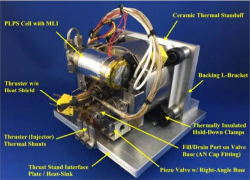
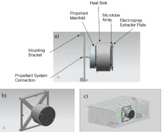
The thruster is composed of a mounting bracket to attach the thruster to the satellite frame, a propellant feed system connection (which is composed of a 1/8-in.-diameter stainless steel tube), a propellant manifold to distribute the propellant, a heat sink to divert heat (large amounts of which are produced when the satellite is operating in chemical mode) away from the more sensitive system components, a microtube array to control the flow of the propellant, and an extractor plate energized to the voltage needed to extract ions during the electric mode.
Figure 3.1. Multi-mode thruster: a) side view, b) front view, and c) placement on 6U satellite bus.
a)
The novel design of the thruster demands an equally unique set of system requirements. The thruster requires 3400 V, similar in magnitude to the voltage created by some power line transformers, to be supplied to the extractor plate in the electric electrospray mode. The rest of the system must be shielded. The ionic nature of the propellant limits the material selection for any system components with which contact is made. Initial work suggested that the system would need to operate at 200 psi, twice that allowed by International Space Station (ISS) regulations. Thus, the thruster is only appropriate for applications where the orbit is well-above or well-below ISS orbit.
3.2. SATELLITE BUS
The satellite bus was developed to address the unique requirements of the thruster system, including demonstrating that the thruster was capable of integration in a 3U and 6U class satellite structure. Challenges, in addition to mass and volume constraints, of integrating the thruster into a CubeSat include: generating sufficient power and voltage, determining/controlling attitude of the spacecraft on-orbit, thermal management, and validating the performance of the thruster. One key challenge is providing the power required by the thruster system and the voltage required for the electric mode without compromising power to other subsystems of the spacecraft. During the electric burn mode, the satellite requires 3400 V in a compact circuit. A second challenge of providing this voltage is reducing the size of a power processing unit such that it fits within a 3U or 6U form factor with the other satellite components while mitigating electromagnetic interference. Other “power hungry” components potentially include reaction wheels, magnetorquers, flight boards, and communications radios. To meet power requirements, deployable solar panels were considered, which would add additional constraints to the attitude, possible slew rates, and pointing of the satellite, along with those required by the communications system. Any thermal effects created during the chemical burn mode must be conducted through the structure and radiated into space. Another challenge is obtaining the hardware for a propulsion system of this size. As most propulsion systems are designed for larger spacecraft, commercial components are often not available for purchase. Finally, validating thruster performance is limited by the accuracy of the guidance, navigation, and control hardware, such as the global positioning system (GPS) and inertial measurement unit (IMU), and the capabilities of the thruster itself. With these considerations in mind, the satellite bus designs described below were produced.
3.2.1. M3
As a 3U CubeSat, space and volume are of particular concern. The scope of the M3 mission was tailored and limited to operating in electric mode only. The primary success criterion is defined as showing that the thruster operated but excludes characterizing how well the thruster operated. This reduced the amount of propellant needed; the complexity of switching between burns; communication requirements; guidance, navigation, and control (GNC) required; and shielding required. Accordingly, the M3 mission objectives follow as:
1) Demonstrate multi-mode thruster operation in electric mode using a single propellant. 2) Demonstrate on-orbit functionality of a multi-mode thruster in electric mode.
3.2.2. APEX
APEX is a 6U CubeSat that houses a full thruster, operable in both chemical and electric modes. Additionally, the thruster performance will be quantified during the APEX mission through both feed system data and measured orbit changes. Additional information regarding orbital maneuvers can be found in Morton and Withrow,26 and thruster validation through feed system data is further discussed in Section 3.3. This validation requires significantly more GNC capabilities and requires large quantities of propellant, compared to the M3 mission. Additionally, more mission flexibility and operator involvement require more complex Command and Data Handling (C&DH) and Communication (COM) systems. Additionally, operating in electric mode for longer time spans requires that the current be alternated between positive and negative charges to avoid charge buildup in the plasma plume that could result in a damaging arc discharge back to the spacecraft. The APEX mission objectives then follow as: 1) Demonstrate integration of multi-mode thruster technology into a small satellite architecture. 2) Determine the on-orbit performance of the multi-mode thruster during chemical and electric
mode burns.
3.2.3. Feed System Components
The propulsion system will be integrated into both a 3U and a 6U structure, demonstrating that such propulsion systems can be practically implemented into most smallsats. Two main challenges must be addressed for successful integration of the propulsion system into the satellite: packaging the system to fit within the volumetric constraints of the structure and sourcing/qualifying a vessel to store the propellant (see Table 3.1). The propulsion system hardware must be as compact as possible as the CubeSat structural envelope only contains 3,000 cm3 of total volume for the 3U (M3) and 6,000 cm3 for the 6U (APEX, see Fig. 3.2). Current methods for conserving volume include optimizing tubing size and feed system configuration. Additionally, the feed system must be constantly adjusted to updated requirements as thruster development progresses.
Table 3.1. Feed System Constraints
Constraint Design Choice
Structures
Volume (3U or 6U) Minimize volume, leaving room for additional payload and bus components Length of structure Propellant storage tube could not exceed
length of longest straight section of structure
Mass Least dense materials used when possible
Payload
Propellant 1) Noncorrosive material for all
components in contact with propellant 2) Leak-proof storage/delivery
Pressure 1) Deliver 200 psi to thruster
2) System originally designed to
withstand 1000 psi on pressurant side and 200 psi operating pressures on propellant side
Integration to thruster Exit tubing size (1/8” diameter) Design in-progress Changing requirements require design
decisions to be made with a large margin of safety and flexibility
Power
Charged during electric mode Insulated propulsion system
Thermal
Propellant must be heated to 373 K Appropriate heat sink path for chemical burn, heating pad on propellant storage tube
System (Internal and External)
Cost Customization/hardware limitations
No student-qualified components Commercial off-the-shelf (COTS) components
No welding (UNP) SAE connections, compression fittings 3 (NASA) or 4 (DoD) inhibits between
propellant and outside of satellite Solenoid valves
Timeline Functioning by the Flight Selection
Review (FSR) for APEX, 18-month project timeline for USIP
Collaboration with Froberg Aerospace Proprietary thruster specifications
Turnover Graduate students involved for
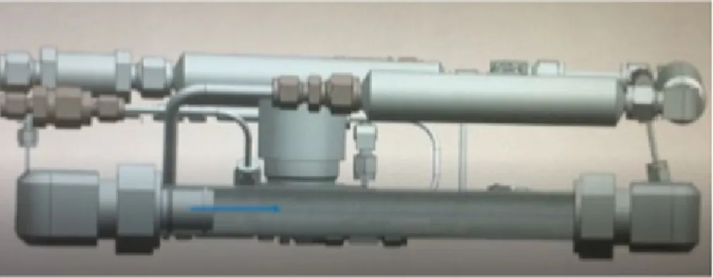
3.2.3.1. Propellant storage. A challenge was encountered in sourcing a space-qualified propellant tank that meets the two CubeSat form size constraints. For example, the original thruster design in the APEX satellite required 150 cubic centimeters (cc) of pressurant and 300 cc of propellant to achieve the desired maneuver durations and meet full mission success criteria for the 6U mission. These volumetric requirements have been updated with additional thruster development to 5 cc and 75 cc, respectively. The diameter of the propellant tank must be less than 10 cm to account for the depth of the structure. Additionally, the length of the tank is constrained by its location in the structure. The mass in the propellant tank will change throughout the mission as propellant is consumed, causing the center of mass of the satellite to change. As such, it is advisable to place the propellant tank lengthwise along the thrust axis to ensure that an excessive moment is not created by the changing center of mass, thereby perturbing the attitude of the satellite. This placement restricts the length of the propellant tank to no more than 20 cm. In order to be compatible with the custom ionic propellant, the tank must be made of a nonreactive material such as stainless steel. The tank was designed to be rated to the pressurant value (in case of a regulator failure) and have a factor of safety of 4.0. A conservative design approach was used under the assumption that the CubeSat would be a secondary payload. A COTS tank was unable to be found, therefore the team designed the needed hardware (Fig. 3.3). However, it became clear after the APEX Preliminary Design Review that the team would encounter excessive scrutiny from launch safety with a student-built pressure vessel. As an alternative approach, the M-SAT team designed a propellant feed system that stores the propellant in the feed system lines, specifically a qualified 1-in.-outer-diameter (OD) stainless steel tube. The pressurization process is similar to an automotive master cylinder brake system. The pressurant provides a force (analogous to the force provided by pressing on the brake) that actuates the piston head. The piston head creates hydraulic pressure on the fluid (propellant, akin to the brake fluid) that is expelled out of the storage area and provided to the thruster when the inhibits are released. This process is shown in Figures 3.4 and 3.5.
The stainless steel tube that stores the propellant in place of a traditional tank is ~10.75 in. long x 1 in. OD, carrying 75 cc of useable propellant for APEX. M3 was designed to pressurize the system in the same manner as APEX. However, the amount of propellant needed is significantly
Figure 3.4. Piston head starting location.
Figure 3.5. Piston head ending location.
lower (5 cc minimum), as well as the operating pressure (~30 to 50 psi). The required operating pressure is significantly lower because M3 will operate in electric mode only. M3 leadership elected to carry extra propellant (~6.6 cc) in order to meet full, rather than minimum, success criteria. Thus, the modified propellant storage tube is ~3.4 in. long x 0.5 in. OD.
If tanks composed of the necessary material are manufactured by a COTS provider in the future, students are advised to perform a trade study to evaluate if the number of connections and leak rate could be reduced with the COTS component.
3.2.3.2. Pressurant tank assembly. The original thruster design for the APEX mission required a pressurant tank assembly with an internal volume of at least 150 cc. The tank needed to be rated to 375 psi with appropriate factor of safety.33 Stainless steel and titanium were determined to be acceptable materials to prevent potential chemical reactions and meet the factor of safety requirements.
A single pressurant tank could not be sourced meeting APEX’s requirements. Therefore, it was decided to connect three Swagelok 50-cc sample cylinders (Swagelok SS4CDTW50) end-to-end as one system. They have a combined pressurant volume of 150 cc and a pressure rating of 1000 psia (Fig. 3.6). The chosen pressurizing agent is nitrogen gas as it does not react with the ionic fluid propellant used for the payload and is more efficient than other considered inert gases (helium and argon).
Figure 3.6. A single Swagelok 50-cc sample cylinder.27
Upon further thruster development, the operating pressure and amount of propellant needed were significantly reduced from the original provided specifications. M3 will use a single, 50-cc sample cylinder and is expected to operate ~50 psi. The final pressurization value will be determined after internal losses are experimentally confirmed. The final operating pressure for APEX is to be determined, based on thruster requirements. At the time of this writing, the team is optimistic that the APEX operating pressure may be reduced to 100 psi and 75 cc. For this operating pressure and volume of propellant, the pressurant tank could be resized to an internal volume of 50 cc, with an expected pressurant tank value of 151.3 psi (see Appendix B.) This value may be adjusted to account for a higher/lower operating pressure or to account for internal losses.
3.2.3.3. Solenoid valves. Solenoid valves should be less than 10 cm in length, rated to a minimum of 200 psia (or current operating pressure), made of stainless steel or titanium, and have Army/Navy (AN), Society of Automotive Engineers (SAE), or Swagelok fittings.
For the APEX satellite, four solenoid valves are used to control propellant flow to the payload (thruster). A total of four valves are utilized for redundancy, ensuring that propellant does not reach the payload prior to deployment from the Planetary Systems Corporation Canisterized Satellite Dispenser (PSC CSD). A fifth valve is placed between the propellant storage system and pressurant side and prevents the propellant from being pressurized until commanded to do so by the flight computer. Additionally, the solenoid valve and check valve ensure that if a propellant leak were to occur during launch, the propellant would not be able to reach the components of the system under higher pressurization (on the pressurant side of the system). The top selection is a derivative of Lee Company’s IEPA series (IEPA1221241H, Fig. 3.7) because of its size, pressure rating, and hold voltage of 1.6 V that can be supplied within the power budget. The valve is 1.3 in. long with a 1-in. port on each side and 0.25 in. diameter. The pressure rating is 800 psia with a proof of pressure of 1600 psia and burst pressure of 2400 psia. The solenoid valve layout for M3 is identical to APEX with one exception: three solenoid valves will be used to control propellant flow to the payload, instead of four. The variance in the design is a result of different inhibit requirements for DoD-sponsored (APEX) versus NASA-sponsored (M3) missions.
Figure 3.7. Lee Company’s IEP series solenoid valve.28
3.2.3.4. Check valves. Check valves must be rated to at least 200 psia (or current operating pressure), made of stainless steel or titanium, and have AN, SAE, or Swagelok fittings. Length should be minimized if possible.
Check valves control the fluid flow through the system, guaranteeing flow in only one direction. Two check valves (one in-line and one at a T-junction) will be used to fill the pressurant tanks and the propellant storage tube prior to launch. Both check valves will then be locked. The third check valve is in-line and will help mitigate the risk of a propellant leak, as it would prevent propellant from being able to reach components under higher pressures (on the pressurant side of the system). A fourth check valve will be placed just before the thruster as another redundancy to prevent heated propellant from flowing backwards into the propellant storage tube should a malfunction occur. Swagelok’s SS-CHS2-1 (Fig. 3.8) and SS-CHS4-1 were chosen because these models have the ability to withstand 6000 psia of pressure, are made of stainless steel, have 1/8- and 1/4-in. connections (standard for the system tubing), respectively, and are relatively compact with a length of 2.14 in.
3.2.3.5. Pressure relief valve. For APEX only, a pressure relief valve will be placed in the pressurant side of the system between the pressure regulator and check valve. This will mitigate pressure buildup over 200 psi in the tubing and ensure that if pressure buildup occurs, nitrogen will be released and contained within the launch canister instead of propellant being released. The pressure valve chosen is the Generant Vent Relief Valve High Pressure (VRVH). This valve can be factory set and locked between the range of 150 and 600 psi and has an option of either a 1/8- or 1/4-in. National Pipe Thread (NPT) connection. This is the only NPT connection in the system and was selected because of its standard connection size. This part was not included in the M3 layout because of volume constraint and lower operating pressures.30
3.2.3.6. Pressure regulation. For APEX, a pressure regulator will be used to adjust the pressurant to the desired operating pressure that may differ for each mode. A pressure regulator is not required by the M3 system because M3 only operates in electric mode at lower operating pressures.
The inlet of the pressure regulator needs to be rated to the current pressure of the pressurant tank assembly as it will experience higher pressure values from the pressurant tank than the outlet will experience. The regulator needs to be able to regulate down to 200 psi (or the current system operating pressure). The regulator should be made out of stainless steel or titanium and use either AN, SAE, or Swagelok fittings.
The pressure regulator will adjust the pressure from the pressurant tanks to 200 psi (or the current system operating pressure). The Emerson Electronics’ mechanical regulator (BB-66PL3KEB4) was chosen to achieve this pressure drop (Fig. 3.9) for the NS-9 competition. The BB-6 series of pressure regulator outputs the propellant at 220 psi and is made of stainless steel. This model was used in the first engineering design unit of APEX. Electric pressure regulators were considered but determined to add risk because of the timeline and lack of team experience. However, with more experience or a longer timeline, it is strongly suggested the team consider an electric version of regulation through either a COTS component or by implementing a “bang-bang” setup for the Nanosat-10 competition. See Section 5.2.1 for more detail.
Figure 3.10. Maxim integrated model DS18S20 pin layout.31
3.2.3.7. Thermal sensors. Thermal sensors must be able to attach to the desired component in a way that will withstand temperature changes and vibration. The thermal sensor selected by the thermal subsystem is the Maxim Integrated model DS18S20 (Fig. 3.10). This model was chosen for ease of integration to the flight computer (through the Flight Computer Interface Board), small size, appropriate temperature operating range, and previous team experience. A thermal sensor will be placed on the propellant storage system to monitor the temperature of the propellant. Additionally, a thermal sensor will be placed on each solenoid valve between the propellant storage system and thruster. If the solenoid valves become heated beyond the desirable temperature range, the flight computer will send a command for the solenoid valves to close so that heated propellant cannot reach the propellant storage tube during a system malfunction.
3.2.3.8. Pressure transducers. Per structure restrictions, the pressure transducer should be less than 10 cm long. It should be rated to at least 200 psia (or the current operating pressure), made of stainless steel or titanium, and have AN, SAE, or Swagelok fittings.
Pressure transducers will be used to measure the pressure in the feed system. One will be placed at the inlet to the propellant storage system to measure the pressure of the stored propellant. The second transducer will be placed at the inlet of the thruster to provide pressure readings as flow enters the payload. TE Connectivity’s miniature EPRB-1 pressure transducer (Fig. 3.11) was chosen because of its size (0.11-mm-diameter diaphragm), ability to withstand high pressure (68.95 MPa), and its required supply voltage (5 V) that is consistent with the voltage supplied by APEX’s power system.
Figure 3.11. TE Connectivity’s miniature EPRB-1 pressure transducer dimensions.32
The reader is referred to the TE Connectivity catalog for thread “A” and length “B” options. In the APEX design, thread “A” is a 10-32 UNF-2A and length “B” is 0.34 inches.32
3.2.3.9. Tubing. To avoid microfluidic effects, such as flow instability and viscosity changes, the tubing should be at least 1/8 in. and rated up to 1000 psia, but size and mass should be minimized. Exceptions may be made to integrate with components with 1/16-in. connections. McMaster-Carr 316 stainless steel tubing will be used. A maximum pressure range is available for this tubing between 1100 and 1600 psi. Lines will be 1/8 in. diameter throughout for consistency except where Swagelok unions will be used to transition to the size of component connections.
3.2.4. Feed System Layout
Figure 3.12 displays the layout of the entire APEX propellant feed system. The pressurant tank contains nitrogen gas, at 375 psi initially, that is regulated to 200 psi by the mechanical pressure regulator. (These values are subject to change because of updates in thruster development.) Check valves are placed at junctions for loading pressurant and propellant near the respective storage areas. Two pressure transducers are also placed at T-junctions just upstream of the propellant storage area and just upstream of the thruster to provide feed system diagnostic data. The in-line check valves and solenoid valves act as inhibits for both the pressurant and propellant, inhibiting reverse flow and ensuring the propellant is not pressurized or provided to the thruster until the appropriate commands are received from the flight computer. The quantity and placement of the inhibits are the result of a full system hazard and operability (HAZOP) analysis performed by M-SAT team members.
Prior to APEX’s integration into the launch vehicle, the three pressurant tanks and the propellant storage system will be filled with 150 cc of nitrogen gas at a total pressure of approximately 375 psi and 75 cc of propellant, respectively, through check valves. One check valve is located just downstream of the pressure tanks and another is located just downstream of the propellant tank.
Figure 3.12. APEX feed system layout.
At this time, the solenoid valves will be closed to prevent any gas or fluid flow. After the tanks are filled, the feed system will be pressurized to 200 psi downstream of the pressure regulator and upstream of the first solenoid valve. Pressure in the feed system will be measured with the pressure transducer just before the propellant tank. When APEX performs a burn, power will be supplied by C&DH to open the four solenoid valves acting as inhibits and allow propellant to flow to the payload. A fifth solenoid valve will be opened allowing the pressurant to move towards the propellant storage system. The propellant feed system will cease providing propellant to the payload when power from C&DH to the solenoid valves is cut off.
The M3 feed system (Fig. 3.13) is laid out in the same configuration, with a few alterations. The M3 mission requires less propellant and, consequently, less pressurant. Thus, only one Swagelok sample cylinder is needed to contain the pressurant. The propellant storage tube holds 6.6 cc of propellant and is significantly shorter than its APEX counterpart. NASA versus DoD sponsorship requires three (instead of four) inhibits, and because of the lower operating pressure, the pressure regulator and pressure relief valve were omitted to meet volume constraints.