CNR-DT 202/2005
ROME – CNR June 2007
NATIONAL RESEARCH COUNCIL
ADVISORY COMMITTEE
ON TECHNICAL RECOMMENDATIONS FOR CONSTRUCTION
Guidelines for the Design and Construction
of Externally Bonded FRP Systems
for Strengthening Existing Structures
Metallic structures
No part of this publication may be stored in a retrieval system, or
transmitted in any form or by any means
– electronic, mechanical, recording, or otherwise –
without the prior written permission
of the Italian National Research Council
.
The reproduction of this document is permitted
for personal, noncommercial use.
CONTENTS
1 FOREWORD ... 1 1.1 PUBLIC HEARING ... 2 2 INTRODUCTION ... 3 2.1 GENERAL CONSIDERATIONS ... 3 2.2 TOPICS... 4 2.3 SYMBOLS... 53 BASIS OF STRENGTHENING AND SPECIAL ISSUES... 7
3.1 BASIC REQUIREMENTS... 7
3.2 PARTIAL COEFFICIENTS... 8
3.2.1 General considerations ...8
3.2.1.1 Partial factors of the metallic substrate (Js) ... 8
3.2.1.2 Partial factors of the FRP strengthening (Jf) ... 8
3.2.1.3 The adhesive/interface partial factor (Ja)... 9
3.2.1.4 Partial factors for resistance models (JRd) ... 9
3.3 SPECIAL DESIGN PROBLEMS AND RELEVANT CONVERSION FACTORS ... 9
3.3.1 Environmental reduction factor (Ka)...9
3.3.2 Reduction factors for long-term effects (Șl) ...10
3.3.3 Impact and explosive loading ...11
3.3.4 Vandalism...11
3.3.5 Strengthening limitations in case of fire...11
4 STRENGTHENING OF TENSILE ELEMENTS ... 13
4.1 INTRODUCTION ... 13
4.2 RESTORING OF THE LOAD BEARING CAPACITY OF DAMAGED ELEMENTS... 13
4.3 UPGRADING OF THE LOAD BEARING CAPACITY OF UNDAMAGED ELEMENTS... 14
4.4 SERVICEABILITY LIMIT STATE ... 15
5 FLEXURAL STRENGTHENING... 16
5.1 FAILURE MODES... 16
5.2 BASIS OF DESIGN ... 18
5.3 SERVICEABILITY LIMIT STATES ... 18
5.3.1 Design checks at time of reinforcement application ...18
5.3.2 Metallic beam design check ...18
5.3.3 FRP design check ...18
5.3.3.1 Local stresses ... 19
5.4 ULTIMATE LIMIT STATES ... 19
5.4.1 Design checks at time of reinforcement application ...19
5.4.2 Flexural capacity ...20
5.4.2.1 Basis of design ... 20
5.4.2.2 Ductile metallic beam... 21
5.4.2.3 Brittle metallic beam ... 22
6 EVALUATION OF THE DEBONDING STRENGTH ... 23
6.1 INTRODUCTION ... 23
6.2.1 Evaluation of shear stresses in the adhesive layer...25
6.2.2 Peeling stress evaluation in the adhesive layer...28
6.2.3 Design check of the delamination strength ...29
7 STRENGTHENING OF FATIGUE SENSITIVE ELEMENTS ... 30
7.1 FATIGUE FAILURE MODES ... 30
7.2 FATIGUE DELAMINATION OF THE STRENGTHENING ... 30
7.3 FATIGUE DAMAGE OF THE METALLIC SUBSTRATE... 30
7.3.1 Introduction ...30
7.3.2 Basis of design...32
7.3.3 Design of the fatigue reinforcement ...34
8 INSTALLATION, MONITORING AND MAINTENANCE ... 35
8.1 GENERAL CONSIDERATIONS ... 35
8.2 RECOMMENDATIONS FOR THE INSTALLATION ... 35
8.2.1 General considerations ...35
8.2.2 Preparation of the substrate surface...35
8.2.3 Structural detailing ...36
8.3 QUALITY CONTROL DURING INSTALLATION ... 37
8.3.1 General considerations ...37
8.3.2 Semi-destructive tests ...38
8.3.3 Non-destructive tests ...38
8.3.4 Personnel qualification ...39
8.4 INSPECTION AND MAINTENANCE ... 39
9 APPENDIX A ... 40
9.1 REVIEW OF STRENGTHENING INTERVENTIONS CARRIED OUT ON EXISTING STRUCTURES ... 40
9.1.1 Hythe Bridge ...40
9.1.2 Tickford Bridge ...40
9.1.3 Slattocks Canal Bridge ...41
9.1.4 Acton Bridge ...41
9.1.5 King Street Bridge ...41
9.1.6 Corona Bridge ...41
9.1.7 Compressed structure of a London Underground tunnel ...42
9.1.8 Christina Creek Bridge ...42
9.2 CURRENT STATE OF ART: EXPERIMENTAL TEST RESULTS... 44
9.2.1 Failure due to delamination ... 44
9.2.2 Flexural strengthening ...45
9.2.3 Fatigue strengthening ...45
9.2.4 Strengthening of compressed elements ...45
10 APPENDIX B: REFERENCES ... 46
1 FOREWORD
The present document adds to the series of documents recently issued by the CNR on the structural use of fiber-reinforced polymer (FRP) composites, started with the publication of CNR-DT 200/2004.
This is an informative document, whose intended objectives are disseminating, within the Technical-Professional community, the knowledge acquired on the use of FRPs in the static consolidation of metallic structures as well as identifying the strengthening interventions that are effectively appropriate and safe.
It is also well-known that the current state-of-the-art on this topic is not as advanced as that of concrete or masonry constructions. In fact, adequate solutions are currently available only for a few specific applications.
No more than the UK and USA guidelines (CIRIA 2004, ICE 2001, Schnerch et al. 2006) on the use of FRP for strengthening metallic structures have been drawn up until now.
The present study represents the first step towards the definition of specific design guidelines that will be issued once all the theoretical studies and experiments have given a more complete and universally accepted understanding of the subject.
The results of this study will be useful in identifying any problems that still remain unresolved, therefore allowing the scientific community to concentrate upon them over the next few years. The current version of this document makes use of some of the basic principles and rules adopted in the document CNR-DT 200/2004, that is relevant to reinforced concrete and masonry structure, while integrating and completing with specific aspects of FRP strengthening interventions with metal structures. In particular, the use of FRP in the flexural and tensile strengthening of structural metal elements is discussed. In addition, several qualitative aspects of debonding as well as the strengthening of fatigue sensitive elements are also dealt with.
The document includes two Appendices, dealing with several examples of FRP strengthening interventions on real structures (Appendix A) and main bibliographic references (Appendix B). The Document derives from the studies developed within the context of important Italian research projects financed by CNR and MIUR.
It is important to highlight that a guideline, by its nature, is not a binding regulation, but merely represents an aid for practitioners interested in the field of composites. Nevertheless, the responsibility of the operated choices remains with the designer.
Finally, the readers not familiar with the technological and mechanical properties of fiber-reinforced composite materials may consult the first Section and the Appendix A of the CNR-DT 200/2004.
This Technical Document has been prepared by a Task Group whose members are:
ASCIONE Prof. Luigi - University of Salerno
CERSOSIMO Dr. Giuseppe - Interbau S.r.l. - Milano
COLOMBI Prof. Pierluigi - Polytechnic of Milano
CREDALI Dr. Lino - Ardea S.r.l. - Casalecchio (BO)
DELLA CORTE Dr. Gaetano - University “Federico II” - Napoli
DI TOMMASO Prof. Angelo - University IUAV - Venezia
FEO Prof. Luciano - University of Salerno
GIACOMIN Dr. Giorgio - Maxfor - Quarto d’Altino (VE)
GIORDANO Dr. Antonella - University of Salerno
GRANDI Dr. Alberto - Sika Italia S.p.a. - Milano
MACERI Prof. Franco - University “Tor Vergata” - Roma
MANFREDI Prof. Gaetano - University “Federico II” - Napoli
MONTI Prof. Giorgio - University “La Sapienza” - Roma
MORANDINI Dr. Giulio - Mapei S.p.a. - Milano
NANNI Prof. Antonio - University “Federico II” - Napoli
OLIVITO Prof. Renato Sante - University of Calabria - Cosenza
PASCALE Prof. Giovanni - University of Bologna
POGGI Prof. Carlo - Polytechnic of Milano
PROTA Dr. Andrea - University “Federico II” - Napoli
ZERBO Dr. Valeria - University IUAV - Venezia
Coordinators:
COLOMBI Prof. Pierluigi, DI TOMMASO Prof. Angelo.
General Coordinator: ASCIONE Prof. Luigi.
Technical Secretariat:
FEO Prof. Luciano, ROSATI Prof. Luciano.
1.1 PUBLIC HEARING
After its publication, this document CNR-DT 202/2005 was subject to a public hearing. Following the public hearing, some modifications and/or integrations have been made to the document including corrections of typos, additions of subjects that had not been dealt with in the original version, and elimination of others deemed not to be relevant.
This Technical Document has been approved as a final version on 18/06/2007, including the modifications derived from the public hearing, by the “Advisory Committee on Technical Recommendation for Construction”, whose members are:
ANGOTTI Prof. Franco - University of Firenze
ASCIONE Prof. Luigi - University of Salerno
BARATTA Prof. Alessandro - University “Federico II”- Napoli
COSENZA Prof. Edoardo - University “Federico II”- Napoli
GIANGRECO Prof. Elio - University “Federico II”- Napoli
JAPPELLI Prof. Ruggiero - University “Tor Vergata” - Roma
MACERI Prof. Franco, Chairman - University “Tor Vergata” - Roma
MAZZOLANI Prof. Federico Massimo - University “Federico II”- Napoli
PINTO Prof. Paolo Emilio - University “La Sapienza” - Roma
POZZATI Prof. Piero - University of Bologna
SOLARI Prof. Giovanni - University of Genova
URBANO Prof. Carlo - Polytechnic of Milano
VINCI Dr. Roberto - Italian National Research Council
2 INTRODUCTION
2.1 GENERAL CONSIDERATIONS
The building patrimony of Italy includes various examples of metallic structures, especially used for industrial purposes.
As in the case of other structural types, the need exists to rehabilitate metal structures due to either design defects or degradation of the load bearing elements, as well as variation in their use.
In several situations, strengthening with Fiber Reinforced Polymer composites (FRP) gives better results. This technical document deals specifically with this reinforcement technique.
A significant part of the Italian architectural and historical patrimony is made up of metallic structures. They have had a fundamental role in the development of the industrialization and contributed to structural theories and studies relative to the strength of materials.
The first structures were made of cast iron and/or forged iron (worked or puddled), but subsequently they rapidly developed along with the evolution of mineral iron forging techniques.
The main cultural reason for restoring the older metallic structures, guaranteeing a structural functionality, is based on the need to preserve not only their historical origins but also the scenery value of the places in which they are located. It is therefore for these reasons that the strengthening should be carried out with the aim of maintaining the original design idea.
The most common type of damage for these structures is connected to the characteristics of the materials. Cast iron often fails upon impact due to its brittleness and cracks when subject to temperature changes, that produce tensile stresses.
Tensile elements made of forged iron often present reductions in the cross sectional area due to corrosion.
Bridges built in the second half of the 19th century and at the beginning of the 20th century are among the oldest and most widespread metal structures, in particular railway bridges are currently still being used. Lack of adequate maintenance, corrosion, as well as fatigue, are the main causes of their degradation.
The increase of traffic volume often requires the strengthening of existing bridge structures. The associated costs of strengthening interventions are often smaller than those needed to either dismantle or reconstruct the bridge, not only from the economical point of view but also from the social one.
The strengthening techniques currently used for either restoring or increasing the load bearing capacity of a metallic structure are based on the application of steel plates, either by bolting or welding. This however has several drawbacks. Steel plates add further loads to the structure and are susceptible to corrosion and fatigue. Often, it can be difficult to weld the reinforcement to the substrate (as an example for a cast iron substrate).
Strengthening of existing metallic structures subjected to traffic loading should be designed in the light of drastically reducing the traffic disruption.
The use of FRP overcomes several of the difficulties associated with the use of traditional reinforcing techniques and materials. FRPs have an elevated resistance/weight ratio, much greater than the steel one. They are also much more resistant to corrosion, if not completely unaffected, as well as extremely easy to be handled.
The use of such materials in strengthening metallic structures is not as developed as its concrete or masonry counterparts. Studies have focused on only some of the possibilities, including:
x strengthening of riveted elements against fatigue crack propagation;
x strengthening of tensile elements, or tensile zone of flexural elements, to reduce the stresses in
serviceability conditions due to either the increase in loads or corrosion. Pre-stressing of the FRP lamina prior to bonding reduces the in service tensile stresses without requiring the preliminary application of temporary preloaded struts to support the flexural elements.
The use of FRP is convenient also in strengthening older metallic constructions, since the mechanical properties of the FRP integrate well with the cast iron ones. The high tensile strength of FRP in the fiber direction as well as the use of the pre-stressing technique compensate the low tensile strength of cast iron.
FRPs can be applied to steel structures either by bonding in situ FRP sheets and thermosetting resin or pultruded laminas, eventually prestressed. Careful attention should be given to the effectiveness of the bonding technique.
With reference to the fiber choice, carbon is often the most adequate due to the fact that it presents values of the Young’s modulus of elasticity similar or greater than that of steel. The same cannot be said for neither glass fiber nor aramid fibers.
The use of carbon fibers however requires an insulating element, to be placed between the composite and the substrate, in order to avoid galvanic corrosion. This is not necessary when glass or aramid fibers are used.
The studies and tests, reported in the literature, highlight that the use of FRPs in strengthening metallic structures is versatile and reliable as well as in constant increase.
2.2 TOPICS
The aim of the Document is to represent the state-of-the-art on the design, installation and monitoring of externally bonded FRP systems for strengthening existing metallic structures. This study represents the first step towards the definition of design guidelines.
The Document deals with:
x basis of strengthening and special issues;
x strengthening of tensile elements;
x flexural strengthening;
x debonding strength;
x strengthening of fatigue sensitive elements;
x installation, monitoring and maintenance.
There are also two Appendices, including several national and international applications of FRP strengthening of steel structures (Appendix A) and the main references on the topic (Appendix B). The remaining topics are approached according to the usual style of technical documents published
by the CNR. The approach of the Eurocodes is adopted; statements are divided between Principles
and Application Rules. Each statement is marked by a progressive numbering, with the principles
being marked by the label (P). Principle statements include the following:
- general statements and definitions of mechanical-structural nature.
- recognized needs and/or analytical models accepted by the scientific community, whose value is universally deemed to be pre-eminent with respect to possible alternatives, unless otherwise explicitly stated.
Application Rules are procedures of widely recognized value, following the Principles and satisfying their needs.
2.3 SYMBOLS General notations
(.)a value of quantity (.) for the adhesive
(.)d design value of quantity (.)
(.)f value of quantity (.) for the fiber-reinforced composite
(.)k characteristic value of quantity (.)
(.)R value of quantity (.) as resistance
(.)s value of quantity (.) for the metallic substrate
(.)S value of quantity (.) as demand
Uppercase Roman letters
As cross section area of the metallic substrate
Af cross section area of FRP reinforcement
Es Young’s modulus of elasticity of the metallic substrate
Ef Young’s modulus of elasticity of FRP reinforcement
Ga shear modulus of adhesive
I moment of inertia of transformed section
Is moment of inertia of the metallic substrate about its centroidal axis, parallel to the reinforced
beam neutral axis
If moment of inertia of the FRP reinforcement about its centroidal axis, parallel to the
reinforced beam neutral axis
MRd flexural capacity of FRP-strengthened member
MSd factored moment
NSd factored axial force
Se static moment about neutral axis of the section part subtended by this axis
T temperature
Lowercase Roman letters
fak adhesive characteristic strength
ffd design strength of FRP reinforcement
ffk characteristic strength of FRP reinforcement
fyk characteristic yield strength of metallic substrate
fyd design yield strength of metallic substrate
fuk characteristic tensile strength of metallic substrate
fsk,sup upper characteristic value of the yielding stress for ductile material, or failure stress for
brittle material
bf width of FRP reinforcement
d distance from extreme compression fiber to centroid of tension reinforcement
tf thickness of FRP reinforcement
ts thickness of the metallic substrate
xe distance from extreme compression fiber to neutral axis
Uppercase Greek letters
.eff stress intensity factor
.eff,th threshold value of .eff for crack propagation
Y non-dimensional stress intensity factor range
Lowercase Greek letters
Įf coefficient of thermal expansion of the reinforcement
Ȗ partial factor
ȖRd partial factor for resistance models
İ0 initial strain prior to strengthening
İ(t) tensile strain
İ(c) compression strain
İfa strain at adhesive-reinforcement layer
İsa strain at metallic substrate-reinforcement layer
Ȥ curvature
K conversion factor
Ka environmental conversion factor
Kl conversion factor for long-term effects
ı0 metallic substrate normal stress prior to strengthening
ıf FRP reinforcement normal stress
ıfp FRP reinforcement prestress
ıs metallic substrate normal stress
ısp compressive stress in metallic substrate due to the FRP prestress
fk
3 BASIS OF STRENGTHENING AND SPECIAL ISSUES
3.1 BASIC REQUIREMENTS(1) P The purposes of the FRP strengthening of metallic structures include:
x increasing or restoring the tensile strength;
x increasing or restoring the flexural strength;
x increasing the fatigue resistance.
Recent studies have also highlighted the possibility of increasing or restoring the load bearing capacity of thin compressed elements. Nevertheless, the number of studies currently available, from both the theoretical and experimental point of view, is still few, in order to define reliable design procedures.
(2)P The FRP strengthening described in this document consist of the application of either pultruded laminates or impregnated sheets to the external surface of the structural elements.
(3)P The strengthening design should be aimed at guaranteeing a tensile stress state within the FRP strengthening. In such a case, the FRP strengthening can be fully functional in addition to the tensile stress present within the metal support element. The use of FRP in a compressive zone is currently not recommended due to the lack of adequate models and tests relative to the delamination phenomena in the presence of compressive stresses.
(4)P FRP-strengthened metallic structures, subject to cyclic stresses, including those deriving from thermal cycles can deteriorate over time. In order to reduce this potential failure mode, additional mechanical connectors can be applied to the strengthened area.
(5)P FRP strengthening should be applied to structural elements with adequate characteristics. If the metallic substrate is in an advanced corroded state, the oxides must be completely removed, taking great care to restore the original profile of the support.
(6)P The FRP reinforcement should be selected in order to be compatible with the environmental
conditions (temperature, humidity, UV radiations, etc.) to which it will be exposed, avoiding the formation of galvanic currents.
(7)P In the case of FRP strengthening of fatigue-sensitive elements as well as when using the prestressing technique creep phenomena of the adhesive should be taken into account. In particular cases, when considered to be necessary, it is possible to integrate the FRP-metal joint with permanent mechanical connectors.
(8)P The FRP strengthening of existing metallic structures can be carried out only when the original structure fulfill the ultimate limit state (ULS) requirements with reference to the quasi-permanent load combination (as defined in the current design Codes) and using the values of the partial factors for exceptional loading condition.
(9)P The design should take into account the possible accidental damage or degradation of the FRP reinforcement under usual working conditions, incorporating eventual protection systems.
(10)P In the case of an historical structure or monument being strengthened, a specific justification should be given to the need for an immediate intervention and full compatibility of the
reinforcement with the existing structure, in accordance with the consolidated Restoration principles. The requirements set out in (8)P should not be applied to this type of structures.
3.2 PARTIAL COEFFICIENTS 3.2.1 General considerations
(1)P The values of the materials and products properties used for the strengthening should be determined in accordance to the indications set out in the Document CNR-DT 200/2004.
(2)P The design strength of a FRP strengthened metallic element can be expressed as follows:
^
`
k,id d,i d,i d,i
Rd Rd m,i 1 1 ; X ; R R X a R K a J J J ½ ° ° ® ¾ ° ° ¯ ¿ , (2.1)
whereR
^`
is a suitable function for the specific mechanical model being considered (e.g. flexure,shear, etc) and JRd is a partial factor covering uncertainties of the assumed model. The arguments
of the function R
^`
are typically the design values Xd,i of the i-th materials used for strengthening,or the existing materials, and the nominal values ad,i of the i-th geometrical parameter involved in
the model. In addition, K is a conversion factor that takes into account, in a multiplicative manner,
special design issues, while Jm,i is the partial coefficient of the i-th material and product.
3.2.1.1 Partial factors of the metallic substrate (Js)
(1)P If the substrate is made of a metal provided of specific design Code, the partial factors should then be applied.
(2)P In general, the partial factor of a ductile metal (steel, “old” iron,) is different to that of a brittle metal (cast iron). In the case of brittle metals, with reference to the failure consequences, an higher value of partial factors should be adopted.
(3) It is well known that a brittle metal structure is designed with the “admissible” stresses
method (i.e. in the elastic field of response). Verification through the limit state method, as set out in this document, requires the use of a partial factor of the material. In the case of a ductile substrate, the indications set out in the existing Codes could be used, while for “old” iron as well as cast iron specific tests are required.
3.2.1.2 Partial factors of the FRP strengthening (Jf)
(1)P The partial factors of FRPs depend on both the installation method as well as the quality of the application. Table 3-1 suggests values of partial factors for the ultimate limit state, as they are set out by the CNR-DT 200/2004:
Table 3-1 – ULS partial factors Jf.
Type A Application Type B Application
1.10 1.25
Type A Application Strengthening system with certification of each component as well as the final product to be applied to a given support.
Type B Application Strengthening systems certified for each component only.
(2) For the serviceability limit states, the value of Jf is equal to 1. 3.2.1.3 The adhesive/interface partial factor (Ja)
(1)P The partial factors of the adhesive/interface used to join the FRP to the substrate, depend on
both the installation method and the quality of the application. Particular attention should be given to the evaluation of the thickness of the adhesive layer in the definition of the partial factor. In a type A application the adhesive thickness should be controlled. At the ultimate limit states the values listed in Table 3-2 are suggested.
Table 3-2 – ULS partial factors Ja.
Type A application Type B application
1.20 1.50
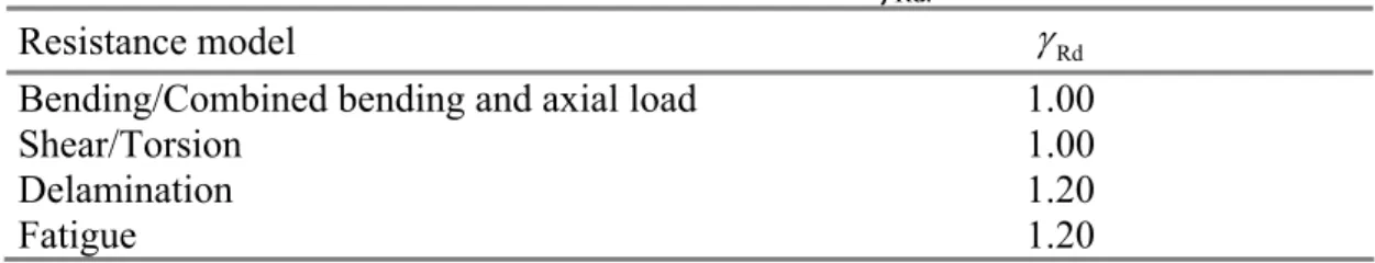
3.2.1.4 Partial factors for resistance models (JRd)
(1) For ULS, values to be assigned to the partial factors JRd are reported in Table 3-3.
Table 3-3 – Partial factors JRd.
Resistance model JRd
Bending/Combined bending and axial load 1.00
Shear/Torsion 1.00 Delamination 1.20 Fatigue 1.20
3.3 SPECIAL DESIGN PROBLEMS AND RELEVANT CONVERSION FACTORS
(1) Hereafter some reference values to be assigned to the conversion factor Ș=Șa·Șl, that affects
both the durability and behavior of the FRP materials, are reported.
3.3.1 Environmental reduction factor (Ka)
(1)P Mechanical properties (e.g. tensile strength, ultimate strain, and Young modulus) of FRP systems degrade under specific environmental conditions such as: alkaline environment, moisture (water and saline solutions), extreme temperatures, thermal cycles, freeze and thaw cycles, and ultraviolet radiations (UV).
(2) Effects of alkaline environment. The damage of the resin due to alkaline environment is
typically more dangerous than the one due to moisture. The resin shall complete its curing process prior to be exposed to alkaline environment.
(3) Effects of moisture. The main effects of moisture absorption concern the resin and they can
be summarized as follows: plasticization, reduction of glass transition temperature, strength and stiffness (the latter less significant). The absorption of moisture depends on the type of resin, the composition and quality of the laminate, the thickness, the curing conditions, the resin-fiber
interface, and the working conditions. In a marine environment, where osmotic effects may cause the presence of air pockets in the resin, it is suggested to use protective coatings.
(4) Effects of extreme temperatures and thermal cycles. The primary effects of temperature
concern both viscous response of resin and composite. As the temperature rises, the Young modulus of elasticity of the resin lowers. If the temperature exceeds the glass transition temperature, the performance of FRP materials significantly decreases. In general, thermal cycles do not have detrimental effects on FRP; however, they may cause the formation of micro-fractures in systems with an high resin Young modulus. For typical temperature levels in civil infrastructures, undesired performance can be avoided by choosing a system where the glass transition temperature is always higher than the maximum operating temperature of the structure or component being strengthened.
(5) Effects of freeze and thaw cycles. In general, exposure to freeze and thaw cycles does not
have an impact on FRP performance, whereas it lowers the resin performance as well as the fiber-resin interface. For temperatures below 0 °C, polymeric based-fiber-resin systems may improve their performance by developing higher strength and stiffness. The effects of the degradation induced by freeze and thaw cycles may be magnified by the presence of moisture.
(6) Effects of ultraviolet radiations (UV). Ultraviolet radiations rarely degrade the mechanical
performance of FRP-based systems, although this may cause some resins to have a certain degree of brittleness and surface erosion. In general, the most harmful effect linked to UV exposure is the penetration of moisture and other aggressive agents through the damaged surface. FRP-based systems may be protected from such damages by adding fillers to the resin or by providing appropriate coatings.
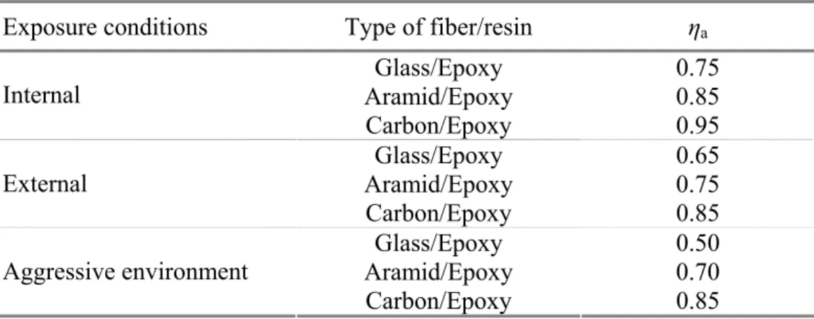
(7) Table 3-4 summarizes the values to be assigned to the environmental reduction factor Ka,
depending upon fiber/resin type and exposure conditions. Such values represent conservative estimates based on the durability of different fiber types. Values as reported in this table may be
increased by 10% (however Ka d1 shall always be satisfied) whenever protective coatings are
used. Such coatings need to be maintained on the strengthened structure for its entire life and need to be experimentally tested and proven to be effective in protecting the FRP system from the environmental exposure.
Table 3-4 – Environmental reduction factor Ka for different exposure conditions and FRP systems.
Exposure conditions Type of fiber/resin Șa
Glass/Epoxy 0.75 Aramid/Epoxy 0.85 Internal Carbon/Epoxy 0.95 Glass/Epoxy 0.65 Aramid/Epoxy 0.75 External Carbon/Epoxy 0.85 Glass/Epoxy 0.50 Aramid/Epoxy 0.70 Aggressive environment Carbon/Epoxy 0.85
3.3.2 Reduction factors for long-term effects (Șl)
(1)P Mechanical properties (e.g. tensile strength, ultimate strain, and Young modulus of elasticity) of FRP-based systems degrade due to creep, relaxation, and fatigue.
(2) Effects of creep and relaxation. For FRP-based systems, creep and relaxation depend on the properties of both resins and fibers. Typically, thermosetting resins (unsaturated polyesters, vinyl esters, epoxy and phenolic resins) are less viscous than thermo-plastic resins (polypropylenes, nylon, polycarbonates, etc.). Since the presence of fibers lowers the resin creep, such phenomena are more pronounced when the load is applied transversely to the fibers or when the composite has a low volume ratio of fibers.
Creep may be reduced by ensuring low serviceability stresses. CFRP, AFRP, and GFRP systems are the least, moderately, and most prone to creep rupture, respectively.
(3) Fatigue effects. The performance of FRP systems under fatigue conditions also need to be
taken into account. Such performance depends of the matrix composition and, moderately, on the type of fiber. In unidirectional composites, fibers usually have few defects; therefore, they can effectively delay the formation of cracks. The propagation of cracks is also prevented by the action of adjacent fibers.
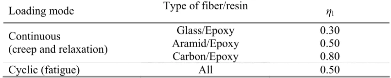
(4) In order to avoid failure of FRP strengthened members under continuous stress or cyclic
loading, values of the reduction factor for long term effects, Kl, are suggested in Table 3-5. In the
case of combined continuous or cyclic loading, the overall reduction factor may be obtained as the product of the pertaining reduction factors.
Table 3-5 – Reduction factor for long-term effects Șl for different FRP systems.
Loading mode Type of fiber/resin Șl
Glass/Epoxy 0.30 Aramid/Epoxy 0.50 Continuous
(creep and relaxation)
Carbon/Epoxy 0.80
Cyclic (fatigue) All 0.50
3.3.3 Impact and explosive loading
(1) The behavior of FRP systems subjected to impact or explosive loading is not completely
understood yet. First indications suggest choosing AFRP (more resistant to impact) and/or GFRP systems rather than CFRP.
3.3.4 Vandalism
(1)P FRP composite materials are particularly sensitive to cuts and incisions produced by cutting
tools.
(2) Particular protection systems need to be used for FRP strengthened members open to the
public where vandalism could be an issue. The safety of the structural member shall be checked, assuming that the FRP system is no longer in place. Design shall be verified using the combination for quasi-permanent loads while the material partial factors at ULS shall be considered for exceptional loading.
3.3.5 Strengthening limitations in case of fire
(1)P FRP materials are particularly sensitive to high temperatures that may take place during fire.
When the room temperature exceeds the glass transition temperature of the resin (or the melting temperature in the case of semi-crystalline materials) both strength and stiffness of the installed FRP system are reduced. In the case of FRP applied as an external reinforcement to steel members,
exposure to high temperature produces a fast degradation of the bond between the FRP system and the support. As a result, degradation of the strengthening effectiveness and debonding of FRP composite may take place.
(2) During fire exposure, mechanical properties of FRP strengthened members may be
improved by increasing the thickness of protective coatings. It is suggested to use coating capable of reducing the spreading of flames as well as smoke production. It is also recommended to use protective coating systems provided with official certificates. Further specifications on the application of protective coating systems are reported in CNR-DT 200/2004.
(3)P In order to prevent collapse of the FRP strengthened structure, as long as further information
on the actual behaviour of coatings and resins under fire exposure is not available, it is recommended to keep low the FRP contribution to the member capacity.
(4) It is suggested that the combination for exceptional loading (fire), as defined by the current
building code, takes as a reference the situations hereafter listed, where the design value of the
effect of indirect thermal loading is indicated by the symbol Ed.
x Exceptional loading with FRP strengthening still in place (Ed z0), when the strengthening
system has been designed to withstand fire exposure. Applied loads need to be considered at SLS and load factors in compliance with frequent loading conditions. In this case, all loads acting on the structure for the frequent combination are to be considered. The member capacity, reduced to take into account the duration of fire exposure, shall be computed with the partial factors pertaining to exceptional situations, according to the current codes (for
FRP Jf 1).
x Situation following an exceptional event (Ed 0), when the strengthening system is no
longer in place. Applied loads need to be considered for quasi-permanent loading conditions. The member capacity, reduced to take into account the duration of fire exposure, shall be computed with the partial factors pertaining to exceptional situations.
4 STRENGTHENING OF TENSILE ELEMENTS
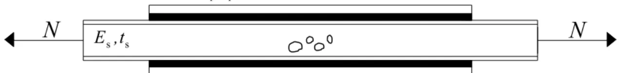
4.1 INTRODUCTION(1)P This chapter deals with the strengthening of steel tensile elements by FRP materials. The strengthening can be applied for the restoring of the load bearing capacity of partially corroded elements (Figure 4-1) as well as for the upgrading of the failure load of undamaged elements (Figure 4-2). f f E ,t s s E ,t
N
N
Figure 4-1 – Tensile element with partially corroded cross section and symmetric reinforcement.
f f
E ,t
s s
E ,t
N
N
Figure 4-2 – Undamaged tensile element with symmetric reinforcement.
(2) In the following, reference is made to double-symmetric strengthening since this
configuration avoids the presence of secondary bending moments.
(3)P The failure mode of tensile elements strengthened by FRP materials can be associated to:
x failure of the metallic substrate;
x failure of the FRP reinforcement;
x failure due to delamination.
The following recommendations refer to the first two failure modes. Delamination must be checked according to the information given in Section 6.
(4)P The evaluation of the structural capacity of a reinforced section is based on the following hypotheses:
x cross section of the reinforced element remains plane;
x perfect bond between the strengthening and the substrate;
x linear elastic behaviour of the materials (isotropic for the metallic substrate and orthotropic
for the FRP reinforcement).
4.2 RESTORING OF THE LOAD BEARING CAPACITY OF DAMAGED ELEMENTS
(1)P On the conservative side, restoring of the load bearing capacity of damaged elements, not subjected to fatigue (Section 7 deals with fatigue), is performed assuming that the stresses across the damaged section are bridged by the FRP materials. The strengthening must be designed such that:
fk f s sk,sup f 2 A f K A f J t , (3.1) where:
- Af is the cross section area of the FRP;
- ffk is the lower characteristic value of the composite tensile strength;
-Jf is the partial factor of the reinforcement material (§3.2.1.2);
-K is the conversion factor (§3.3.1);
- As is the cross section area of the metallic substrate;
- fsk,supis the upper characteristic value of the yielding stress (fy) for ductile material, or failure stress
(fu) for brittle material.
Note that in (3.1) the model partial factor,JRd, is not present since it is assumed to be equal to 1
(Table 3-3, § 3.2.1.4).
(2) If a more accurate determination is not available, the upper characteristic value of the
yielding or failure stress can be evaluated by multiplying the nominal characteristic value by 1.35.
4.3 UPGRADING OF THE LOAD BEARING CAPACITY OF UNDAMAGED ELEMENTS
(1) The normal stress, ıs, in the metallic substrate, taking into account the mismatch between
the thermal expansion coefficient of the strengthening and the substrate, is given by:
Sd f f f s s s f f s s 2 2 N E A T E E A E A D D V ª¬ ' º¼ . (3.2)(2) The normal stress , ıf, in the reinforcement is given by:
Sd s s s f f f f f s s 2 N E A T E E A E A D D V ª¬ ' º¼ , (3.3) where:- NSd is the design load;
- Ef and Af, are the modulus of elasticity and the cross section area of the strengthening,
respectively;
-Įf is the coefficient of thermal expansion of the reinforcement;
-Įs is the coefficient of thermal expansion of the substrate;
-ǻT is the change in temperature after the strengthening application;
- Es and As, are the modulus of elasticity and the cross section area of the metallic substrate,
respectively.
sk s s Rd fk f f Rd , , f f V J J V K J J d d (3.4)
where fsk, ffk,Js , Jf ,JRd, K,are defined in § 4.2.
4.4 SERVICEABILITY LIMIT STATE
(1)P In service condition, the stresses in the composite, evaluated with reference to the quasi-permanent load combination, must be Vf d K ffk, where ffk is the characteristic failure stress and K
is the conversion factor, given by § 3.3.
(2)P In the metallic substrate, the design checks required by the current Building Code must be performed.
5 FLEXURAL STRENGTHENING
5.1 FAILURE MODES(1)P Failure modes occurring in beams are listed below:
- tension failure of either the metallic beam (fracture or yielding depending upon the type of base material) or FRP (Figure 5-1(a) and Figure 5-1(b));
- compression failure of the metallic beam (yielding or local buckling) (Figure 5-1 (c));
- delamination ((i) at the interface between the composite reinforcement and the metallic beam, (ii) inside the composite reinforcement, (iii) inside the metallic beam);
- shear failure by local buckling at the beam supports;
- global buckling (either axial or lateral-torsional) of the metallic beam.
In any case, only the composite reinforcement applied in the tension zone must be taken into account.
a) Tension failure of the support beam q
b) Tension failure of the composite strengthening
q
c) Local buckling of the support beam q
d) Delamination
q
q e) Shear failure
Figure 5-1 – Failure modes of a metallic beam strengthened with FRP and loaded in flexure. In the following, the possible failure modes are briefly described, giving also some information regarding the design checks against tension, compression or delamination failure mode.
1) Tension failure of either the metallic beam or FRP
Some ancient metallic members are made of cast iron, which is a material exhibiting brittle failure when subject to tension. In such a case, the design is usually addressed at reducing normal stresses produced by service dead and live loads, in order to increase safety against failure at the tensile side of the metallic member. This is a fundamental difference with respect to the case of strengthening reinforced concrete beams, where it is usually accepted the tensile flexural cracking.
With reference to cast iron beams, the use of pre-tensioned FRPs may be found particularly useful, if not mandatory, since in this case a reduction of the tensile stresses in the substrate is achieved without a preliminary reduction of the stresses due to live loads.
In the case of metallic beams exhibiting ductile failure (wrought iron, steel) the composite strengthening has the function of reducing stresses in the metallic beam under service loads (in order to increase the fatigue resistance), as well as increasing the ultimate load bearing capacity of the composite strengthened beam, with respect to the un-reinforced situation, allowing the development of post-elastic deformation capacity of the metallic beam thanks to the FRP high tensile strength. In fact, even if tensile failure of FRP is brittle, the development of inelastic deformation in the metallic beam can result in a ductile composite system, until the delamination of the strengthening FRP system takes place.
2) Compression failure of the metallic beam
Compression failure of the metallic beam occurs with different modes according to the type of the substrate material and geometry of the cross section. Some metals, such as cast iron, are characterized by strong non linearity in tension, with gradual stiffness reduction. On the contrary, wrought iron and steel exhibit clear yielding. Once the type of stress-strain response is known, the geometry of the cross section will dictate the type of failure mode. In fact, depending on the local slenderness and the ratio between the Young modulus and the elastic limit stress, local buckling may occur either before or after some inelastic deformation takes place. In the case of steel beams, modern design Codes, such as Eurocode 3 (EN 1993-1-1), give rules for establishing the type of the compression failure mode. In the case of cast or wrought iron, specific investigation is required to ascertain the type of failure mode in compression. However, an approximate estimate of the buckling stress may be obtained by using classical formulae of metallic beams, using inertia properties of an homogeneous beam equivalent to the actual composite one.
3) Delamination
The analysis of the composite section, made up of the metallic beam and FRP, is usually carried out under the assumption of a perfect bond between the metallic beam and the strengthening FRP. But, this is not the actual situation, due to the adhesive always being made of a thin but finite and deformable layer of material. Strong stress and strain concentration normally occurs at the interface between the metallic beam and the FRP, where discontinuities occur, such as at the end of the strengthening FRP or in correspondence of cracks in the metallic beam. This stress concentration is at the origin of failure by delamination, which will be deeply described later on Section 6.
4) Shear failure
Since the flexural strengthening implies an increase of the acting vertical loads, it is necessary to check the beam against both shear and local buckling failure close to the supports.
5) Global buckling of the beam
The composite metal-FRP beam will be characterized by better inertia properties in relation to the original bare metallic beam. This will improve its resistance against global buckling phenomena. Reference is made to recommendation given at Section 3.1.
(2)P The design of the composite metal-FRP beam must adequately consider fatigue effects. Fatigue failure may occur not only in the metallic beam, but also in the FRP strengthening or within the adhesive. Criteria for checking safety against failure by fatigue are given in Chapter 7 of these Guidelines.
5.2 BASIS OF DESIGN
(1)P Analysis of stress and strain state on the cross section of a metallic beam strengthened with
FRP must be carried out taking into account of the initial state immediately prior to the strengthening. Stresses and strains in the metallic beam are obtained by superposition of those produced by loads acting before strengthening and those produced on the whole composite FRP-metal beams by loads acting subsequently to the strengthening application. For serviceability limit state checking, the initial stresses can be summed up to those produced on the composite FRP-metal beam after the application of the strengthening FRP system. For ultimate limit state, the initial strains can be summed up to those produced on the composite FRP-metal beam after the application of the strengthening FRP system.
(2)P In the case of flexural strengthening of existing beams characterized by corrosion and/or
damage of different nature geometrical dimensions used in calculations must be derived by in situ
measurements.
(3) Analysis of the stress-strain state of a FRP strengthened metallic beam and subject to
bending moments is carried out on the basis of the following main assumptions:
- perfect bond (i.e. no slip) between the metallic beam and the FRP strengthening system;
- plane sections remain plane after deformation;
- negligible thickness of the strengthening system with reference to the section depth;
- negligible contribution of the adhesive layer to the stiffness of the member.
The meaning of the first two hypotheses is well known and established. The third assumption allows for the FRP strengthening system to be assimilated to one single fiber, at the same level of the metallic beam fiber to which it is glued. The last hypothesis is justified by the very small value of the Young modulus of the adhesive (resin) material with respect to the metallic beam one (about 1/100), in addition to the small thickness of the adhesive layer.
5.3 SERVICEABILITY LIMIT STATES
5.3.1 Design checks at time of reinforcement application
(1)P Analysis of the beam behavior at SLS must consider the initial stress, V0, acting in the
metallic beam immediately before strengthening.
(2)P Linear elastic response of all the materials is assumed at SLS.
5.3.2 Metallic beam design check
(1)P The metallic beam must be checked against all the serviceability limit states suggested by existing design Codes and/or standards of practice.
5.3.3 FRP design check
(1)P Stresses induced by the quasi-permanent load combination in the strengthening FRP system
(2) In the case of plane stress states, the following limitation should be applied: 2 2 2 fk fk f V W K W § · § · d ¨ ¸ ¨ ¸ © ¹ © ¹ . (3.5)
Symbols used in Equation (3.5) have the following meaning:
-V and W are the normal and shear stresses, respectively, acting at the generic point of the composite
FRP strengthening system;
- ffkis the characteristic value of the tension strength of the composite FRP strengthening system;
- Wfk is the characteristic value of the shear strength of the composite FRP strengthening system,
measured in the direction perpendicular to the beam axis;
-Kis the conversion factor (Section 3.2).
5.3.3.1 Local stresses
(1) Both normal and shear local stresses can be computed using available formulations for the
analysis of composite sections in the linear-elastic range. The composite FRP-metal beam can be reduced to an equivalent homogeneous beam, by means of coefficients given by the ratio between the Young modulus of the i-th material and a reference material constituting the composite cross section.
5.4 ULTIMATE LIMIT STATES
5.4.1 Design checks at time of reinforcement application
(1)P The ultimate limit state is checked by verifying the following Equation:
Sd Rd
M dM , (3.6)
where MSd is the bending moment produced by the design load combination and MRd is the design
value of the flexural capacity.
(2)P The initial strain, H0, at the extreme fiber of the beam cross section, prior to strengthening,
must be considered (Figure 5-2).
H
0H
0After strengthening Prior to strengthening
5.4.2 Flexural capacity 5.4.2.1 Basis of design
(1)P The ultimate limit state is reached when the strain acting at the extreme fiber of the cross section equals a limit value. The latter must be established on the basis of the failure modes previously described. For instance, limit values of strains to be considered for a metallic beam strengthened in the tension zone are the following:
^
`
(t) (t) (t) d min sd; fd 0 H H H H , (3.7) (c) (c) d sd H H , (3.8) (t) sdH and Hfd(t) being the design values of the tension strain capacity of the substrate and strengthening
FRP, respectively, H0 is the initial strain previously defined, Hsd(c) is the design value of the
compression strain capacity of the substrate.
The smallest bending moment corresponding to the fulfillment of the condition (3.7) or (3.8) is the flexural capacity of the strengthened beam.
(2) Design values of strain capacity are calculated starting from the characteristic values,
applying the partial and conversion factors introduced at Section 3.2.
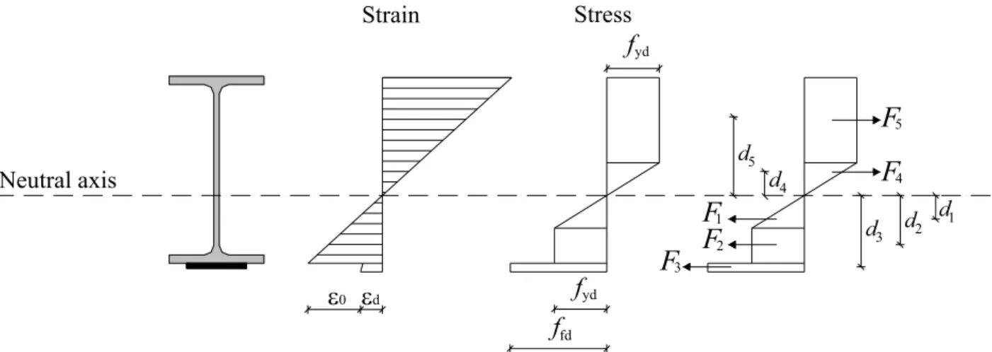
(3) The design flexural capacity, MRd, can be computed using the following procedure:
a) assume that one of the materials composing the cross section has reached, at the extreme fiber of the cross section, its strain capacity, as specified in (1)P;
b) fix a first value of the neutral axis position; this will fix the whole strain state on the cross section because of the assumption of a linear strain distribution (plane sections remain plane);
c) evaluate stresses at each fiber of the cross section, based on the appropriate stress-strain relationship and applying appropriate conversion factors for the FRP strengthening system (Section 3.3);
d) check equilibrium of resultant forces in the direction of the beam axis; for example, with reference to Figure 5-3, the following Equation must be satisfied:
1 2 3 4 5
F F F F F ; (3.9)
e) if Equation (3.9) is not satisfied then go back to step b) and repeat steps b), c) and d) with iteration on the neutral axis position, until Equation (3.9) is satisfied;
f) once determined, the neutral axis position allowing satisfaction of Equation (3.9), the design value of the flexural capacity associated to the considered failure mode can be easily computed. For example, with reference to Figure 5-3, the following Equation applies:
Rd i i
M
¦
F d , (3.10)where the partial factor JRd has been set equal to 1 (Table 3-3, § 3.2.1.4).
(4) The stress-strain relation for the FRP strengthening system is always linear up to failure. The
relevant Young modulus, to be used in the procedure above outlined, is the one measured for the FRP system in the direction parallel to the beam axis. Since the FRP strengthening system is often
placed with fibers aligned parallel to the direction of the beam axis, thus maximizing its efficiency, the Young modulus of the FRP strengthening system often coincides with the modulus measured parallel to the fiber direction.
The stress-strain relation of the metallic beam depends upon the type of material, being different in the case of a ductile metal (wrought iron, steel) or in the case of a brittle metal (cast iron), as will be discussed in Sections 5.4.2.2 and 5.4.2.3.
H0 Hd fyd yd f ffd
F
5 4F
F
1F
2F
3 1 d d2 d3 4 d d5 Neutral axis Stress StrainFigure 5-3 – Procedure for computing the flexural capacity.
5.4.2.2 Ductile metallic beam
(1) If the metallic beam is made of a ductile material (wrought iron, steel), exhibiting clear
yielding when subject to axial loading, then the stress-strain relation to be used in the evaluation of the flexural capacity can be assumed as elastic-perfectly plastic. The design value of the yield stress can be computed according to the information provided at Section 3.2.
(2) In the case of a metallic beam made of a ductile material, it is possible to reduce the number
of possible failure modes. Using definitions suggested by Eurocode 3, if the cross section of the metallic beam is of class 1 or class 2, then failure will occur due to excessive strain reached in the FRP strengthening system. If the cross section is of class 3, then failure will occur due to either yielding in the metallic beam or excessive strain in the FRP strengthening system. If the cross section is of class 4, then failure will occur because of either local buckling of the compression flange of the metallic beam or excessive strain reached in the FRP strengthening system. Hence, limit values of strain in the metallic beam and in the FRP strengthening system can be set as follows:
- class 1 or 2 cross section:
(t) (t) d fd 0 (c) d H H H H ° ® f °¯ ,
- class 3 cross section:
^
`
(t) (t) d yd fd 0 (c) d yd min ; H H H H H H ° ® °¯ ,
- class 4 cross section:
(t) (t) d fd 0 (c) (LB) d d H H H H H ° ® °¯ ,
where Hyd is the design value of the yielding strain of the substrate (assumed to be equal both in
tension and compression), (LB)
d
buckling and other symbols have the meaning already defined in previous Sections. The peak compressive strain corresponding to local buckling can be computed as the ratio of the peak stress inducing local buckling, Vd(LB), and the Young modulus, Es, of the substrate.
5.4.2.3 Brittle metallic beam
(1) In the case of a brittle metal (cast iron), the stress-strain relation is non-linear in tension and
linear in compression. Design limit values of stress and strain must respect the information given at section 3.2.
(2) In the case of a metallic beam made of a brittle material, there is no available classification
of the cross section allowing a priori selection of the type of failure mode. Then, all the limits
associated with potential failure modes will be checked.
(3) In the case of a metallic beam made up of a brittle material, already cracked at the time of
strengthening, the FRP reinforcement system may be used to bridge the tensile stresses over the crack location. Particular caution is required to avoid local delamination of the FRP strengthening, in correspondence of the cracks in the metallic beam. In fact, there is no validated method for checking safety against local delamination.
6 EVALUATION OF THE DEBONDING STRENGTH
6.1 INTRODUCTION(1) This chapter deals with the delamination failure mode of the FRP reinforcement. Debonding
of the reinforcement from the metallic substrate and the relevant drastic reduction of the bearing capacity of the structural element is called “delamination”. Delamination is due to both the peeling and shear stress in the adhesive layer. Moreover, stresses are present in the FRP reinforcement too and they can lead to the composite delamination. From a theoretical point of view, delamination failure could also take place in the metallic substrate. Nevertheless, the usual hierarchy of resistance (for increasing resistance) is the following: adhesive joint, reinforcement and substrate. It is worth noting that this hierarchy of resistance is not the usual one achieved in RC or masonry structures where the weakest element is given by the substrate where delamination failure takes place. In the literature two different models have been proposed to analyze the delamination problem:
x a conventional stress approach, based on the elastic analysis of the stress field;
x a fracture mechanics approach, based on linear elastic fracture mechanics concepts.
The present chapter deals only with the stress-based approach since the fracture mechanics one, although more appropriate from a theoretical point of view, requires additional theoretical studies and experimental validations.
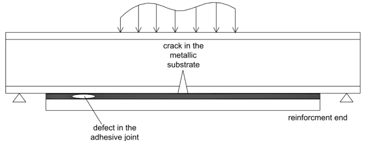
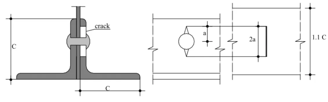
(2)P As shown in Figure 6-1, delamination takes place in high-stresses concentration zones, often
produced by discontinuities in the reinforcement or cracks in the metallic substrate.
defect in the adhesive joint crack in the metallic substrate reinforcment end
Figure 6-1 – Discontinuity examples in the metallic substrate, adhesive and FRP strengthening.
(3)P Delamination of a strengthened element can take place in the reinforcement, in the substrate
or at the interface. In a strengthened element with a metallic substrate, the possible delamination failure modes are listed below, as shown in Figure 6-2:
x delamination at the substrate - adhesive or adhesive - FRP interface;
x cohesive failure of the adhesive;
As stated above, differently from what usually occurs in strengthened RC structures, delamination does not take place in the metallic substrate but in the adhesive (cohesive failure), at the interface (interface failure) or in the reinforcement (FRP delamination). Nevertheless, if the substrate is made of wrought iron, delamination can also take place in the substrate similarly to what occurs in RC or masonry structures. metallic substrate adhesive FRP metal/FRP interface adhesive/FRP interface adhesive layer FRP delamination
Figure 6-2 – Types of debonding in FRP strengthened metallic structures.
(4)P Due to the mismatch between the thermal expansion coefficient of the substrate and the FRP
reinforcement, high stress concentration takes place in the adhesive layer. It is worth noting that in such cases the design process is governed by the delamination failure mode. Temperature effects on the delamination strength must therefore be taken into account.
(5)P Particular environmental conditions can deteriorate the mechanical properties of the interface and then promote the delamination process. In particular, this can be due to thermal cycles as well as the presence of water solution with high salts concentration (de-icing salts).
(6)P The stress-based approach, as well as the fracture mechanics approach, makes use of linear
elastic relationships. The relevant delamination check is then valid only in zones with elastic behaviour such as the strengthening ends. If inelastic strain takes place in the metallic substrate, no reliable methods are available to evaluate the delamination strength.
6.2 STRESS-BASED APPROACH
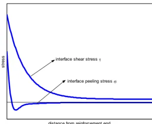
(1)P Delamination strength is conventionally computed evaluating the maximum stresses (peeling and shear) in the adhesive layer through a linear elastic analysis. Figure 6-3 shows the qualitative behaviour of the peeling and shear stress at the strengthening end.
distance from reinforcement end
st
re
ss interface shear stress W
interface peeling stress V
(2)P The main assumptions of the stress based approach are:
x cross section of the strengthening element remains plane;
x shear strain in the metallic beam and strengthening is neglected;
x perfect bond between different materials;
x linear-elastic stress-strain relationships;
x constant shear and peeling stresses through the thickness of the adhesive layer.
(3)P The shear stresses in the adhesive layer are function of the lack-of-fit strain, ǻİfs, developing
between the metallic beam and the strengthening if no adhesive joint was present. The peeling
stresses are function of the lack-of-fit curvature, ǻȤfs, developing between the metallic beam and the
strengthening if no adhesive joint was present. The lack-of-fit strain and curvature can be evaluated as follows:
fs fa,t fa,0 sa,t sa,0 fs f,t f,0 s,t s,0 'H H H H H 'F F F F F , (4.1) where:
-İfa,t is the longitudinal strain at the adhesive-FRP interface after the adhesive joint setup;
-İsa,t is the equivalent longitudinal strain at the metal-adhesive interface;
-İfa,0 is the longitudinal strain at the adhesive-FRP interface at the adhesive joint setup (t = 0);
-İsa,0 is the equivalent longitudinal strain at the metal-adhesive interface at the adhesive joint setup
(t = 0);
-Ȥf,t is the bending curvature in the strengthening after the adhesive joint setup;
-Ȥs,t is the equivalent bending curvature in the metallic beam;
-Ȥf,0 is the bending curvature in the strengthening at the adhesive joint setup (t = 0);
-Ȥs,0 is the equivalent bending curvature in the metallic beam at the adhesive joint setup (t = 0).
The above quantities must be evaluated under the assumption that no adhesive joint is present between the beam and the reinforcement.
(4) The subscript “0” is used for strains and curvatures developing at the time of adhesive joint
setup. They are due to the loads applied before the adhesive joint setup or to other initial strains (prestrain). For instance, in a metallic beam prestrain can be due to the precambering produced by props or jacks. In a pultruded strip prestarin can be applied by a pretension prior to bonding. Similarly, after the formation of the adhesive joint, the longitudinal strain and the bending curvature in the substrate must be evaluated in relation to the total applied loads and, eventually, to the temperature change. With reference to the strengthening, the relevant quantities are simply due to the prestrain applied to the composite.
6.2.1 Evaluation of shear stresses in the adhesive layer
(1)P At a stress discontinuity, the lack-of-fit strain, ǻİfs, can be approximated by the following
linear expression:
fs x 0 1 x
'H 'H 'H , (4.2)
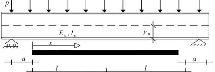
(2) For a beam strengthened with FRP on the tensile side (Figure 6-4), assuming, for the sake of
simplicity, that the metallic beam is unstressed at the time of strengthening (Hsa,0 = 0) and no other
strains are applied to the reinforcement at the time t = 0 (Hfa,0 = 0) and after the adhesive joint setup
(Hfa,t = 0), 'H0 e 'H1 are evaluated as follow:
0 s s s s s s (0) 2 a p a l M y y E I E I ' 'H § · ¨ ¸ © ¹ , (4.3) 1 s s s s s s (0) ( ) T x p l x y y E I E I ' 'H , (4.4)
where 'M(0) and 'T(0) are, respectively, the change of bending moment and shear force at x = 0
after the adhesive joint setup (in the present example they are equal to the total applied loading); p,
a,l are showed in Figure 6-4; Es and Is are the modulus of elasticity and the moment of inertia of
the metallic beam, respectively; ys is the distance of the centroid of the beam from the adhesive
interface (Figure 6-4). Note that the above differences were evaluated by a linear approximation of
the bending moment 'M x in the substrate close to the stress discontinuity and then assuming:
0 0
M x M T x
' ' ' . (4.5)
If non linear bending moment is present, the above approximation does not lead to significant errors. In fact, stress concentrations are limited to a short distance close to the relevant discontinuity.
Es,Is ys l a p x l a
Figure 6-4 – Evaluation of ǻİfs for a metallic beam under a distributed load p and reinforced by an
FRP plate.
(3) In the case of a symmetrically strengthened metallic element subject to a tensile load P and a
temperature change ǻT (Figure 6-5), if the metallic beam is unstressed at the time of strengthening
(Hsa,0 = 0) and no strain is imposed to the strengthening at t = 0 (Hfa,0 = 0), then 'H0 and 'H1 are given
by:
0 f s f s s s s s (0) N P T T E A E A ' 'H D D ' D D ' , (4.6) 1 0 'H , (4.7)where Df and Ds are the thermal expansion coefficient of the composite and substrate respectively;
'N(0) is the axial load change in the steel element, at x = 0 after the adhesive joint setup (note that
in this case it is equal to the total applied load); As is the cross section of the metallic element.
s s, s E A, D
f f, f
E ,A D
P P
Figure 6-5 – Evaluation of ǻİfs for a tensile metallic element symmetrically strengthened and
subject to an axial load P and a temperature change ǻT.
(4) The maximum value of the shear stress in the adhesive layer (at x = 0), Wmax, is evaluated by
the following expression:
0 1 max f f 2 2 1 (0) N b f f 'H 'H W ª«§¨' ·¸ O º» © ¹ ¬ ¼ , (4.8) where: 1 2 f f O , (4.9) a 1 a f t f G b § · ¨ ¸ © ¹ , (4.10)
- for a metallic beam strengthened on the tensile side: 2 f f s s s s ( 2 ) 1 1 ys tf ta ys f E A E A E I § · ¨ ¸ © ¹ ; (4.11)
- for a tensile element symmetrically strengthened:
2 f f s s 1 2 f E A E A § · ¨ ¸ © ¹ ; (4.12) where:
- bf is the strengthening width;
- ta is the adhesive thickness;
- tf is the strengthening thickness;
- Ga is the adhesive shear modulus;
- Ef and Af, are the modulus of elasticity and the cross section area of the strengthening,
respectively;
- Es,As, Isand ys are the quantities above defined.
The quantity 'Nf(0) in eq. (4.8) is the axial load change in the composite at the discontinuity (x =
0) and it is function of the discontinuity type (Figure 6-1). As an example, without an external load
applied directly to the strengthening end, one has: 'Nf(0)=0.
6.2.2 Peeling stress evaluation in the adhesive layer
(1)P The curvature lack-of-fit, ǻȤfs, can be evaluated from eq. (4.5), as follows:
fs x 0 1 x
'F 'F 'F . (4.13)
(2)P The maximum value of the peeling stress in the adhesive layer (at x = 0), Vmax, is evaluated
by the following expression:
2 2 3 1 max 4 4 f 1 2 1 2 a C C b a a O V E O ª º « » ¬ ¼ , (4.14) where: a 1 a f t a E b , (4.15) 2 f f s s 1 1 a E I E I , (4.16) 3 f f s s ( 2 ) f s f a f y y t t y a E I E I , (4.17)