Copper selenide
fi
lm electrodes prepared by combined
electrochemical/chemical bath depositions with high
photo-electrochemical conversion ef
fi
ciency and stability
Ahed Zyoud
a, Khaled Murtada
a, Hansang Kwon
b, Hyun-Jong Choi
c, Tae Woo Kim
c,
Mohammed H.S. Helal
d, Maryam Faroun
e, Heba Bsharat
f, DaeHoon Park
g,
Hikmat S. Hilal
a,*aSSERL, Chemistry, An-Najah National University, Nablus, Palestine
bDepartment of Materials System Engineering, Pukyong National University, 365 Sinseonro, Namgu, 608-739, Busan, Republic of Korea cEnergy Materials Laboratory, Korea Institute of Energy Research, 152 Gajeong-Ro, Yuseong-Gu, Daejeon City 34129, Republic of Korea dDepartment of Electrical&Computer Engineering, NCTU, (ED111) 1001 Ta Hsueh Road, Hsinchu 30010, Taiwan, ROC
eAl-Quds University, Abu Dies-Al-Quds, Palestine
fDepartment of Physics and Engineering Physics, College of Arts and Science, University of Saskatchewan, 116 Science Place, Saskatoon S7N 5E2, Canada gSutaek-Dong 1f, 50, Gyeongchun-Ro 276Beon-gil, Guri-Si, Gyeonggi-Do, Republic of Korea
a r t i c l e i n f o
Article history:
Received 19 October 2017 Received in revised form 16 November 2017 Accepted 29 November 2017 Available online 5 December 2017 Keywords:
Copper selenidefilms
Combined electrochemical&chemical bath depositions
PEC
Enhanced stability and conversion efficiency
a b s t r a c t
Copper selenide (of the type Cu2-xSe)film electrodes, prepared by combined electrochemical (ECD) followed by chemical bath deposition (CBD), may yield high photo-electrochemical (PEC) conversion efficiency (~14.6%) with no further treatment. The new ECD/CBD-copper selenidefilm electrodes show enhanced PEC characteristics and exhibit high stability under PEC conditions, compared to the ECD or the CBDfilms deposited separately. The electrodes combine the advantages of both ECD-copper selenide electrodes (in terms of good adherence to FTO surface and high surface uniformity) and CBD-copper selenide electrodes (suitable film thickness). Effect of annealing temperature, on the ECD/CBD film electrode composition and efficiency, is discussed.
©2017 Elsevier Masson SAS. All rights reserved.
1. Introduction
Photovoltaic (PV) devices, based on homo-junctions and tan-dem cells, now exhibit high conversion efficiency values of 30% or higher[1]. Despite that, PV systems demand high manufacturing costs and special preparation conditions. Thinfilm electrodes are emerging as alternative to the costly p-n junction (PV) systems [2e4]. Photo-electrochemical (PEC) processes based on poly-crystalline metal chalcogenide (MX, where M¼Zn, Cd or Cu; X¼S, Se or Te) electrodes are being considered, due to their ease of preparation, low thickness, economic demand for starting chemical amounts and low environmental impact[5,6]. However, suchfilm electrodes, based on polycrystalline MX materials, suffer serious
shortcomings, namely their poor conversion efficiencies and low stabilities. In recent reports, Cu2Tefilms show a maximum con-version efficiency of 5.35% while CuSefilms show 4.94% conversion efficiency [7e9]. In another recent review, CdSe film electrodes exhibit only 1.6% conversion efficiency[10]. Low stability under PEC conditions is also observed for MX film electrodes [11]. The ex-pected conversion efficiency for pristine thinfilm electrodes for 2020, based on US-DOE announcements, is less than 15%. Enhancing efficiency and stability of suchfilm electrodes is thus imperative[12].
With a band gap range 2.1e2.3 eV and high absorptivity, copper selenidefilm electrodes are promising candidates for PEC purposes [13]. Suchfilms have been investigated, but their PEC behavior has not been widely reported in their pristine form. Unlike their mixed ternary and quaternary systems[14], which show conversion effi -ciency values higher than 15%, the pristine systems show only low conversion values, vide supra. For example, copper selenidefilms *Corresponding author.
E-mail addresses:hshilal@najah.edu,hikmathilal@yahoo.com(H.S. Hilal).
Contents lists available atScienceDirect
Solid State Sciences
j o u r n a l h o m e p a g e :w w w . e l s e v i e r . c o m /l ocate/ ss sc ie
https://doi.org/10.1016/j.solidstatesciences.2017.11.013 1293-2558/©2017 Elsevier Masson SAS. All rights reserved.
prepared by chemical bath deposition (CBD) showed relatively low conversion efficiencies [2,15]. Electrochemically deposited (ECD) CuSefilm electrodes have not been widely reported for PEC pur-poses, presumably due to their thickness limitations.
In a recent report, both conversion efficiency and stability of CuSe film electrodes have been enhanced by coating them with electro-active materials embedded inside polymeric matrices. Conversion efficiency and stability have been enhanced due to charge transfer catalytic behavior of the electro-active materials. The untreated (pristine) CuSefilms showed only 1.2% efficiency[16]. This work aims at preparing copper selenide film electrodes with relatively high PEC efficiency and stability, with no additional treatment. The technique involves a combination of the two known simple ECD and CBD methods together to yield ECD/CBD film electrodes. Both ECD and CBD methods are non-costly, facile and demand no advanced techniques of ultra-high vacuum. Such a combined technique has been successfully described here for CdSe [17]and for CdSfilms[3]. In this technique, a thin uniform layer is deposited onto conducting glass/FTO substrates by ECD, followed by a thickerfilm deposition by CBD. The resulting ECD/CBD-CuSe film is assumed to combine the advantages of both ECD and CBD preparations together. While the ECD method yields highly uniform films of good contact with the FTO surface[18], the CBD method yieldsfilms with higher thicknesses that are more suitable for PEC purposes[19e21]but have the shortcoming of lower adherence to the substrate surface [22]. Earlier ECD/CBD-CdS film electrode showed efficiency value of 0.29%[3]compared to 0.049% observed for their CBD counterpart[23]. The ECD/CBD-CdSefilm exhibited ~4.4% efficiency even with no additional treatment[17]compared to 0.8% for the CBD counterpart[24]. The main goal of this work is to check if pristine ECD/CBD-copper selenidefilm electrodes exhibit enhancement in their PEC efficiency compared tofilms prepared by either ECD or CBD separately, for thefirst time. The strategy is to reach conversion efficiency values, of ~15%, which have recently been reported for coated copper selenide film electrodes [25], without the necessity of any further electrode treatments described earlier[26e28]. The as-depositedfilm performance enhancement is thus the major goal to start with in this work. The as-prepared ECD/ CBDfilms will be prepared, characterized and examined in PEC processes, without being annealed. For comparison purposes, samples will be annealed at relatively high (250C) just to check for any annealing effect at this stage. Effect of annealing on film composition, surface morphology and PEC efficiency will be assessed here. Future study will follow on the ECD/CBD systems, to study the effect of annealing at a wide range of temperatures, together with effect of coating by electro-active species.
2. Experimental
2.1. Starting materials
All starting materials were purchased from Merck, Fluka or Aldrich in pure form. FTO/glass substrates (Aldrich) were highly transparent (80%) for radiations with longer than 330 nm. The substrate resistivity was ~7.0
U
/sq.The Na2SeSO3(source for Se ions) was prepared as described in literature [22]. Na2SO3 (20.00 g) and selenium powder (2.00 g) were added to distilled water (100 mL). The mixture was contin-uously stirred for 10 h at 80C. The mixture was thenfiltered and the Na2SeSO3solution was carefully stored in a stoppered bottle in the dark.
2.2. Equipment
Solid state electronic absorption (EA) spectra (200e800 nm
range) were measured for different CuSefilms using a Schimadzu UV-1601 spectrophotometer. For photoluminescence (PL) spectral measurement, a Perkin-Elmer LS 50 spectrometer was used with excitation wavelength 383 nm while excluding all 400 nm (and shorter) wavelengths from the detector. Atomic force microscopy (AFM) was performed on a tapping mode system equipped with a WSxM software (Nanotech Electronica, Spain), at Al-Quds Univer-sity-AbuDies. Non-conductive rectangular Si3N4 cantilevers (NSG10, NT MDT Co.) having spring constants 55.5e22.5 N/m and reference frequency range 190e325 kHz were used.
Scanning electronic micrographs (SEM) and electron dispersion X-ray (EDX) spectra were measured on a Hitachi Model S-4300 Field Emission Scanning Electron Microscope in Korean Institute of Energy Research, Korea. X-ray diffraction (XRD) patterns were measured on PANalytical X'Pert PRO X-ray diffractometer using a CuKa source (
l
¼1.5418 Å) at Pukyong National University, Korea. A PAR 263A Potentiostat/Galvanostat was used to measure current density v. potential (J-V) plots.2.3. Film preparation
All FTO/glass substrates (4 1 cm2) were pre-cleaned by a washing-up detergent and distilled water, followed by soaking in HCl (10%V/V) for 60 min. The substrates were then rinsed with distilled water for many times to remove the acid.
The ECD preparation was performed as follows [16]: The aqueous Na2SeSO3 solution (20.0 mL, 0.08 M) was mixed with aqueous solution of CuSO4(20.0 mL, 0.008 M) and NH4Cl solution (10 mL, 3.0 M) while bubbling a stream of nitrogen (99.999%) through an inlet. The nitrogenflow was then continued above the solution during deposition to prevent contamination with air. ECD was performed at room temperature using the DC stripping at a constant potential (0.6 V vs. Ag/AgCl) for the glass/FTO electrode. A pre-cleaned platinum sheet was used as a counter electrode. All films prepared by ECD are termed as ECDfilms. Current vs. time plots during ECDfilm preparation were measured and showed that the current decreased with time, due to increased cross sectional resistance (across the film) by increasing film thickness. After 15 min deposition, the film thickness was calculated using the Faraday law to be in the range 700e800 nm, assuming the density for copper selenide is 6.0 g/cm3 [29] in accordance with earlier reports [16]. The gravimetrically measured ECD film thickness (550±20 nm) resembled those reported earlier[30,31]. The cross sectional SEM measured thickness was in the range 700e750 nm. The average film sheet resistivity value, measured as described earlier[16], was ~2.5104
U
cm.The CBD preparation was performed, as described earlier[31] with amendments, as follows: Solutions of CuSO4(4.0 mL, 0.5 M), Na3C6H5O7(4.0 mL, 0.1 M), Na2SeSO3(4.0 mL, 0.25 M) were mixed with a few drops of HCl (dilute) and distilled water to make the total solution volume 50 mL and pH ~6.5. The Glass/FTO substrates were dipped inside the solution at room temperature with gentle stirring for different deposition times (2, 4 and 6 h). The CBDfilms were then taken, rinsed with distilled water and dried. The gravi-metrically measured thickness was in the range 40e45
m
m, for films deposited in 2 h. Unless otherwise stated, thefilms deposited in 2 h were considered in this work as they have better PEC char-acteristics. The average film sheet resistivity, measured as described earlier[16], was ~1.0104U
cm. The choice for depo-sition time was not arbitrary. Copper selenidefilms were prepared using similar methods at 60C throughout a deposition time of 1 h [31]. In this work CBD deposition at room temperature is inten-tionally chosen, as described in preparing ECD/CBD film below. Room temperature deposition of CBD films has been reported earlier using a relatively long time of 4 h[22]. In order to optimizedeposition time here, while using room temperature, different deposition times (2, 4 and 6 h) were examined. Depositions in shorter time (1 h or less) were examined at room temperature but yieldedfilms which were difficult to characterize here and were disregarded here.
To prepare ECD/CBDfilms, the room temperature CBD proced-ure described above was followed using ECDfilms in place of the glass/FTO substrates. Room temperature was intentionally used here to avoid affecting the ECD layer (which is originally deposited at room temperature) by any heating. The CBD was continued for 2 h as described above. The gravimetrically measured ECD/CBDfilm thickness value was in the range 46e52
m
m, which is slightly more than the sum of ECD and CBD layer thicknesses separately. The averagefilm sheet resistivity was ~0.8104U
cm. The as-prepared film electrodes were used in PEC study here with no annealing. Effect of annealing onfilm composition, uniformity and PEC char-acteristics was then investigated afterwards.Film annealing was performed under a stream of nitrogen gas (99.999%) in a thermostated horizontal tube furnace. The films were placed inside a glass cylinder which was then placed in the furnace after the setting temperature (250C) was reached, for 60 min. The resultingfilms were cooled either by slow cooling (within 3 h) or by fast cooling (in less than 5 min).
2.4. The PEC experiment
The copper selenidefilms were used as working electrodes, and a pre-cleaned platinum sheet was used as a counter and a reference electrode. The PEC experiments were thus conducted in a stop-pered two-electrode cell. The internal cell (connected with the counter electrode) was pre-calibrated with Ag/AgCl reference electrode and resembled NHE reference. All PEC results shown here are thus measured with reference to NHE unless otherwise stated. To prevent contamination, nitrogen (99.999%) was bubbled inside the aqueous solution of [K3Fe(CN)6 (0.1 M)/K4Fe(CN)6 (0.1 M)/ LiClO4(0.1 M)] for 5 min, and theflow was then continued above the solution throughout measurements.
Dark experiments were conducted under a thick black cloth, while photo-experiments were conducted under a solar simulator light (50 W tungsten-halogen lamp). The measured radiation in-tensity at the electrode surface was AM 38 solar spectrum (~0.002 W/cm2). The low intensity radiation was intentionally cho-sen to avoid any rise in experimental temperature. For extra pre-caution, the PEC cell was dipped in a circulated water bath at constant room temperature. Current density vs. potential (J-V) plots were measured vs. NHE, using a PAR 263A Potentiostat-Galvanostat, by dividing the total current (I-V) plots by the exposed electrode area. Electrode stability was measured using a Polarographic Analyzer (Pol 150) with an MDE 150 stand. Values of short circuit current density (JSC) were measured vs. time while keeping the electrode under constant low illumination intensity to avoid cell heating.
3. Results and discussions
In this work, three types of copper selenidefilms were prepared as described above. ECD-CuSe, CBD-CuSe and combined ECD/CBD-CuSefilm electrodes were all prepared. The as-prepared three types offilms were characterized by different methods and examined in PEC study, with no pre-annealing, for the reasons discussed above. The results are comparatively studied here. The present results are first shown for the as-depositedfilm electrodes. Effect of annealing on copper selenidefilm composition, surface uniformity and PEC efficiency is then discussed. The annealing study is restricted to one relatively high temperature (250C) just to check if it has any effect
on the electrode PEC performance. 3.1. Electronic absorption (EA) spectra
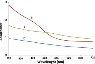
Solid state electronic absorption (EA) spectra were measured for the three copper selenidefilms, using FTO/Glass sheets for base line correction, as shown inFig. 1. The EA spectra cannot rule out the possibility of mixed copper selenide phases. The ECD/CBD film spectrum shows better defined absorption band compared to the ECD and CBD films. The Tauc plots were used for better under-standing of the spectra, as shown inFig. 2.
The ECD films were prepared using the optimal conditions (15 min deposition at room temperature) described earlier [16]. Due to its ill-defined EA spectrum, the direct band gap value (2.30 ± 0.20 eV) is difficult to measure accurately by the Tauc method. The CBDfilm prepared in 2 h showed only slightly smaller band gap value ranging (2.25±0.20 eV). The ECD/CBDfilm showed a smaller band gap value of 2.20 eV, as shown inFig. 2. The EA spectra imply that the combined ECD/CBD method yields particles with larger sizes than CBD method, which in turn involves slightly larger particles than the ECD particles. Metal chalcogenide nano-particles may vary with deposition method [18]. In the nano-scale, larger particles have lower relative surface area and lower numbers of coordinatively unsaturated surface atoms [32,33]. However, the differences in band gap values are too small to give final answer for particle sizes. The difference in band gap value may thus be due to the difference infilm thickness, which is known to affect value of band gap for nano-scale particles[34,35]. This con-firms thefilm thickness variations being ECD/CBD>CBD>ECD.
The CuSefilms have a wide range of band gap values in litera-ture. In some reports, the value is 2.13 eV[13], while in another report it was much smaller than that[28]. Khomane showed that the band gap value for Cu2-xSe is ~2.2 eV[26], while Liu observed a value of 1.34 eV [36]. Based on literature, CuSe films may have different values depending on method of preparation, particle size, phase purity and other factors. Direct bad gap values in the range 2.0e2.4 eV or higher have been reported[37e39]. All direct band gap values observed here are thus consistent with reported ones for CuSe and Cu2-xSe systems. Considering the value for bulk mono-crystalline copper selenide is ~1.05 eV, nano-size particles should exhibit higher band gap values[40].
3.2. Photoluminescence (PL) spectra
Fig. 3shows the PL emission spectra measured for ECD-,
CBD-Fig. 1.Electronic absorption spectra for CBD of the CuSe thinfilms, deposited in different techniques, a) CBD/ECD, b) CBD and c) ECD.
and combined ECD/CBD-CuSefilms. Due to its lower thickness, the ECDfilm shows lower emission band intensity than either CBD or ECD/CBD films. The three films show similar emission band wavelengths which makes it difficult to make conclusions about the band gap value differences[40]. Consistent with EA spectra, the PL emission spectra suggest the possibility of the presence of copper selenide, presumably in mixed phases. Further confi rma-tions, for copper selenide presence, are discussed below.
3.3. Surface morphology
SEM micrographs for the ECD, CBD and ECD/CBD films are shown inFig. 4. The Figure shows that differentfilms have different surface morphologies. The ECD/CBDfilm shows layered structure withflaky agglomerates. The agglomerates involve nano-size par-ticles as described by XRD below. The CBDfilm resembles that re-ported for other CBD-CuSefilms in its morphology[26,39]. The ECD film micrographs resemble earlier reported ones for ECD prepared films[16]as nano-size particles exist in larger agglomerates with some rod shape.
The AFM shows that the ECDfilm has higher uniformity and homogeneity than otherfilms,Fig. 5.Fig. 5A and 5B show that the ECDfilm involves higher interconnection between different parti-cles, than the CBDfilm, and to a lesser extent the ECD/CBDfilm. The AFM results confirm the assumption stated above about higher uniformity advantage of ECDfilms. The profile scanning (Fig. 5C), shows that ~95% of the surface elevations range between 10 and 120 nm. The CBDfilm has less uniformity (with ~95% elevations in a wide range of 10e200 nm) than the ECDfilm. ECD/CBDfilm shows ~95% elevations in the range 75e225 nm. The AFM micrographs for the CBDfilm resemble those reported earlier[39]. As the EA and PL spectra could not provide a clue to differentiate between different films in terms of band gap values, the surface morphology gives a clue of differences. Among the three differentfilms, the ECDfilm exhibits highest surface uniformity in terms of narrow profile dis-tribution range (110 nm) and high interconnectivity. The ECD/CBD film shows higher uniformity (with profile distribution range 150 nm) than the CBDfilm (with profile distribution range 190 nm).
3.4. XRD patterns
Fig. 6shows the XRD patterns for different copper selenide films. The Cu2-xSe characteristic peaks at 2ө ¼26.84 (111) and 44.4(220)[41]are observed, but they overlap with other peaks. The former peak overlaps with that for FTO, while the latter also overlaps with that for CuSe which may be present. EDX spectra further confirmed the occurrence of Cu2-xSe. The Cu/Se elemental atom ratios for ECD, CBD and ECD/CBDfilms are 1.01, 1.10 and 1.10 respectively. Allfilms show higher Cu than Se atomic presence, which confirms the presence of Cu2-xSe. The lower Cu/Se atom ratio for the ECD indicates the possibility of having higher CuSe phase than in the CBD or ECD/CBD.
The peaks at 2ө¼27.52, and 28.14and 32.00, attributed to CuSe hexagonal crystal structure[13,26,28,36,41e44], are observed clearly in the ECD film. The peak at 2ө ¼ 27.52 is not clearly observed in the CBD or ECD/CBDfilms, which means that the two films do not involve CuSe as a major component. This is consistent with EDX atom ratios discussed above.
Fig. 2.Tauc plots for CuSefilms prepared by different methods assuming a direct band gap. a) ECD b) CBD c) ECD/CBD.
Fig. 3.Photoluminescence spectra for CBD of CuSe thinfilms, deposited by different techniques, a) CBD/ECD, b) CBD, and c) ECD.
Thefilms do not involve the 29.1(200) peak characteristic for CuSe2[41]. Different FTO reflections are also observed in the Figure. The presence of CuO was not evidenced from the XRD patterns, but
it should not be totally excluded[37]. The occurrence of CuSe and Cu2-xSe phases, with band gap value ~2.2 eV reported for copper selenidefilms[26], can thus be justified by the XRD patterns. The XRD patterns clearly show that the materials are polycrystalline.
Calculations based on the Scherrer equation show that the average particle size varies for the films as ECD (25 nm), CBD (30 nm) and ECD/CBD (29 nm). The particle sizes for ECD and CBD films resemble those reported for other CuSefilms deposited by different methods[40]. The nano-size particles exist inside larger size agglomerates as explained by SEM and AFM micrographs above. The XRD results confirm the EA and PL spectral results dis-cussed above, as the ECDfilm involves only slightly smaller parti-cles. No significant effect on the value of the band gap is thus expected.
Based on XRD patterns, EA spectra and PL spectra, no signifi -cant differences occur between ECD, CBD and ECD/CBDfilms in terms of particle sizes or band gap values. Apart from the higher abundance of the CuSe phase in the ECDfilm, the only noticeable differences between the three films are the surface uniformity, inter-particle connectivity and depth profile variations which are in favor of the ECDfilm. The oncoming discussions will show how such variations may affect PEC performance of different film electrodes.
Fig. 5.AFM results for different copper selenidefilms, (a) 2-dimensional micrographs, (b) 3-dimensional micrographs, and (c) surface topographical distribution.
Fig. 6.XRD patterns measured for different CuSefilm preparations: (a) ECD, (b) CBD and (c) ECD/CBD.
3.5. PEC study
3.5.1. Dark current experiments
Dark current density (J) vs. applied potential (V) plots were measured for all three ECD, CBD and ECD/CBDfilm electrodes in aqueous media using the [Fe(CN)6]4-/Fe(CN)6]3-redox couple. The redox couple system was chosen based on earlier studies made for ECD-CuSe electrodes [16]. Negative dark current values were observed for all electrodes at negative applied potentials, as shown inFig. 7. The darkJ-Vplots thus indicate negative values for the onset potential in the dark. The electrode darkJ-Vplots are typical for n-type semiconducting materials. This should be expected due to the presence of Cu2Se (with Cuþ) phase in thefilms. As per CuSe phase itself, it is known have p-type nature[36]. Therefore, the n-type behavior of thefilms supports the XRD discussions showing Cu2-xSe (with excess Cu) is a major phase. Similar behaviors have been reported for naked and coated CuSe electrodes with some leakage currents [16]. The Figure shows that the ECD/CBD-CuSe electrode exhibited higher (more negative) onset potential than other counterparts.
3.5.2. 2: photo current experiments
PhotoJ-Vplots measured for different CuSefilm electrodes are shown inFig. 8. Both ECD and CBD electrodes showed poor short circuit current density (JSC) and open circuit potential (VOC) values. The ECD/CBD electrode showed higher PEC characteristics than other counterparts.
The Figure shows that allfilms exhibited n-type nature, as they all showed negativeVOCand positiveJSCvalues. Earlier literature shows that CuSe phase has high p-type conductivity with low band gap values[13,26,28,36]. The p-type nature of the CuSefilms was explained by Riha[37]. Another study showed that the CuSe elec-trodes exhibited an n-type behavior as observed from Mott-Schottky plots[45]. Such differences are attributed to the mixed phases in the preparedfilms, depending on the presence of Cu2þ and/or Cuþions. The Cuþions (in the predominant Cu2-xSe phase) should thus behave as electron donors in thefilms, which in turn should assume n-type behavior.
The PEC results of the Figure are summarized inTable 1below. The Table shows low photo-conversion efficiency (PCE,
h
%) values for ECD electrode (0.42%) and CBD electrode (1.83%) whereas theECD/CBD electrode exhibited higher PCE value (14.6%). The low value for the ECDfilm electrode resembled that observed earlier for ECD-CuSe electrodes[16]. The high abundance of CuSe, besides Cu2-xSe in the ECDfilm could be a reason. The Table shows also that all electrodes exhibited relatively lowfill factor (FF) as reported earlier for CuSe electrodes [16,45]. Despite the enhanced PEC characteristics (J-Vcharacteristics and conversion efficiency value) for the ECD/CBD electrode, the FF value is still relatively low. This is known for metal chalcogenide film electrodes. The presence of mixed phases could be a reason for the low FF value in copper selenidefilm electrodes. Fortunately, the FF value observed here is much higher than those reported earlier for different binary metal chalcogenidefilm electrodes[10,46]. In order to further improve FF and consequently the conversion efficiency, further modification of the ECD/CBDfilm electrode should be examined.
The PEC data shown inTable 1clearly indicate that the ECD/CBD electrode had much higher conversion efficiency than the ECD and the CBD counterparts, studied here or earlier reported. Similar observations were reported for ECD/CBD prepared CdSe[17]and CdS[3]electrodes. In all cases, the ECD/CBD exhibited much higher efficiency than the ECD and the CBD counterparts. Moreover, the ECD/CBD electrode showed conversion efficiency more than 100 fold that other earlier described for CuSe electrodes[45].
Based on the present results, and earlier reports, the preparation method may affect the PEC characteristics of metal chalcogenide film electrodes. The assumption mentioned in Section 1 above works well for CdSe[17], CdS[3]and copper selenide in this work. Successively combining the ECD and CBD preparations together should yield films with preferred properties. The ECD film is assumed to have high uniformity and good adherence with the
Fig. 7.DarkJ-Vplots for different CuSefilm preparations: (a) ECD, (b) CBD and (c) ECD/ CBD.
All measurement were made at room temperature using [Fe(CN)6]4-/Fe(CN)6]3-redox couple, vs. NHE.
Fig. 8.PhotoJ-Vplots measured for different CuSefilm preparations: (a) ECD/CBD, (b) CBD and (c) ECD. All measurement were made at room temperature using [Fe(CN)6]4-/ Fe(CN)6]3-redox couple, vs. NHE.
Table 1
PEC characteristics measured for different copper selenidefilm electrodes. Entry Description Voc(V) Jsc(mA/cm2) ɳ%a FF%b Ref.
A CBD/ECD (2 h) 0.32 3.52 14.6 25.41 This work B CBD (2 h) 0.20 0.76 1.83 22.5 This work C ECD (15 min) 0.11 0.28 0.42 26.5 This work D ECD (15 min) 0.18 0.12 1.04 28 [16]
E CuSec Small Small 0.11 28 [45] aɳ(%)¼[(maximum observed power density)/(reach-in power density)]100%. b FF¼[(maximum observed power density)/J
scVoc]100%.
c All measurement were made at room temperature using [Fe(CN)6]4-/Fe(CN)6] 3-redox couple, vs. NHE.
substrate FTO surface as documented earlier[17,18], which should enhance photocurrent across the copper selenide-FTO interface, as exhibited inTable 1above. The CBD preparation on the other hand yields thickerfilms that are more suitable for PEC purposes[20,21]. With a suitable thickness, the semiconductor film electrode can function more effectively in light to electricity conversion. The CBD film thickness was higher than that for the ECDfilm, which makes it more efficient in PEC processes, as documented for other CdSfilm electrodes[19,47]. Availability of higher CuSe phase in the ECDfilm could be another reason for lowering its efficiency compared to the CBDfilm. The fact that the ECD/CBD shows higher PEC performance is attributed to the poor adherence of the latter film with the substrate surface, as reported earlier[22].
In this work, the ECD exhibits higher uniformity and inter-particle connection than CBD, as discussed in Section3.3above, which enhances majority carrier mobility. The CBD layer has more suitable thickness which maximizes light absorptivity. The ECD/ CBDfilm electrode thus combines advantages of both ECD and CBD techniques, while avoiding the poor adherence of the copper selenide film to the substrate. To our knowledge, the efficiency value observed from the ECD/CBD-CuSe electrode here (14.6%) has not been preceded for pristine CuSefilm electrodes before. The results thus show the added value of combining different prepa-ration methods together in order to prepare highly efficient pristine metal chalcogenidefilm electrodes.
It should be noted that the PEC enhancement in ECD/CBDfilm efficiency is not due to the lower sheet resistivity compared to other ECD or CBD counterparts, as described in Section2.3. That is because in ECD/CBD, the lowering involves the sheet resistivity it-self not the cross sectional resistivity.
Further enhancement in the PEC characteristics of the ECD/CBD electrode has been examined. Deposition time for the CBD layer was varied, using 2, 4 and 6 h. Among the different deposition times used, the 2 h time was clearly the best, as discussed above. The maximum efficiency value for the CBD film varied with layer deposition time as: 2 h (1.83%)>4 h (0.90%)>6 h (0.40%). With longer deposition times, the CBD film becomes too thick with higher cross sectional resistance. Increased thickness for CBDfilms prepared from N,N-dimethylselenourea has been documented earlier[28]. Therefore, while using the combined ECD/CBD prepa-ration method, care was taken to use the optimal prepaprepa-ration time 2 h for the CBD layer.
3.5.3. Effect of annealing
Effect of pre-annealing the ECD/CBDfilm electrode on its PEC efficiency was examined. The results show that annealing the electrode at 250C or higher lowered its conversion efficiency, as shown inTable 2. Cooling rate also affected the film conversion efficiency. The Table shows efficiency lowering in the order: Non-annealed>>quickly cooled>slowly cooled.
In semi-conductor technology, annealing improves electrode PEC characteristics[16,25], while in some cases, annealing lowers the electrode performance [17]. Copper selenide film electrodes prepared by ECD exhibited efficiency lowering, while those pre-pared by CBD showed higher efficiency, by annealing at 250C[18]. The effect of annealing on ECD/CBD conversion efficiency is
investigated below, in parallel with XRD and EDX results.
Fig. 9shows the effect of annealing and cooling rate on XRD patterns for ECD/CBDfilms. InFig. 9b the especially high and sharp peak at ~ 29.10is due to the (200) reflection associated with a CuSe2[10,41,42,44]. The peak is much lower inFig. 9c, which im-plies that the peaks in the range 50 - 55refer to the FTO rather than to CuSe2 in the non-annealedfilm. InFig. 9a CuSe2 peaks appear in the quickly annealedfilm, but to a lesser extent than in Fig. 9b. The occurrence of the CuSe2(200) peak in case of slowly cooledfilm is due to the extra allowed time (3 h) for the heatedfilm to undergo phase transition. The presence of CuSe2phase in the annealed films is one possible reason for lowering PEC performance.
Fig. 9also shows that the non-annealed ECD/CBDfilm involves Cu2-xSe phase (2ө¼26.85) some CuSe phase (2ө¼27.35). Both ECD and CBD films involve higher CuSe phase than the non-annealedfilm. This is possibly another reason for the lowering in PEC performance for the annealedfilms.
EDX spectra,Fig. (S1), further confirm the XRD results.Table 3 summarizes elemental analysis for different film electrodes. The Table shows that the non-annealed ECD/CBDfilm involves highest atom ratio Cu/Se among the series. The Table also shows that the quickly cooledfilm has higher Cu/Se atom ratio than the slowly cooledfilm. In congruence with XRDfindings, prolonged exposure to heat in case of slowly cooledfilm is expected to have higher effect on the film composition. Lowering in Cu2-xSe phase by annealing, more obviously in the slow cooling, is one explanation for the negative effect of annealing on PEC performance.
Annealing also affectsfilm crystallinity. Values of XRD relative peak height (with respect to FTO peak at ~38) for different phases are summarized inTable 4. The non-annealedfilm has higher Cu 2-xSe/FTO peak ratio than the annealedfilms. The CuSe phase is also more available in the annealedfilms. The peak height ratio for Cu 2-xS/CuSe in different films varies as: non-annealed > slowly cooled>quickly cooled. The lower amount of the Cu2-xSe in the slowly cooled film, compared to the quickly cooled one, is ratio-nalized by the occurrence of CuSe2phase in the latter, as discussed above. This occurs at the expense of both CuSe and Cu2-xSe phases. The XRD and EDX results indicate that annealing has negative
Table 2
Effect of annealing (250C) and cooling rate on PEC characteristics of ECD/CBDfilm electrodes.
Entry Description Voc(V) Jsc(mA/cm2) ɳ% FF%
A Non-annealed 0.32 3.52 14.6 25.41 B Fast cooling 0.24 1.60 4.51 23.04
C Slow cooling 0.07 0.82 0.76 26.02 Fig. 9.XRD patterns measured for ECD/CBD-CuSefilms: (a) annealed and quickly cooled (b) annealed and slowly Cooled and (c) non-annealed.
effects on the ECD/CBDfilm crystallinity and composition. Such effects cause lowering in the PEC performance of the copper sele-nidefilm electrode, more obviously in case of slow cooling.
For better understanding of the effect of annealing and cooling rate on CuSefilm electrode PEC efficiency, the ECD and CBD elec-trodes were annealed at 250C, as shown inTable 5.
For the CBD electrode, efficiency increases by annealing and quick cooling (entries D&E). Slowly cooled CBD film exhibited efficiency lowering compared to non-annealed electrode (entries D
&E). The results are consistent with earlier reports, as CuSefilms are known to undergo degradation at higher temperatures [28]. The question that comes then is: why does the quickly annealed ECD/CBD film exhibit efficiency lowering, while the quickly annealed CBD film shows enhanced PEC efficiency? For the ECD film electrode, annealing lowers the conversion efficiency in both slow and quick cooling. The lowering in ECD/CBD electrode effi -ciency is thus attributed to the effect of annealing on the ECD layer. As the ECD layer, with high uniformity and adherence to FTO surface, becomes more disordered with higher phase mixing, by annealing, the ECD/CBDfilm electrode should then have lower PEC performance. On the other hand, the as-prepared CBD film is assumed to have high disorder and poor adherence with the FTO surface [22]. Annealing improves inter-particle connection and adherence with the FTO surface in case of CBD electrode, which enhances its PEC conversion efficiency. With slow cooling, exces-sive exposure to heat has a negative impact on thefilm electrode as shown inTable 5. Similar behaviors have been reported for ECD-and CBD-CdS electrodes[18].
A closer look at Table 5shows that quickly cooled ECD/CBD electrode gave higher conversion efficiency values than the slowly cooled counterpart. This is understandable, as the quickly cooled electrodes are exposed to high temperature for only shorter times than the slowly cooled counterparts. With longer exposure to heat, more disorder and more phase mixing occur in slowly cooledfilms, as described inTable 4. These results are rationalized by the ther-mal instability of copper selenidefilms as reported earlier[28,48]. Work is underway here to study effect of annealing the ECD/CBD copper selenide electrode at temperatures below 250 C, as
described earlier for different materials[16,25]. Effect of coating with electro-active composite materials, is also underway here, to further enhanceJ-Vcharacteristics, conversion efficiency, stability andfill factor[11,16,25].
3.5.4. Electrode stability under PEC conditions
The stability of the ECD, CBD and ECD/CBDfilm electrodes under PEC conditions was examined under constant light intensity, while using zero bias.Fig. 10shows that the ECD/CBD electrode exhibit higherJSCvalues, with time, than other counterparts. TheJSCvalues for both ECD- and CBD-CuSe electrodes do not reach a steady value even after time passes, and continue to decrease with time, which confirms the low stability of the electrodes under PEC conditions. This confirms the assumptions shown above. The ECD/CBD elec-trode exhibits a steadyJSCvalue (after ~30 min) with continued exposure to light with time, than other electrodes.
TheJSCvalues for ECD/CBD-CuSe electrode inFig. 10are lower than those measured for the same electrode in Fig. 8. This is because the stability experiments were performed under lower light intensity (less than 0.0004 W/cm2) than in J-V plot experiments.
The stability plots in the Figure show unsteadyJSCvalues at the beginning. In case of ECD/CBD the values start high and then go down until a steady value is attained after about 30 min. Similar behaviors have been observed for other metal chalcogenide metal electrodes[3,16,18]. The ECD and CBDfilms exhibit lowJSCvalues at the beginning, which increase to a certain limit and then continue to decrease. This is presumably due to the presence of
Table 3
EDX results measured for ECD/CBDfilms annealed at different temperatures.
Entry No. Film description Cu mass% Cu atom% Se mass% Se atom% Cu/Se atom ratio
A Quickly cooled 16.66 11.17 19.04 10.27 1.09
B Slowly cooled 22.23 17.52 33.09 20.99 0.83
C Non annealed 31.71 28.21 35.88 25.68 1.10
Table 4
Effect of annealing on value of XRD relative peak height for ECD/CBDfilms.
Entry number Film description Cu2-xSe (26.85)/FTO (~ 38) peak height ratio Cu2-xSe (26.85)/CuSe (27.35) peak height ratio
A Annealed&quickly cooled 0.71 2.13
B Annealed and slowly cooled 0.59 1.15
C Non-annealed 0.87 2.86
Table 5
Effect of annealing on conversion efficiency for ECD and CBD electrodes. Entry Preparation Description Efficiency%
A ECD Non-annealed 0.4 B Quickly cooled <0.4 C Slowly cooled <0.4 D CBD Non-annealed 1.83 E Quickly cooled 2.94 F Slowly cooled 0.23
Fig. 10.Film electrode stability, showing plots ofJSCvalue vs. time for different CuSe film preparations: (a) ECD, (b) CBD and (c) ECD/CBD. All measurement were made at room temperature using [Fe(CN)6]4-/Fe(CN)6]3-redox couple, vs. NHE.
contaminants at the surface of the electrode. As such contaminants are removed with time, higherJSCoccurs. Similar behaviors were reported earlier for metal chalcogenides film electrodes [11,16,18,25]. The continued lowering inJSCfor the ECD and CBD film electrodes is attributed to their lower stability to photo-corrosion. The Figure indicates that the ECD/CBD electrode has higher stability than the other counterparts with a steady value for JSCwith time. The ECD/CBDfilm stability is attributed to its higher JSC value, which means faster hole transfer at the solid liquid interface. This prevents hole accumulation in the space charge re-gion, which is responsible for film electrode photo-degradation (instability).
4. Conclusion
New copper selenide film electrodes, prepared by electro-chemical deposition followed by electro-chemical bath deposition, showed relatively high PEC conversion efficiency values (~14.6%) for te as-prepared film electrode. The new films also showed relatively high stability under PEC conditions. The enhanced PEC character-istics of the newfilms are attributed to their ability to combine the advantages of both electrochemically deposited and chemical bath depositedfilm electrodes. The results show how PEC properties of metal chalcogenide film electrodes can be enhanced by simple combined preparation techniques. Annealing at relatively high temperatures affects the film morphology and composition and lowers its PEC characteristics.
Acknowledgements
The results of this work arepartlybased on K. Murtada M.Sc. Thesis, under direct supervision of H.S. Hilal. Other experimental measurements and calculations, including dark current experi-ments,film thickness measurement, electrical conductivity, SEM analysis, XRD&AFM analysis revisions were performed by A. Zyoud after the thesis completion. Additionalfilm electrode stability ex-periments under PEC conditions, were also performed by A. Zyoud after the Thesis completion. SEM micrographs and EDX spectra were measured by T.W. Kim and H-J.C. at the KIER, Korea. The XRD patterns were measured by D-H. Park and H. Kwon at PUK. M.H.S. Helal and H. Bsharat contributed with literature search, discussions and modeling. M. Faroun measured AFM micrographs at Al-Quds University. H.S. Hilal acknowledges financial support from ANU, Islamic Development Bank, Al-Maqdisi Project and Union of Arab Universities. T.W. Kim and H-J. Choi acknowledgefinancial support from the framework of the Research and Development Program of the Korea Institute of Energy Research (B6-2523).
Appendix A. Supplementary data
Supplementary data related to this article can be found at https://doi.org/10.1016/j.solidstatesciences.2017.11.013.
References
[1] http://www.nrel.gov/ncpv/images/efficiency_chart.jpg.
[2] K. Chopra, P. Paulson, V. Dutta, Thin-film solar cells: an overview, Prog.
Pho-tovoltaics Res. Appl. 12 (2004) 69e92.
[3] A. Zyoud, I. Saadeddin, S. Khurduj, M.M. Mari’e, Z.M. Hawash, M.I. Faroun,
G. Campet, D. Park, H.S. Hilal, Combined electrochemical/chemical bath
de-positions to prepare CdSfilm electrodes with enhanced PEC characteristics,
J. Electroanal. Chem. 707 (2013) 117e121.
[4] N. Sabli, Z.A. Talib, W.M.M. Yunus, Z. Zainal, H.S. Hilal, M. Fujii, SnSe Thinfilm
electrodes prepared by vacuum evaporation: enhancement of
photo-electrochemical efficiency by argon gas condensation method,
Electrochem-istry 82 (2014) 25e30.
[5] B.M. Palve, V.S. Kadam, C.V. Jagtap, S.R. Jadkar, H.M. Pathan, A simple chemical
route to synthesis the CuSe and CuS counter electrodes for titanium oxide
based quantum dot solar cells, J. Mater. Sci. Mater. Electron. 28 (2017)
14394e14401.
[6] S. Thirumavalavan, K. Mani, S. Suresh, Structural, surface morphology, optical
and electrical investigation of cdse thinfilms, Chalcogenide Lett. 12 (2015)
237e246.
[7] F. Liu, J. Zhu, L. Hu, B. Zhang, J. Yao, M.K. Nazeeruddin, M. Gr€atzel, S. Dai,
Low-temperature, solution-deposited metal chalcogenidefilms as highly efficient
counter electrodes for sensitized solar cells, J. Mater. Chem. A 3 (2015)
6315e6323.
[8] G.W. Mudd, III-VI Metal Chalcogenide Semiconductor Nanosheets and
Het-erostructures, in, Ph.D. Thesis, University of Nottingham, 2016.
[9] C. Han, Synthesis of Nanostructured Metal Chalcogenides Used for Energy
Conversion and Storage, 2015.
[10] S.M. Ho, Metal chalcogenide thinfilms for photoelectrochemical cell
appli-cations: a Review, Middle-East J. Sci. Res. 24 (2016) 1232e1235.
[11] H. Sabri, S. Saleh, A. Zyoud, N.N. Abdel-Rahman, I. Saadeddin, G. Campet,
D. Park, M. Faroun, H.S. Hilal, Enhancement of CdSefilm electrode PEC
char-acteristics by metalloporphyrin/polysiloxane matrices, Electrochimica Acta
136 (2014) 138e145.
[12] K. Tyagi, B. Gahtori, S. Bathula, S. Auluck, A. Dhar, Band structure and transport
studies of copper selenide: an efficient thermoelectric material, Appl. Phys.
Lett. 105 (2014), 173905.
[13] J. Montes-Monsalve, R.B. Correa, A.P. Mora, Optical and structural study of
CuSe and CuSe/in thinfilms, J. Phys. Conf. Ser. (2014), 012024. IOP Publishing.
[14] M.A. Contreras, L.M. Mansfield, B. Egaas, J. Li, M. Romero, R. Noufi, E.
Rudiger-Voigt, W. Mannstadt, Improved energy conversion efficiency in wide bandgap
Cu (In, Ga) Se 2 solar cells, in: Photovoltaic Specialists Conference (PVSC),
2011 37th IEEE, IEEE, 2011, pp. 000026e000031.
[15] J.J. Scragg, P.J. Dale, D. Colombara, L.M. Peter, Thermodynamic aspects of the
synthesis of thin-film materials for solar cells, ChemPhysChem 13 (2012)
3035e3046.
[16] A. Zyoud, R.S. Al-Kerm, R.S. Al-Kerm, M. Waseem, H.H. Mohammed, D. Park,
G. Campet, N. Sabli, H.S. Hilal, High PEC conversion efficiencies from CuSefilm
electrodes modified with metalloporphyrin/polyethylene matrices,
Electro-chimica Acta 174 (2015) 472e479.
[17] A. Zyoud, N.N. Abdul-Rahman, G. Campet, D. Park, H. Kwon, T.W. Kim,
H.-J. Choi, M.H. Helal, H.S. Hilal, Enhanced PEC characteristics for CdSe
poly-crystallinefilm electrodes prepared by combined electrochemical/chemical
bath depositions, J. Electroanal. Chem. 774 (2016) 7e13.
[18] A. Zyoud, I. Saa'deddin, S. Khudruj, Z.M. Hawash, D. Park, G. Campet, H.S. Hilal,
CdS/FTO thinfilm electrodes deposited by chemical bath deposition and by
electrochemical deposition: a comparative assessment of
photo-electrochemical characteristics, Solid State Sci. 18 (2013) 83e90.
[19] S. Pawar, L. Deshmukh, Thickness dependent properties of
electro-chemical-photovoltaic (ecpv) cells formed with chemically deposited CdSfilms, Bull.
Mater. Sci. 7 (1985) 127e130.
[20] H.S. Hilal, R.M. Ismail, A. El-Hamouz, A. Zyoud, I. Saadeddin, Effect of cooling
rate of pre-annealed CdS thinfilm electrodes prepared by chemical bath
deposition: enhancement of photoelectrochemical characteristics,
Electro-chimica Acta 54 (2009) 3433e3440.
[21] A. Zyoud, N. Zaatar, I. Saadeddin, M.H. Helal, G. Campet, M. Hakim, D. Park,
H.S. Hilal, Alternative natural dyes in water purification: anthocyanin as TiO2
-sensitizer in methyl orange photo-degradation, Solid State Sci. 13 (2011)
1268e1275.
[22] B. Durdu, U. Alver, A. Kucukonder,O. S€ o€güt, M. Kavgaci, Investigation on zinc
selenide and copper selenide thinfilms produced by chemical bath
deposi-tion, Acta Phys. Pol. A 124 (2013) 41e45.
[23] M. Barote, A. Yadav, E. Masumdar, Synthesis, characterization and
photo-electrochemical properties of n-CdS thinfilms, Phys. B Condens. Matter 406
(2011) 1865e1871.
[24] R. Pandey, S. Mishra, S. Tiwari, P. Sahu, B. Chandra, Comparative study of
performance of CdTe, CdSe and CdS thinfilms-based photoelectrochemical
solar cells, Sol. Energy Mater. Sol. Cells 60 (2000) 59e72.
[25] A. Zyoud, R.S. AlKerm, R.S. Alkerm, D. Park, M.H. Helal, G. Campet,
R.W. Muthaffar, H. Kwon, H.S. Hilal, Enhanced PEC characteristics of
pre-annealed CuSfilm electrodes by metalloporphyrin/polymer matrices, Sol.
Energy Mater. Sol. Cells 144 (2016) 429e437.
[26] A. Khomane, Synthesis and characterization of chemically deposited Cu2-xSe
thinfilms, Archives Appl. Sci. Res. 4 (2012) 1857e1863.
[27] I. Ezenwa, N. Okereke, L. Okoli, Optical properties of copper selenide thin
films, Int. Res. J. Eng. Sci. Technol. Innovation 2 (2013) 82e87.
[28] C.A. Estrada, P. Nair, M. Nair, R.A. Zingaro, E.A. Meyers, Chemical bath
depo-sition of ZnSe and CuSe thin films using N, N-Dimethylselenourea,
J. Electrochem. Soc. 141 (1994) 802e806.
[29] http://www.guidechem.com/dictionary/en/1317-41-5.html.
[30] K. Ramesh, S. Thanikaikarasan, B. Bharathi, Structural, morphological and
optical properties of copper selenide thinfilms, Int. J. ChemTech Res. 6 (2014)
5408e5411.
[31] B. Pejova, I. Grozdanov, Chemical deposition and characterization of Cu3Se2
and CuSe thinfilms, J. Solid State Chem. 158 (2001) 49e54.
[32] B. Avinash, V. Chathurmukha, C. Naveen, M. Rajeeva, H. Jayanna, A.R. Lamani,
Influence of particle size on band gap and dielectric properties of TiO2
nanomaterials, in: International Conference on Condensed Matter and Applied Physics (ICC 2015): Proceeding of International Conference on Condensed Matter and Applied Physics, AIP Publishing, 2016, 020347.
[33] D. Segets, J.M. Lucas, R.N. Klupp Taylor, M. Scheele, H. Zheng, A.P. Alivisatos, W. Peukert, Determination of the quantum dot band gap dependence on particle size from optical absorbance and transmission electron microscopy
measurements, Acs Nano 6 (2012) 9021e9032.
[34] N. Das, P. Ghosh, M. Mitra, K. Chattopadhyay, Effect offilm thickness on the
energy band gap of nanocrystalline CdS thinfilms analyzed by spectroscopic
ellipsometry, Phys. E Low-dimensional Syst. Nanostructures 42 (2010)
2097e2102.
[35] J.-P. Xu, R.-J. Zhang, Y. Zhang, Z.-Y. Wang, L. Chen, Q.-H. Huang, H.-L. Lu,
S.-Y. Wang, S.-Y.-X. Zheng, L.-S.-Y. Chen, The thickness-dependent band gap and
defect features of ultrathin ZrO 2films studied by spectroscopic ellipsometry,
Phys. Chem. Chem. Phys. 18 (2016) 3316e3321.
[36] Y.-Q. Liu, F.-X. Wang, Y. Xiao, H.-D. Peng, H.-J. Zhong, Z.-H. Liu, G.-B. Pan, Facile
microwave-assisted synthesis of klockmannite CuSe nanosheets and their exceptional electrical properties, Sci. Rep. 4 (2014).
[37] S.C. Riha, D.C. Johnson, A.L. Prieto, Cu2Se nanoparticles with tunable electronic
properties due to a controlled solid-state phase transition driven by copper
oxidation and cationic conduction, J. Am. Chem. Soc. 133 (2010) 1383e1390.
[38] R.S. Mane, A.V. Shaikh, O.-S. Joo, S.-H. Han, H.M. Pathan, Electrodeposition of
copper selenidefilms from acidic bath and their properties, in: Indian Vacuum
Society Symposium on Thin Films: Science and Technology, AIP Publishing,
2012, pp. 194e196.
[39] S. Thirumavalavan, K. Mani, S. Sagadevan, Investigation of the structural,
optical and electrical properties of copper selenide thinfilms, Mater. Res. 18
(2015) 1000e1007.
[40] M.A. Malik, P. O'Brien, N. Revaprasadu, A novel route for the preparation of
CuSe and CuInSe 2 nanoparticles, Adv. Mater. 11 (1999) 1441e1444.
[41] M.-Z. Xue, Y.-N. Zhou, B. Zhang, L. Yu, H. Zhang, Z.-W. Fu, Fabrication and
electrochemical characterization of copper selenide thinfilms by pulsed laser
deposition, J. Electrochem. Soc. 153 (2006) A2262eA2268.
[42] Syed Ghause Ibrahim, Ashish V. Kadu, Physical and optical properties of
chemically deposited copper selenide (CuSe) thinfilms at room temperature,
Int. J. Innovative Res. Sci. Eng. Technol. 6 (2017) 365e368.
[43] V. Milman, B. Winkler, J.A. White, C.J. Pickard, M.C. Payne, E.V. Akhmatskaya,
R.H. Nobes, Electronic structure, properties, and phase stability of inorganic crystals: a pseudopotential plane-wave study, Int. J. Quantum Chem. 77
(2000) 895e910.
[44] K.-S. Kim, H.-C. Jeong, J.-Y. Cho, D.-H. Kang, H.-K. Kim, H.-M. Yoo, I.-W. Shim,
Preparation of copper (Cu) thinfilms by MOCVD and their conversion to
copper selenide (CuSe) thinfilms through selenium vapor deposition, Bull.
Korean Chem. Soc. 24 (2003) 647e649.
[45] K. Rathod, Synthesis, Characterization and Applications of Mixed
Chalco-genide Thin Films, Ph.D. Thesis, Aurangabad University, 2015.
[46] P.D. Matthews, P.D. McNaughter, D.J. Lewis, P. O'Brien, Shining a light on
transition metal chalcogenides for sustainable photovoltaics, Chem. Sci. 8
(2017) 4177e4187.
[47] J. Ximello-Quiebras, G. Contreras-Puente, J. Aguilar-Hernandez, G.
Santana-Rodriguez, A.A.-C. Readigos, Physical properties of chemical bath deposited
CdS thinfilms, Sol. Energy Mater. Sol. Cells 82 (2004) 263e268.
[48] S.D. Kang, J.-H. Pohls, U. Aydemir, P. Qiu, C.C. Stoumpos, R. Hanus, M.A. White,€
X. Shi, L. Chen, M.G. Kanatzidis, Enhanced stability and thermoelectricfi
gure-of-merit in copper selenide by lithium doping, Mater. Today Phys. 1 (2017)