Power Supply Modules
for AC Drives
DOK-POWER*GENEREL****-AUS1-EN-P
Selection and Dimensioning Manual
Rexroth
Indramat
261738
• DOK-POWER*GENEREL****-AUS1-EN-E1,44 • 10.96
Copyright
Validity
Published by
© INDRAMAT GmbH, 1994
Copying this document, and giving it to others and the use or communication of the contents thereof without express authority, are forbidden. Offenders are liable for the payment of damages. All rights are reserved in the event of the grant of a patent or the registration of a utility model or design (DIN 34-1) The electronic documentation (E-doc) may be copied as often as needed if such are to be used by the consumer for the purpose intended.
All rights are reserved with respect to the contents of this documentation and the availability of the product.
INDRAMAT GmbH • Bgm.-Dr.-Nebel-Straße 2 • D-97816 Lohr Telephone 09352/40-0 • Tx 689421 • Fax 09352/40-4885 Dept. ENA (DE, FS)
Title
Type of documentation
Documenttype
Internal file reference
Purpose of documen-tation
Power Supply Modules for AC Drives
Selection and Dimensioning Manual
DOK-POWER*-GENEREL****-AUS1-EN-E1,44 • 10.96
• Mappe 6 • Versg-AW.pdf • 209-0049-4301-01
This document is to be used for:
• Selecting power supply modules based on functional considerations • Selecting auxiliary components
• Calculating the data needed to make proper selections
• Selecting supply modules based on the performance requirements of individual drives
• Determining the line connection power
Designation of documentation Release- Comments up to present edition date
209-0049-4301-00 EN/09.94 Sep./94 First Edition
209-0049-4301-01 EN/03.95 Mär./95 Revision
DOK-POWER*-GENEREL****-AUS1-EN-E1,44 Okt./96 Introduction of document type
Table of Contents
1. Configuration of the Modular INDRAMAT AC Drive System 5
1.1. Function of the Power Supply Module ...5
2. Applications and Power Characteristics 6 2.1. Selection Data ...7
2.2. TVM 2.4 Power Supply Module ...9
2.3. TVD 1.2 Power Supply Module ...12
2.4. TVR 3.1 Power Supply Module ...15
2.5. KDV 2.3 Power Supply Module ...18
2.6. KDV 4.1 Power Supply Module ...22
2.7. KVR 1.2 Power Supply Module ...26
3. Calculations and Selecting the Correct Power Supply 30 3.1. DC Bus Continuous Power ... 31
3.2. DC Bus Peak Power ...34
3.3. Regenerated Energy ...34
3.4. Continuous Regenerated Power ...36
3.5. Peak Regenerated Power ...37
3.6. Power Requirements ...38
3.7. Power Requirements for Motor and Heat Sink Blowers ... 39
3.8. Power for the Electronic Circuits ...39
4. Index 41
5. Additional Documentation 43
1.
Configuration of the Modular
INDRAMAT AC Drive System
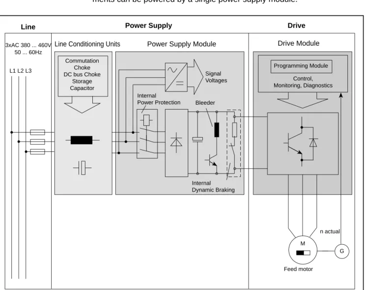
The modular INDRAMAT AC Drive System consists of the power supply module, the drives and the motors. Several drives of various power require-ments can be powered by a single power supply module.
3xAC 380 ... 460V 50 ... 60Hz L1 L2 L3
Line Power Supply Drive
Power Supply Module Drive Module
Internal Power Protection Internal Dynamic Braking Bleeder Signal Voltages Programming Module Control, Monitoring, Diagnostics M G n actual Feed motor Commutation Choke DC bus Choke Storage Capacitor
Line Conditioning Units
FSmodACVer
1.1. Function of the Power Supply Module
The power rectifier in the power supply module converts the AC line voltage and provides a DC bus voltage for supplying power to the drives. When the drives are operating as generators, the regenerated energy is either fed back into the electrical power system or it is absorbed by a bleeder resistor. The signal voltage is supplied to all the drives via a wire-ribbon cable. The power supply module is equipped with an extensive array of monitoring functions. It communicates with the drives by means of the wire-ribbon cable. In the event of trouble, the supply of power to the drives is cut off.
• DOK-POWER*GENEREL****-AUS1-EN-E1,44 • 10.96
2.
Applications and Power Characteristics
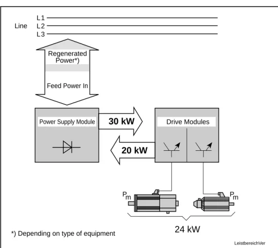
The power supply modules are designed to be operated with modular INDRAMAT AC drives. Modular AC drives can be used for continuous mechanical power requirements up to 24 kW. The appropriate power supply unit is available for all drive requirements within this power range.
Feed Power In
30 kW
20 kW
Pm Pm24 kW
LeistbereichVer Line L1 L2 L3Power Supply Module Drive Modules Regenerated
Power*)
*) Depending on type of equipment
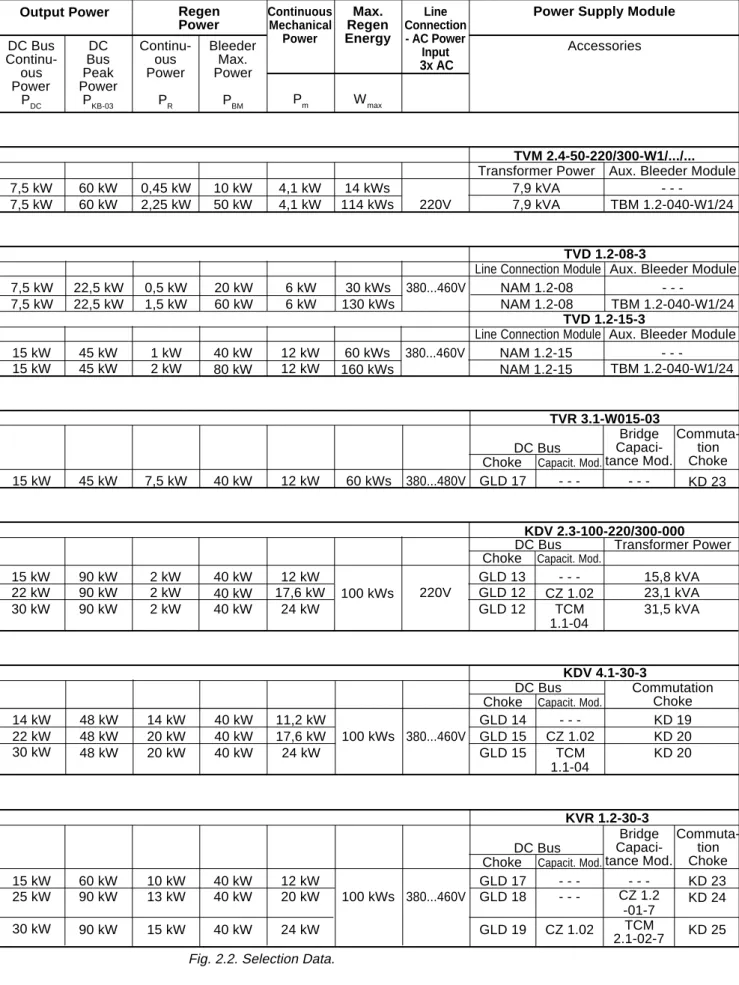
2.1. Selection Data
Continuous Mechanical Power Max. Regen Energy Line Connection - AC Power Input 3x ACPower Supply Module
Output Power Regen
Power DC Bus Continu-ous Power PDC DC Bus Peak Power PKB-03 Continu-ous Power PR Bleeder Max. Power PBM Pm Wmax Accessories 7,5 kW 7,5 kW 60 kW 60 kW 0,45 kW 2,25 kW 10 kW 50 kW 4,1 kW 4,1 kW 14 kWs 114 kWs 220V 7,9 kVA 7,9 kVA -TBM 1.2-040-W1/24 TVM 2.4-50-220/300-W1/.../...
Aux. Bleeder Module Transformer Power
TVD 1.2-08-3
Line Connection Module Aux. Bleeder Module 7,5 kW 7,5 kW 22,5 kW 22,5 kW 0,5 kW 1,5 kW 20 kW 60 kW 6 kW 6 kW 30 kWs 130 kWs 380...460V NAM 1.2-08 NAM 1.2-08 -TBM 1.2-040-W1/24 TVD 1.2-15-3
Line Connection Module Aux. Bleeder Module 15 kW 15 kW 45 kW 45 kW 1 kW 2 kW 40 kW 80 kW 12 kW 12 kW 60 kWs 160 kWs 380...460V NAM 1.2-15 NAM 1.2-15 -TBM 1.2-040-W1/24 15 kW 45 kW 7,5 kW 40 kW 12 kW 60 kWs 380...480V GLD 17 - - - KD 23 Choke Capacit. Mod.
DC Bus TVR 3.1-W015-03 15 kW 22 kW 30 kW 90 kW 90 kW 90 kW 2 kW 2 kW 2 kW 40 kW 40 kW 40 kW 12 kW 17,6 kW 24 kW 100 kWs 220V GLD 13 GLD 12 GLD 12 -CZ 1.02 TCM 1.1-04 15,8 kVA 23,1 kVA 31,5 kVA KDV 2.3-100-220/300-000
DC Bus Transformer Power Choke Capacit. Mod.
14 kW 22 kW 30 kW 48 kW 48 kW 48 kW 14 kW 20 kW 20 kW 40 kW 40 kW 40 kW 11,2 kW 17,6 kW 24 kW 100 kWs 380...460V GLD 14 GLD 15 GLD 15 -CZ 1.02 TCM 1.1-04 KD 19 KD 20 KD 20 KDV 4.1-30-3 DC Bus Commutation Choke Choke Capacit. Mod.
15 kW 25 kW 30 kW 60 kW 90 kW 90 kW 10 kW 13 kW 15 kW 40 kW 40 kW 40 kW 12 kW 20 kW 24 kW 100 kWs 380...460V GLD 17 GLD 18 GLD 19 -CZ 1.02 -CZ 1.2 -01-7 TCM 2.1-02-7 KD 23 KD 24 KD 25 Choke Capacit. Mod.
DC Bus
KVR 1.2-30-3
Fig. 2.2. Selection Data.
Commuta-tion Choke Bridge Capaci-tance Mod. Commuta-tion Choke Bridge Capaci-tance Mod.
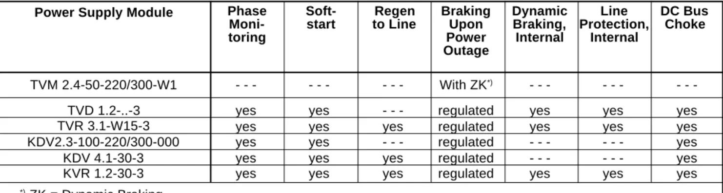
• DOK-POWER*GENEREL****-AUS1-EN-E1,44 • 10.96 Dynamic Braking, Internal Line Protection, Internal DC Bus Choke Braking Upon Power Outage Regen to Line Soft-start Phase Moni-toring Power Supply Module
TVM 2.4-50-220/300-W1 TVD 1.2-..-3 TVR 3.1-W15-3 KDV2.3-100-220/300-000 KDV 4.1-30-3 KVR 1.2-30-3 -yes yes yes yes yes -yes yes yes yes yes -yes -yes yes With ZK*) regulated regulated regulated regulated regulated -yes yes -yes -yes yes -yes -yes yes yes yes yes *) ZK = Dynamic Braking
Fig. 2.3. Functional characteristics of the supply modules. Overview of Functional
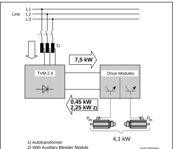
2.2. TVM 2.4 Power Supply Module
Modular power supply for more than one servo drive (typically 6)
7,5 kW
0,45 kW
2,25 kW
2) Pm EinbTVM24Ver Line L1 L2 L3 TVM 2.4 Drive Modules 1) Autotransformer2) With Auxiliary Bleeder Module 1)
Pm
4,1 kW
Application
Fig. 2.4. TVM 2.4 service range.
Continuous mechanical power: 4.1 kW
Line voltage: 3 x 220V AC (+/- 15%)
3 x 230V AC (+ 10% /- 15%)
DC bus continuous power: 7.5 kW
Continuous regen power: 450 W
2.25 kW with auxiliary bleeder module Dimensions 325 355 390 105 MBklTVM24Ver
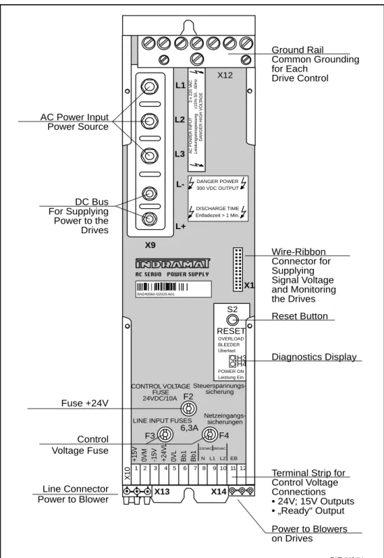
• DOK-POWER*GENEREL****-AUS1-EN-E1,44 • 10.96 Front View CONTROL VOLTAGE FUSE POWER SUPPLY AC SERVO SN240060-02029 A01 RESET S2 OVERLOAD BLEEDER Überlast H3 H4 POWER ON Leistung Ein F4 +15V 0VM -15V +24VL 0VL Bb1 Bb1 1 2 3 4 5 6 7 8 9 10 11 12 220VAC 380VAC N L1 L2 EB FATVM24Ver DANGER POWER 300 VDC OUTPUT DISCHARGE TIME Entladezeit > 1 Min. AC POWER INPUT 3 x 220 V A C
DANGER HIGH VOL
TAGE Leistungseinspeisung ± 15% 50…60Hz X9 L+ X1 Steuerspannungs-sicherung Netzeingangs-sicherungen 6,3A F3
LINE INPUT FUSES 24VDC/10A F2 X10 L-L3 L2 L1 X12 AC Power Input Power Source DC Bus For Supplying Power to the Drives Fuse +24V Control Voltage Fuse Line Connector Power to Blower Ground Rail Common Grounding for Each Drive Control Wire-Ribbon Connector for Supplying Signal Voltage and Monitoring the Drives Reset Button Diagnostics Display
Terminal Strip for Control Voltage Connections • 24V; 15V Outputs • „Ready“ Output Power to Blowers on Drives X14 X13
Functional Characteristics: Power Supply Regenerated Energy Auxiliary Capacitance Modules Dynamic braking
The primary application of the TVM is to supply power to servo drives which have a total continuous output (mechanical) of up to 4.1 kW.
In most applications (AC power with ground), the line voltage can be adapted to the TVM connection voltage by means of an autotransformer. The line input connection can be protected with circuit breakers or fuses. Semiconductor fuses are not required.
When the drives are running in generator mode, the regenerated energy is absorbed by a bleeder resistor. The TVM may be combined with the TBM 1.2 auxiliary bleeder module to increase the continuous and peak regenerated power rating.
TCM 1 Auxiliary Capacitance Modules can be connected to the TVM. When the drives are being braked, the drive energy is stored in the DC bus circuit so that it can be reused for acceleration. Heat losses in the enclosure and energy consumption are therefore minimal. Approximately 30 Ws can be stored per mF auxiliary capacitance.
A dynamic braking feature can be installed so that motors whose field is produced by a permanent magnet can be braked if a fault occurs in the drive electronic system. If there is trouble in the drive electronic system or in the system installation (feedback line), the dynamic braking feature is activated by the ready-state contact (Bb) on the TVM, causing the drives to brake to a stop.
The signal voltage is supplied to all drives via a wire-ribbon cable.
The TVM is equipped with an extensive range of monitoring functions. It communicates with the drives by means of the wire-ribbon cable. Monitored parameters include: motor feedback, current and temperature of the drives, and the load on the bleeder resistor.
If trouble is encountered, the ready-state contact (Bb) on the TVM causes the power supplied to the drives to be shut off immediately.
LED displays provide for rapid trouble shooting. Supply of Power to the
Electronic Circuits
• DOK-POWER*GENEREL****-AUS1-EN-E1,44 • 10.96
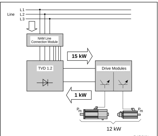
2.3. TVD 1.2 Power Supply Module
Modular power supply for more than one servo drive (typically 10)
Application Pm Pm
12 kW
EinbTVD12Ver Line L1 L2 L3 TVD 1.2 Drive Modules15 kW
NAM Line Connection Module1 kW
Fig. 2.7. TVD 1.2 service range.
Continuous mechanical power: 6 kW ③ TVD 1.2-08 12 kW ③ TVD 1.2-15
Line voltage: 3 x 380...460V AC (± 10%)
DC bus continuous power: 7.5 kW③ TVD 1.2-08 15 kW ③ TVD 1.2-15
Continuous regen power: 0.5 kW③ TVD 1.2-08 1.0 kW③ TVD 1.2-15 325 355 390 150 MBklTVD1Ver Dimensions
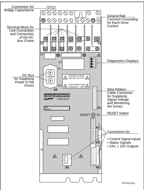
Front View Typ: Serien-Nr.: X1 POWER SUPPLY TM X2 X3 X4 P N X5 DANGER POWER 300 VDC OUTPUT DISCHARGE TIME Entladezeit > 1Min. FATVD12Ver X9 L+ L-S2 RESET X7 X7
Terminal Block for Line Connection and Connection of the DC Bus Choke DC Bus for Supplying Power to the Drives Ground Rail Common Grounding for Each Drive Control Wire-Ribbon Cable Connector for Supplying Signal Voltage and Monitoring the Drives RESET button Diagnostics Displays Connectors for: • Control Signal Inputs • Status Signals • 24V, ± 15V Outputs Connection for
Bridge Capacitance
• DOK-POWER*GENEREL****-AUS1-EN-E1,44 • 10.96
Functional Characteristics:
AC Power Input The TVD is available in two power levels. It can be used to supply power to main and servo drives having an overall continuous mechanical power output of either 6 kW or 12 kW.
The TVD can be connected directly to 380 ... 460 V, 50 ... 60 Hz three-phase power systems without the need for transformers. A power protection circuit is built in to isolate the drive equipment from the AC power system.
A soft-start circuit in the TVD prevents high inrush current spikes so that the line connection protection devices do not need to be oversized. Line connec-tions can be protected by circuit breakers or slow-blow fuses. Semiconductor-type circuit protection devices are not needed.
The TVD DC bus voltage is regulated so that variations in the line voltage have no effect on drive dynamics. In many cases this permits higher drive speeds to be achieved.
The TVD is always operated with a line filter. Thus, it causes virtually no line reaction. The NAM line conditioning module makes the TVD and the neces-sary filter components easy to install.
When the drives are running in generator mode, the regenerated energy is absorbed by a bleeder resistor. The TVD may be combined with the TBM 1.2 Auxiliary Bleeder Module to increase the continuous and peak regenerated power rating.
TCM 1 Auxiliary Capacitance Modules can be connected to the TVD. When the drives are being braked, the drive energy is stored in the DC bus so that it can be reused for acceleration. Heat losses in the enclosure and energy consumption are therefore minimal. Approximately 30 Ws can be stored per mF auxiliary capacitance.
A dynamic braking feature is provided on the TVD so that motors whose field is produced by a permanent magnet can even be braked if a fault occurs in the drive electronic system. If there is trouble in the drive electronic system or in the system installation (feedback line), the dynamic braking feature is acti-vated by the ready-state contact (Bb) on the TVD, causing the drives to brake to a stop.
The signal voltage is supplied to all drives via a wire-ribbon cable. In the event of a power failure, the electronic circuitry is supplied with power from the DC bus. The drives can therefore be stopped under velocity or position regulation when power failures occur. The line connections for supplying power to the drives and to electronic circuits are jumpered on the unit. Thus, an additional line connection for supplying power to the electronic circuits is not required.
The TVD is equipped with an extensive range of monitoring functions. It communicates with the drives by means of the wire-ribbon cable. Monitored parameters include: motor feedback, current and temperature of the drives, the load on the bleeder resistor, and line voltage. If trouble is encountered, the ready-state contact on the TVD causes the power supplied to the drives to be shut off immediately. LED displays provide for rapid trouble shooting. Direct Connection to Line Power Soft-start Regenerated Power Auxiliary Capacitance Modules Regulated DC Bus Line Reaction Dynamic braking
Supply of Power to the Electronic Circuits
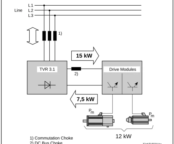
2.4. TVR 3.1 Power Supply Module
Modular power supply for multiple main and servo drives (typically 10)
Continuous mechanical power: 12 kW
Line voltage: 3 x 380...480 V AC ( ± 10 %)
DC bus continuous power: 15 kW
Continuous regen power: 7.5 kW
Application Dimensions
15 kW
7,5 kW
Pm EinbTVR31Ver Line L1 L2 L3 TVR 3.1 Drive Modules 1) Commutation Choke 2) DC Bus Choke 1) Pm12 kW
2) 325 355 390 150 MBklTVR3VerFig. 2.11. Dimensional drawing of TVR 3.1 power supply module. Fig. 2.10. TVR 3.1 service range.
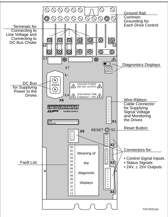
• DOK-POWER*GENEREL****-AUS1-EN-E1,44 • 10.96 Front View Typ: Serien-Nr.: X1 POWER SUPPLY TM X2 X3 X4 X5 DANGER POWER 300 VDC OUTPUT DISCHARGE TIME Entladezeit > 1Min. FATVR31Ver X9 L+ L-S2 RESET X7 X7 Terminals for Connecting to Line Voltage and Connecting to DC Bus Choke DC Bus for Supplying Power to the Drives Ground Rail Common Grounding for Each Drive Control
Wire-Ribbon Cable Connector for Supplying Signal Voltage and Monitoring the Drives Reset Button Diagnostics Displays Connectors for: • Control Signal Inputs • Status Signals • 24V, ± 15V Outputs Meaning of the diagnostic displays 00 01 02 03 04 05 06 07 08 09 10 11 12 13 Fault List
Functional Characteristics: AC Power Input Regulated DC Bus Line Reaction Regenerated Power Auxiliary Capacitance Modules Dynamic braking
Supply of Power to the Electronic Circuits
The TVR 3.1 can be used to supply power to main and servo drives having an overall continuous mechanical power output of up to 12 kW.
The TVR 3.1 can be connected directly to 380 ... 460 V, 50 ... 60 Hz three-phase power systems without the need for transformers. A power protection circuit is built in to isolate the drive equipment from the AC power system.
A soft-start circuit in the TVR 3.1 prevents high inrush current spikes so that the line connection protection devices do not need to be oversized. Line connections can be protected by circuit breakers or slow-blow fuses. Semi-conductor-type circuit protection devices are not needed.
The TVR DC bus voltage is regulated so that variations in the line voltage have no effect on drive dynamics. In many cases, this permits higher drive speeds to be achieved.
The TVR always operates with a line filter in use. Thus, it causes virtually no line reaction.
When the drives are running in generator mode, the energy from the drives is regenerated to the AC power system with low losses. In order to permit continued braking in the event of line trouble or outages, the TVR 3.1 is provided with a bleeder resistor as standard equipment. Thus a delayed power shutoff is not necessary in the event of an emergency stop.
Auxiliary Capacitance Modules can be connected to the TVR. These units store energy in the DC bus and can be used, for example, to perform a retraction move in the event of a power failure.
A dynamic braking feature is provided on the TVR so that motors whose field is produced by a permanent magnet can even be braked if a fault occurs in the drive electronic system. If there is trouble in the drive electronic system or in the system installation (feedback line), the dynamic braking feature is acti-vated by the ready-state contact (Bb) on the TVR, causing the drives to brake to a stop.
The signal voltage is supplied to all drives via a wire-ribbon cable.
In the event of a power failure, the electronic circuitry is supplied with power from the DC bus. The drives can therefore be stopped under velocity or position regulation when power failures occur.
The TVR is equipped with an extensive range of monitoring functions. It communicates with the drives by means of the wire-ribbon cable. Monitored parameters include: motor feedback, current and temperature of the drives, the load on the bleeder resistor, and line voltage.
If trouble is encountered, the ready-state contact (Bb) on the TVR causes the power supplied to the drives to be shut off immediately.
LED displays provide for rapid trouble shooting. Direct Connection
to Line Power
Soft-start
• DOK-POWER*GENEREL****-AUS1-EN-E1,44 • 10.96
2.5. KDV 2.3 Power Supply Module
Modular power supply for multiple main and servo drives (typically 10)
Application
30 kW
2 kW
Pm EinbKDV23Ver Line L1 L2 L3 KDV 2.3 Drive Modules 1) Autotransformer 2) DC Bus Choke 3) Auxiliary Capacitance Pm24 kW
2) 1) 3)Fig. 2.13. KDV 2.3 service range.
Continuous mechanical power: 24 kW
Line voltage: 3 x 220 V AC (+15% / -10%)
3 x 230 V AC (+10% / -15%)
DC bus continuous power: 30 kW
Continuous regen power: 2 kW
Dimensions 325 355 390 105 MBklTVD1Ver 160* Enclosure Wall * With Blower Cover 185
Heat-sink
Front View POWER SUPPLY AC SERVO SN240060-02029 A01 RESET S2 FAKDV2Ver DANGER POWER 300 VDC OUTPUT DISCHARGE TIME Entladezeit > 1 Min. AC POWER INPUT 3 x 220 V A C
DANGER HIGH VOL
TAGE Leistungseinspeisung ± 15% 50…60Hz X28 X28 a X12 X12 a X10 X10 a F3 F4 F2 X9 L+ X1 L-L3 L2 L1 Line Connection AC Power Input DC Bus For Supplying Power to the Drives Fuse +24V Fuse Control Voltage Line Connection Power to Blowers Ground Rail Common Grounding for Each Drive Control
Wire-Ribbon Cable Connector for Supplying Signal Voltage and Monitoring the Drives Reset Button Diagnostics Displays Connectors for: • Control Signal Inputs • Status Signals • 24V, ± 15V Outputs Connection for Heat Sink Blowers Power to Drive Control Blowers
X13 X14
Connection for DC Bus Choke
• DOK-POWER*GENEREL****-AUS1-EN-E1,44 • 10.96
Functional Characteristics:
AC Power Input The KDV 2.3 can be used to supply power to main and servo drives having an overall continuous mechanical power output of up to 24 kW. The actual effective output depends on the smoothing and commutation chokes, auxiliary capacitance modules and transformers used with the power supply. This permits the unit to be adapted to meet the needs of the given application. In many applications (AC power system with ground) the KDV 2.3 power supply can be adapted to the line voltage by using an autotransformer.
The KDV 2.3 achieves a high continuous output with low heat losses in the enclosure. The unit is designed to be installed with the heatsink extending through an opening in the back panel of the enclosure. Only about 20% of the total heat loss remains in the enclosure. The installation kit provided with the unit can be used to seal off the opening to achieve an IP 65 protection classification.
The costs of enclosing ventilation and cooling are significantly reduced when K-series power supplies are used.
Heat Losses in the Enclosure: Completely Enclosed Housing or Enclosure Heat Sink Heat Output Air Duct External Internal MZKDV2iSSV er Blower Motor Air Flow Heat Sink Blower PVint PVext Q = 45 l/s Pmax = 40 Pa VAir = 3...4 m/s
A soft-start circuit in the KDV 2.3 prevents high inrush current spikes so that the line connection protection devices do not need to be oversized. Line connections can be protected by circuit breakers or slow-blow fuses. Semi-conductor-type circuit protection devices are not needed.
When the drives are running in generator mode, the energy from the drives is absorbed by a bleeder resistor.
Auxiliary Capacitance Modules can be connected to the KDV 2.3 for applica-tions in which it must produce a maximum continuous output. With 14 ... 22 kW, a 2-mF auxiliary capacitance module is used. With 22 ... 30 kW, a 4-mF auxiliary capacitance module is used.
These units store energy from the DC bus and can be used, for example, to perform a retraction move in the event of a power failure.
A dynamic braking feature can be installed on the TVR so that motors whose field is produced by a permanent magnet can even be braked if a fault occurs in the drive electronic system. If there is trouble in the drive electronic system or in the system installation (feedback line), the dynamic braking feature is activated by the ready-state contact (Bb) on the KDV 2.3, causing the drives to brake to a stop.
The signal voltage is supplied to all drives via a wire-ribbon cable.
In the event of a power failure, the electronic circuitry is supplied with power from the DC bus. The drives can therefore be stopped under velocity or position regulation when power failures occur.
The KDV 2.3 is equipped with an extensive range of monitoring functions. It communicates with the drives by means of the wire-ribbon cable. Monitored parameters include: motor feedback, current and temperature of the drives, the load on the bleeder resistor, and line voltage.
If trouble is encountered, the ready-state contact (Bb) on the KDV 2.3 causes the power supplied to the drives to be shut off immediately.
LED displays provide for rapid trouble shooting. Soft-start Regenerated Power Auxiliary Capacitance Modules Monitoring Functions Dynamic braking
Supply of Power to the Electronic Circuits
• DOK-POWER*GENEREL****-AUS1-EN-E1,44 • 10.96
2.6. KDV 4.1 Power Supply Module
Modular power supply for multiple main and servo drives (typically 10)
Application
Continuous mechanical power: 24 kW
Line voltage: 3 x 380 ... 460 V AC (± 10%)
DC bus continuous power: 30 kW
Continuous regen power: 20 kW
Fig. 2.17. KDV 4.1 service range.
30 kW
2 kW
Pm EinbKDV41Ver Line L1 L2 L3 KDV 4.1 Drive Modules 1) Commutation Choke 2) DC Bus Choke 3) Auxiliary Capacitance Pm24 kW
2) 1) 3) DimensionsFig. 2.18. Dimensional drawing of KDV 4.1 power supply module. 325 355 390 150 MBklKDV4Ver 160* Enclosure Wall * With Blower Cover 185
Heat-sink
Front View X10 Typ: Serien-Nr.: X1 POWER SUPPLY TM FAKDV41Ver X13 X14 a b X9 a L+ L-RESET S2 X10 a F8 F7 F4 F3 X28a X28 X9 2L- 1L- 2L+ 1L+ L1 L2 L3 Line Connection AC Power Input DC Bus For Supplying Power to the Drives Fuse Control Voltage Connector for Control Voltages Ground Rail Common Grounding for Each Drive Control
Wire-Ribbon Cable Connector for Supplying Signal Voltage and Monitoring the Drives Reset Button Diagnostic Displays Connector for: • Status Signals • 24V, ± 15V Outputs Connection for Heat Sink Blowers Power to Drive Control Blowers Connection for DC bus Choke Fuse Blower Power
• DOK-POWER*GENEREL****-AUS1-EN-E1,44 • 10.96
Functional Characteristics:
AC Power Input
Heat Losses in the Enclosure: Direct Connection to Line Voltage
Soft-start
The KDV 4.1 can be used to supply power to main and servo drives having an overall continuous mechanical power output of up to 24 kW. The actual effective output depends on the smoothing and commutation chokes, auxiliary capacitance modules and transformers used with the power supply. This permits the unit to be adapted to meet the needs of the given application.
The unit can be connected directly to 380 ... 460 V, 50 ... 60 Hz three-phase power systems without using transformers.
The KDV 4.1 achieves a high continuous output with low heat losses in the enclosure. The unit is designed to be installed with the heatsink extending through an opening in the back panel of the enclosure. Only about 20% of the total heat loss remains in the enclosure. The installation set provided with the unit can be used to seal off the opening to achieve an IP 65 protection classification. The costs of enclosing ventilation and cooling are significantly reduced when K-series power supplies are used. (See Fig. 2.16.)
A soft-start circuit in the KDV 4.1 prevents high inrush current spikes so that the line connection protection devices to not need to be oversized. Line connections can be protected by circuit breakers or slow-blow fuses. Semi-conductor-type circuit protection devices are not needed.
The KDV 4.1 DC bus voltage is regulated so that variations in the line voltage have no effect on drive dynamics. In many cases, this permits higher drive speeds to be achieved.
When the drives are running in generator mode, the energy from the drives is regenerated to the AC power system with low losses.
In order to permit the braking in the event of line trouble or outages, the KDV 4.1 is provided with a bleeder resistor as standard equipment. Thus a delayed power shutoff is not necessary in the event of an emergency stop.
Auxiliary Capacitance Modules can be connected to the KDV 4.1 for applica-tions in which it must produce a maximum continuous output. With 14 ... 22 kW, a 2-mF auxiliary capacitance module is used. With 22 ... 30 kW, a 4-mF auxiliary capacitance module is used.
These units store energy in the DC bus and can be used, for example, to perform a retraction move in the event of a power failure.
A dynamic braking feature can be connected to the KDV so that motors whose field is produced by a permanent magnet can even be braked if a fault occurs in the drive electronic system. If there is trouble in the drive electronic system or in the system installation (feedback line), the dynamic braking feature is activated by the ready-state contact (Bb) on the KDV 4.1, causing the drives to brake to a stop. Regulated DC Bus Regenerated Power Auxiliary Capacitance Modules Dynamic braking
The signal voltage is supplied to all drives via a wire-ribbon cable. In the event of a power failure, the electronic circuitry is supplied with power from the DC bus. The drives can therefore be stopped in a controlled manner when power failures occur.
The KDV 4.1 is equipped with an extensive range of monitoring functions. It communicates with the drives by means of the wire-ribbon cable. Monitored parameters include: motor feedback, current and temperature of the drives, the load on the bleeder resistor, and line voltage.
If trouble is encountered, the ready-state contact on the KDV 4.1 causes the power supplied to the drives to be shut off immediately.
LED displays provide for rapid trouble shooting. Supply of Power to the
Electronic Circuits
• DOK-POWER*GENEREL****-AUS1-EN-E1,44 • 10.96
2.7. KVR 1.2 Power Supply Module
Modular power supply for multiple main and servo drives (typically 10)
Application
Fig. 2.20. KVR 1.2 service range.
Continuous mechanical power: 24 kW
Line voltage: 3 x 380 ... 460 V AC (± 10%)
DC bus continuous power: 30 kW
Continuous regen power: 15 kW
30 kW
15 kW
Pm EinbKVR12Ver Line L1 L2 L3 KVR 1.2 Drive Modules 1) Commutation Choke 2) DC Bus Choke 3) Auxiliary Capacitance 4) Bridge Capacitance 1) Pm24 kW
2) 3) 4) Dimensions 325 355 390 215 MBklKVR1Ver 160* Enclosure Wall * With Blower Cover 185Heat-sink
Front View X9 L+ L-POWER SUPPLY AC SERVO SN240060-02029 A01 X1 X2 X3 X4 X5 X7 LED +24V/±15V/+5V Meaning of Diagnostic Displays 00 01 02 03 04 05 06 07 08 09 10 11 12 13 RESET S2 1U1 1V1 1W1 1L+ 2L+ RB1 RB2 P N IB EB EPU-EPU+ 2U1 2V1 2W1 FAKVR12Ver Connection for DC Bus Choke Connection for Heat Sink Blowers DC Bus
For Supplying Power to the Drives Connection for Bridge Capacitance Line Connection AC Power Input List of Faults Line Connection
for Blower Power
Ground Rail Common Grounding for Each Drive Control Wire-Ribbon Cable Connector for Supplying Signal Voltage and Monitoring the Drives Reset Button Diagnostic Displays Connector for: • Control Signal Inputs • Status Signals • 24V; ±15V Outputs Power to Drive Control Blowers X13 X14b X14a
• DOK-POWER*GENEREL****-AUS1-EN-E1,44 • 10.96
Functional Characteristics:
AC Power Input
Heat Losses in the Enclosure: Direct Connection to Line Voltage
Soft-start
The KVR 1.2 can be used to supply power to main and servo drives having an overall continuous mechanical power output of up to 24 kW. The actual effective output depends on the smoothing and commutation chokes, auxiliary capacitance modules and transformers used with the power supply. This permits the unit to be adapted to meet the needs of the given application.
The KVR 1.2 can be connected directly to 380 ... 460 V, 50 ... 60 Hz three-phase power systems without using transformers. A power protection device to isolate the drive equipment from the AC power system is built in.
The KVR 1.2 achieves a high continuous output with low heat losses in the enclosure. The unit is designed to be installed with the heatsink extending through an opening in the back panel of the enclosure. Only about 20% of the total heat loss remains in the enclosure. The installation kit provided with the unit can be used to seal off the opening to achieve an IP 65 protection classification. The costs of enclosing ventilation and cooling are significantly reduced when K-series power supplies are used. (See Fig. 2.16.)
A soft-start circuit in the KVR 1.2 prevents high inrush current spikes so that the line connection protection devices to not need to be oversized. Line connections can be protected by circuit breakers or slow-blow fuses. Semi-conductor-type circuit protection devices are not needed.
The KVR DC bus voltage is regulated so that variations in the line voltage have no effect on drive dynamics. In many cases, this permits higher drive speeds to be achieved.
When used in combination with the chokes and capacitance modules supplied with the unit, the KVR operates without causing significant line reaction.
When the drives are running in generator mode, the energy from the drives is returned to the AC power system with low losses.
In order to permit the braking in the event of line trouble or outages, the KVR 1.2 is provided with a bleeder resistor as standard equipment. Thus, a delayed power shutoff is not necessary in the event of an emergency stop.
Auxiliary Capacitance Modules can be connected to the KVR 1.2 for applica-tions which require the maximum continuous DC bus output. With 25 ... 30 kW, a 2-mF auxiliary capacitance module is used
These units store energy in the DC bus and can be used, for example, to perform a retraction move in the event of a power failure.
An dynamic braking feature can be connected to the KVR so that motors whose field is produced by a permanent magnet can even be braked if a fault occurs in the drive electronic system. If there is trouble in the drive electronic system or in the system installation (feedback line), the dynamic braking feature is activated by the ready-state contact (Bb) on the KVR, causing the drives to brake to a stop.
Regenerated Power Line Reaction Regulated DC Bus Auxiliary Capacitance Modules Dynamic braking
The signal voltage is supplied to all drives via a wire-ribbon cable. In the event of a power failure, the electronic circuitry is supplied with power from the DC bus. The drives can therefore be stopped in a controlled manner when power failures occur.
The KVR 1.2 is equipped with an extensive range of monitoring functions. It communicates with the drives by means of the wire-ribbon cable. Monitored parameters include: motor feedback, current and temperature of the drives, the load on the bleeder resistor, and line voltage.
If trouble is encountered, the ready-state contact (Bb) on the KVR 1.2 causes the power supplied to the drives to be shut off immediately.
LED displays provide for rapid trouble shooting. Supply of Power to the
Electronic Circuits
• DOK-POWER*GENEREL****-AUS1-EN-E1,44 • 10.96
3.
Calculations and Selecting the Correct
Power Supply
The power supply for an AC drive system consists mainly of the power supply module. Additional transformers, chokes, auxiliary capacitance modules and bleeder modules may be used depending on the purpose for which the drives are being used, the design of the power supply module and the service conditions.
The power supply must provide the DC bus continuous power needed to operate the drives and the DC bus peak power needed for accelerations. When motors are operated in generator mode, the power supply must be able to handle the duration of power return and the peak return power. The power supply module also provides the signal voltages used to power the electronic circuitry on the drives.
The motors and drives which will be used must be identified before selecting the power supply module and accessory components.
It is recommended that the calculations described in 3.1 ... 3.8 be performed to ensure that the proper power supply configuration is used.
Mechanical Output
3.1. DC Bus Continuous Power
The DC bus continuous power is calculated based on the mechanical power taking into account motor and drive efficiencies and synchronization factors.
Pm = Mech. Power in W M = Torque in Nm
ω = Angular velocity in rad/s n = Speed in RPM
Pm = mech. Power in kW
The effective motor torque and the average motor speed are used to calculate the continuous mechanical power of a servo drive.
The effective motor torque can be taken over from the servo drive calcula-tion.
Mean motor speed:
For servo drive functions on conventional NC machine tools the average motor speed is about 20% of the rapid traverse speed. In certain cases it may be necessary to calculate the average motor speed exactly.
Calculate the average motor speed:
If the time during which the drive is operated at a constant RPM is significantly higher than the ramp-up or braking time:
or
P
M n
m=
⋅
9550
Continuous Mechanical Power for Servo Drives(3.1)
(3.2) Average Speed
Without Taking Ramp-Up and Braking Time into Account
nav = average motor speed in RPM n1...nn = motor speed in RPM t 1...tn = Cycle time in s
n
n t
n
t
n
t
t
t
t
av n n n=
⋅ + ⋅ + + ⋅
+ + +
1 1 2 2 1 2...
...
Formel3_3 n1 n2 n3 t1 t2 t3 t4 tP
m= ⋅ = ⋅
M
ω
M
2
π
n
60
• DOK-POWER*GENEREL****-AUS1-EN-E1,44 • 10.96
In dynamic applications with short cycle times, for example roller feeders and nibble machines, ramp-up and braking times are taken into account.
Average Speed Taking Ramp-Up and Braking Time Into Account
Formel3_4
n
t1 t2
t
tH tB
nav = average motor speed in RPM n = motor speed in RPM
t = time in s tH = ramp-up time tB = braking time
Mechanical Power for Servo Drives
PmS = mech. continuous power for servo drives in kW M
eff = effective motor torque in Nm nav = average motor torque in RPM
The mechanical power of the main drives can be calculated or determined from performance curves.
PmH = mechanical rated power for main drive (shaft output) in kW
Mn = torque in Nm n
n = rated motor speed in RPM
(3.4)
(3.5)
P
mH=
M n
n⋅
n9550
Mechanical Power for Main Drives
P
mS=
M
eff⋅
n
av9550
n
n
t
n t
n
t
t
t
t
t
av H B H B=
⋅ + ⋅ + ⋅
+ + +
2
12
1 2 (3.3)DC Bus Continuous Power for Servo Drives Simultaneity Factors (3.6) DC Bus (3.7) DC Bus Continuous Power for Main and Servo Drives
For Machine Tools
(3.8)
P
P
P
P
K
F
DCS mS mS mSn G=
(
1+
2+ +
...
)
⋅
1
The power supply module must supply the DC bus power for all servo drives. However only in a very small number of applications are all the drives equally loaded. Thus, only the simultaneous power requirements need to be taken into account.
In actual practice the following simultaneity factors have been found to be an accurate reflection of conditions encountered in typical NC feed axes.
Number of Axes 1 2 3 4 5 6
Simultaneity Factor 1 1.15 1.32 1.75 2.0 2.25
The selection of transformers, chokes and auxiliary capacitance modules is based on the actual required DC bus continuous power. It is determined by the rated power of the main drives. When selecting the power supply modules be certain that their maximum DC bus continuous power is not limited by the short-term operating power of the main drives.
If more than one main drive is to be operated on an DC bus, add together the simultaneously required powers.
Add together the simultaneously required powers.
On typical NC machine tools the main drive primarily determines the required DC bus power.
0.3 = Empirical value for standard machine tools F
G = Simultaneity factor
K1 = Constant for motor and drive efficiency and current waveform factor
K1 = 1.25 with TVD 1.2, TVR 3, KDV 2.3, KDV 4.1 (with DC bus choke)
K1 = 1.8 with TVM
(without DC bus choke) PDC = DC bus continuous power in kW
PDCH = DC bus continuous power for main drives in kW PDCS = DC bus continuous power for servo drives in kW P
mS1 = Continuous mechanical power of servo drive 1 in kW PmH = Rated power for main drive (shaft output) in kW
P
DCH=
P
mH⋅
K
1
P
DC=
[
P
mH+
0 3
.
(
P
mS1+
P
mS2+ +
...
P
mSn)
]
⋅
K
1
Meaning of symbols: See 3.8.• DOK-POWER*GENEREL****-AUS1-EN-E1,44 • 10.96
3.2. DC Bus Peak Power
The total of the peak outputs of all drives which accelerate simultaneously must not be greater than the peak output of the power supply module. The DC bus peak power is required of the power supply module when, for example, a number of axis accelerate simultaneously to their rapid-traverse speeds and traverse to the workpiece.
K1 = Constant for motor and drive efficiency and current waveform factor
K1 = 1.2 with power supplies with DC bus choke K1 = 1.2 with power supplies
without DC bus choke
MNC = Acceleration torque in NC operation in Nm MG = Weight torque with vertical axes in Nm neil = RPM in rapid traverse
Ppeak = DC bus peak power in kW
PKB-03= DC bus peak power of the power supply module in kW
3.3. Regenerated Energy
The energy content of all main and servo drives which in the worst case brake at the same time must not exceed the maximum regenerated energy of the power supply module per data sheet. If this is not taken into account in the design of the system, the bleeder resistor in the power supply may be overloaded.
Wrot = Rotational energy in Ws
Wmax = Max. permissible regenerated energy of the power supply module in kWs
n
eil = RPM in rapid traverse
Jg = Inertial torque (motor + load) in kgm2
DC Bus Peak Power
per Drive (3.9)
Regen Energy per Drive
Total Regen Energies
(3.11)
(3.12) Total of DC Bus Peak
Powers
∑
P
peak≤
P
KB−03 (3.10)W
rot=
J
g
n x
eil
2
2
60
2π
W
rot≤
W
∑
maxP
peak=
(
M
NC±
M
G)
⋅
n
eil⋅
K
1
9550
In servo drive applications in which a high number of acceleration and deceleration operations are common, for example in nibble machines and roll feed units, auxiliary capacitance modules can be connected to the DC bus. This prevents the bleeder resistor from being activated in the power supply module when the drives are braked, which significantly reduces the heat losses generated in the enclosure. The stored energy can be used for acceleration, reducing the energy consumed by the system.
WZW = Energy which can be stored in the DC bus CZW = DC bus capacitance in F
UB = Bleeder response threshold ca. 425 V UN = Rated voltage
— 320 V with TVD, TVR, KVR and KDV 4 — 345 V with TVM and KDV 2
(300 V + 15% overvoltage)
The auxiliary capacitance modules must be designed so that they can store the rotational drive energy.
CZu = Auxiliary capacitance in mF W
rot = rotational energy in Ws
Approximately 40 Ws can be stored per mF auxiliary capacitance on power supply modules equipped with a regulated DC bus voltage (TVD, TVR, KVR, KDV 4)
It is recommended that with power supply modules which are not equipped with a regulated DC bus (TVM, KDV 2) the auxiliary capacitances be designed for 15% overvoltage. If this is done, approx. 30 Ws can be stored per mF auxiliary capacitance.
Auxiliary Capacitance for Energy Storage
(3.13) (3.14)
W
ZWC
ZWU
U
B N=
(
)
2
2 2–
C
W
U
U
mF
Zu rot B N≥
(
2
2 2)
⋅
1000
2
–
–
• DOK-POWER*GENEREL****-AUS1-EN-E1,44 • 10.96
3.4. Continuous Regenerated Power
The total of the continuous regenerated power from all drives averaged over time must not exceed the continuous regenerated power.
With servo drive applications on typical NC machine tools, the machining time is relatively large compared to the total cycle time. The continuous regener-ated power is low. In general, it cannot be calculregener-ated exactly. It is sufficient, however, if the peak regenerated power calculated per section 3.5 is not exceeded.
An exact calculation is necessary in certain circumstances. Such circum-stances can be:
• Servo drive applications having a high number of acceleration and braking operations, for example on nibble machines and roll feeds.
• Machine tools having a modular main drive
• Applications in which relatively large masses must be lowered, for example on load crane and in storage and material handling technology
To calculate the continuous regenerated power, the rotational energy of the drives and the potential energy on nonbalanced masses must be known.
W
rot = Rotational energy in Ws neil = RPM during rapid traverse
Jg = Inertial torque (motor + load) in kgm2 z = Number of braking operations per cycle
m = Load mass in kg
g = Descent acceleration in 9.81m/s2 h = Descent height in m
Wpot = Potential energy in Ws
z = Number of lowering operations per cycle
PRD =Continuous regenerated power in kW tz = Cycle time in s
Wpotg = Total of potential energies in kWs Wrotg = Total of rotational energies in kWs
Rotational Energy (3.15) Continuous Regenerated Power (3.17) (3.16) Potential Energy
P
W
W
t
RD rotg potg z=
+
W
pot= ⋅ ⋅ ⋅
m g h z
W
rot=
J
g
n
eil⋅
⋅
z
2
2
60
2π
(3.18) (3.19) Individual Lowering Operation Within a Cycle
W
t
F v
P
pot ab RD= ⋅ ≤
W
s
F v
t
s
P
pot ab RD10
= ⋅ ⋅
10
≤
(3.20)P
RS≤
P
BM∑
If a load is lowered over a time greater than 10 s, the regenerated power cannot be greater than the maximum continuous regenerated power of the power supply module.
If the lowering operations are less than 10 s, the regenerated power can be greater, however, the continuous regenerated power of the power supply module cannot be exceeded in average time periods of 10 s.
F = Weight force in N v = Velocity in m/s
tab = Duration of lowering in s
PRD = Continuous regenerated power in W Wpot = Potential energy in Ws
3.5. Peak Regenerated Power
Peak regenerated power is usually encountered if an emergency stop is triggered and all axes brake simultaneously.
The total of the peak regenerated power from all servos which potentially can brake simultaneously must not exceed the power supply module's peak bleeder power. If this requirement is not taken into account in designing the drive, the DC bus voltage can increase to too high a level upon emergency stop and damage the drive equipment.
The peak regenerated power of the servo drives may be found in the motor selection documents.
As a rule of thumb, the peak regenerated power can be calculated as follows:
Mmax = Max. drive torque in Nm nmax = Max. NC useful speed in RPM PRS = Peak regenerated power in kW PBM = Peak bleeder power in kW
(3.21)
P
RS=
M
⋅
n
⋅
max max,
9550 1 25
• DOK-POWER*GENEREL****-AUS1-EN-E1,44 • 10.96
3.6. Power Requirements
The power requirements are calculated so that transformers, commutation chokes, AC power protection and conductor cross sections can be properly specified.
The power requirements depend on the continuous power of the drives and on the operating principle used by the power supply module.
Power requirements for power supply modules having a connection voltage of 3 x 220 V (TVM 2, KDV 2).
or without DC bus choke
with DC bus choke
The line transformer power must be at least twice as large as the calculated connection power.
SAn = Connection power in kVA PDC = DC bus continuous power in kW Pm = Continuous mechanical power in kW UN = Line voltage in V I N = Line current in A Power for TVM 2 and KDV 2 (3.22) (3.23) (3.24)
S
An=
P
DC⋅
1 05
.
S
AN=
P
m⋅1 89
.
S
An=
P
m⋅
1 31
.
I
S
U
N An N=
⋅
⋅
1000
3
S
AN=
P
DC⋅
3
⋅
U
N25 5
.
S
P
U
V
An DC N=
⋅
2
⋅
320
(3.25) (3.26) (3.27) Power for TVD, TVR and KVRAC Current from the Mains Power System Power for KDV 4
3.7. Power Requirements for Motor and Heat Sink
Blowers
The blowers on the servo drive motors and the heat sink blowers for equipment from the „K series“ are available for connection to 230 V AC and 115 V AC. If line voltages differ from these voltages, an auto- transformer can be used for adaptation purposes. The connection of the individual blowers is stated in the following table.
Loading Capacity of
Control Voltages Power Supply Module
Power to Electronic Circuits
Line Connection Capacity
Connection Power Connection Voltage +24V +15V -15V 115/230V or 230/400V 3 x 380-460V AC 3 x 380-480V AC 230 V 230 V 3 x 380-460V AC 550 VA 300 VA 500 VA 500 VA 500 VA 500 VA 8A 7,5A 11A 12A 11,5A 11A 1,3A 2,5A 2A 2A 2A 2A 1A 1,5A 2A 2A 2A 2A TVM 2.4-50-220/300-W1 TVD 1.2-..-3 TVR 3.1-W15-3 KDV2.3-100-220/300-000 KDV 4.1-30-3 KVR 1.2-30-3
Fig. 3.2. Loading capacity of the control voltages.
Equipment Blower
Heat sink blower for KDV, KVR, KDS and KDA
MAC 63 motor blower MAC 71 motor blower MAC 90, MAC 93, MAV 112,
MAC 115 motor blowers MAC 132 motor blower Axial blower for MDD 65 and MDD 71 Axial blower for MDD 90, MDD 112 and
MDD 115 Connection Power 70 VA 22 VA 31 VA 55 VA 80 VA 30 VA 58 VA Fig. 3.1. Connection power for motor and heat sink blowers.
3.8. Power for the Electronic Circuits
The +24 V, ± 15 V control voltage outputs must not be overloaded by the processing of drive control signals. If the control voltages are used outside the drive system, for example to supply voltage to auxiliary relays, this must be taken into account.
• DOK-POWER*GENEREL****-AUS1-EN-E1,44 • 10.96
Power Consumption
for Processing Signals Equipment Designation 24VL
in mA +15VM in mA -15VM in mA TDM 1..-30-300-W0 TDM 1..-30-300-W1-000 TDM 1..-50-300-W1-000 TDM 1..-100-300-W1-000
Servo Drives TDM 1.2 and TDM 1.3
250 350 350 400 140 60 TDM 3..-20-300-W0 TDM 3..-30-300-W1 TDM 4..-20-300-W0 TDM 4..-30-300-W1
Servo Drives TDM 3.2, TDM 3.3, TDM 4.1 and TDM 4.3
400 800 400 800 120 125 150 50 55 60 KDS 1.1-030-300-W0 KDS 1.1-050-300-W1 KDS 1.1-100-300-W1 KDS 1.1-150-300-W1 MAC tachometer feedback
Servo Drives KDS 1.1 750 950 1450 1950 -140 24 50 3 DDS 2.1-...-DA01-00 DDS 2.1-...-DA02-00 DDS 2.1-...-DA03-00 DDS 2.1-...-DS01-00 DDS 2.1-...-DS03-00 DDS 2.1-...-DS04-00 DDS 2.1-...-DS05-00 DDS 2.1-...-RA01-00 DDS 2.1-...-RA02-00 DDS 2.1-...-RS01-00 DDS 2.1-...-RS03-00 DDS 2.1-...-RS04-00 Servo Drives DDS 2.1 670 700 710 710 890 840 1040 570 570 610 760 740 180 150 190 150 200 150 170 190 180 150 190 150 180 150 150 190 KDA 3.2-050-300-...-W1 KDA 3.2-100-300-...-W1 KDA 3.2-150-300-...-W1 TDA 1.1-050-3-... TDA 1.1-100-3-...
Main Spindle Drives KDA 3.2 and TDA 1.1
1200 1400 1600 1200 1400 160 160
4.
Index
A
AC Drive System 5
AC power system protection 38 Acceleration 34
Applications area 6
Auxiliary bleeder module 11, 14
Auxiliary capacitance module 14, 21, 24 Auxiliary capacitances 11, 14, 17, 21, 24, 28 auxiliary capacitances 33
Average motor speed 31
B
Bleeder peak power 37 Bleeder resistor 5, 17, 35
C
Calculations 30 Capacitances 35 Chokes 33 Commutation chokes 38 Conductor cross sections 38 Connection power 38Connection voltage 11 Control voltages 39
D
DC Bus Continuous Power 31, 33 DC Bus Peak Power 34
DC bus voltage 5
Dimensions 9, 12, 15, 18, 22, 26
Direct connection to AC power 14, 17, 24, 28 Drives 5
Dynamic braking 11, 14, 17, 21, 24, 28
E
Effective motor torque 31
Electronic circuits, power to 11, 14, 17, 21, 25, 29, 39 Energy content 34 Energy requirements 35 Energy Storage 35
F
Fault correction 17, 29 Fault diagnostics 11, 14, 21, 25 Front View 10, 13, 16, 19, 23, 27 Functional Characteristics 8 Fuses 11H
Heat loss in enclosure 20, 24, 28
I
Inrush current, peak 14, 17, 24, 28 Installation 20, 24, 28
• DOK-POWER*GENEREL****-AUS1-EN-E1,44 • 10.96
K
KDV 2.3 18 KDV 4.1 22 KVR 1.2 26L
Line conditioning module NAM 14 Line connection 24
Line current 38 Line voltage 11 Line voltage failure 14
M
Machine Tools 33 Mechanical output 32
Monitors 11, 14, 17, 25, 29 Motor and Heat Sink Blowers 39 Motors 5
P
Performance Characteristics 6 Potential Energy 36 Power Consumption 40 Power failure 17, 21, 29 Power protection 14, 17, 28 Power range 6 Power rectifier 5Power Supply Module 5
Power system reaction 14, 17, 28
R
Ready-state contact 11
Regenerated energy 5, 11, 14, 21, 34 Regenerated power 11, 14, 17, 24, 28 Regenerated power, continuous 36 Regenerated power, peak 37 Regulated DC Bus 14, 17, 24, 28 Rotational drive energy 35
Rotational energy 36
S
Selection Data 7 Signal voltage bus 5 Simultaneity Factors 33 Soft-start 14, 17, 21, 24, 28
Supply of power 5, 11, 14, 17, 20, 24, 28, 38 Supply of signal voltage 5
T
Transformers 33, 38 TVD 1.2 12
TVM 2.4 9
5.
Additional Documentation
Selection
Dimensioning
Design, Assembly, Installation, Startup,
Operation, Diagnostics, Service
KDV4 KDV2.3 KDV 2.3 Power Module for AC Drives Description of Application Doc. No.: 209-0049-4303 KVR 1.2 Power Supply Modules for AC Drives KDV 4
Power Supply Module for Direct Connection to AC Power System at 3xAC (380-460)V
Description of Application Doc. No.: 9.566.002.4
Power Supply Modules for AC Drives
Selection and Dimensioning Manual
Doc. No.: 209-0049-4301
KVR 1.2
Power Supply Module for Direct Connection to AC Power System at 3xAC (380-460)V Description of Application Doc. No.: 9.580.002.4 TVD 1.2 TVR 3.1 TVM 2.4 TVM 2.4 Power Module for AC Drives Description of Application Doc. No.: 209-0049-4302 TVD 1.2
Power Supply Module for Direct Connection to AC Power System at 3xAC (380-460)V
Description of Application Doc. No.: 9.573.001.4
TVR 3.1
Power Supply Module for Direct Connection to AC Power System at 3xAC (380-480)V
Description of Application Doc. No.: 209-0049-4304
Design, Assembly, Installation, Startup,
Operation, Diagnostics, Service
Selection
Dimensioning