Specifying Artifact-Centric Business Process
Models in UML: Technical Report
Montserrat Estañol1, Anna Queralt2, Maria-Ribera Sancho1,2, and Ernest Teniente1
1
Universitat Politècnica de Catalunya, Barcelona, Spain estanyol|ribera|teniente@essi.upc.edu, 2
Barcelona Supercomputing Center, Barcelona, Spain anna.queralt@bsc.es
Abstract. In recent years, the artifact-centric approach to process mod-eling has attracted a lot of attention. One of the research lines in this area is finding a suitable way to represent the dimensions in this approach. Bearing this in mind, this paper proposes a way to specify artifact-centric business process models by means of well-known UML diagrams, from a high-level of abstraction and with a technology-independent perspective. UML is a graphical language, widely used and with a precise semantics.
Key words: Business Artifacts, BALSA Framework, UML, Business Process Modeling
1 Introduction
Business process modeling (BPM) is one of the most critical tasks in the busi-ness’s definition, as business processes are directly involved in the achievement of an organization’s goals, and thus they are key to its success. When modeling business processes, it is important that the final models are understandable by the people involved in them. Moreover, they should be formal and precise enough in order to be able to automatically check their correctness at definition time, thus preventing the occurrence of errors when the business is deployed.
Traditionally, business processes have been modeled following a process-centric approach, which focuses on the activities or tasks in the process, un-dermining the data needed to carry them out. In contrast, in the artifact-centric approach the data required by the processes plays a key role in their definition. In particular, business artifacts model key business-relevant entities which are updated by a set of services that implement the business process tasks.
In addition tobusiness artifacts, an artifact-centric approach to process mod-eling should include a way to specify thelifecycle of the artifacts, i.e. the rele-vant stages in their evolution; theirassociations, i.e. the conditions under which changes are made to the artifacts and the services that are in charge of evolv-ing them. By usevolv-ing different models and constructs in each of these dimensions, one can obtain different process models with diverse characteristics. One of the
2 Montserrat Estañol et al.
research lines in this area is focused on finding a suitable way of representing these dimensions.
The artifact-centric approach has great intuitive appeal to business man-agers and developers [1] and it has been successfully applied in practice [2]. An additional advantage of this approach over the process-centric one is that the presence of data in the models facilitates performing automated reasoning on them. That is, it is possible to define formally what each task does and to assess whether the models are correct considering the meaning of the tasks and the requirements of the business.
Following these ideas, we propose to specify artifact-centric business process models by means of well-known UML diagrams, from a high-level of abstraction and with a technology-independent perspective. UML is a graphical language, widely used and with a precise semantics. Therefore, it may be understandable by people involved in the business process, both from the business and from the system development perspectives. UML provides also extensibility mechanisms that permit more flexibility without losing its formality. These characteristics are important requirements in artifact-centric process modeling [3].
Generally, UML diagrams make use of some textual notation to precisely specify those aspects that cannot be graphically represented. We will use the OCL (Object Constraint Language) for that purpose.
The choice of using UML diagrams does not necessarily restrict our approach to this language since alternative diagrams or languages could be used for model-ing some of the dimensions, provided that they allow specifymodel-ing all the features required on it. We have chosen UML for the advantages just mentioned and because it intuitively maps to the dimensions.
Currently, several alternatives have been proposed to model artifact-centric business processes, such as Guard-Stage-Milestone (GSM) models [4, 5, 6], BPMN with data [7] or PHILharmonic Flows [8], to mention a few examples. However, as we will see, these approaches either do not use the same language to represent all the dimensions or the chosen representation is not graphical - it is often based on some variant of logic - making the models difficult to understand. The use of natural language in some of the proposals may lead to ambiguities and errors.
Our approach allows also automated reasoning from the business process models (as shown on [9, 10]), while most of the existing proposals that han-dle reasoning are based on models which use languages grounded on complex mathematical notations [11, 12, 13] which are not practical at the business level. The work we present in this paper extends our work in [14, 15] by presenting a detailed methodology to model business processes from an artifact-centric per-spective. We illustrate this methodology by means of a complex example, taken from [16], which requires handling multiple business artifacts interacting together (and not only single-artifact systems as considered in our previous work). We also outline the different alternative diagrams that might be used for modeling each dimension and provide a more detailed comparison with related work.
2 Our Approach to Artifact-centric Process Modeling
The artifact-centric approach to business process modeling provides four explicit, inter-related but separable, dimensions in the specification of the business pro-cess, as described in the BALSA framework [1]: Business Artifacts, Lifecycles, Associations and Services. We summarize here the most relevant characteristics of each dimension:
– Business artifacts represent the data required by the business and whose evolution we wish to track. Each artifact has an identifier and may be related to other artifacts, as represented by the associations among them.
– Thelifecycleof a business artifact states the relevant stages in the evolution of the artifact, from the moment it is created until it is destroyed. Each business artifact is going to have a lifecycle.
– Associationsestablish the conditions under which the activities of the busi-ness process should be executed. That is, they determine the execution order of the services to allow the artifact to perform a transition from one stage of its lifecycle to another.
– Services, or tasks, represent atomic units of work and they are in charge of creating, updating and deleting the business artifacts. They correspond to the atomic acitivites of the associations, i.e. those which are not further decomposed.
Apart from business artifacts, businesses may also need to store data that does not really evolve. We will refer to this data asobjects.
The modeling approach we propose here is based on representing the BALSA dimensions using UML and OCL: UML class diagrams for business artifacts; UML state machine diagrams for lifecycles; UML activity diagrams for associa-tions, and OCL operation contracts for services. However, this choice does not restrict our approach to this subset of diagrams since, as we shall see, other alternatives may be used provided that they follow the methodology described. We call our approachBAUML(BALSA UML, for short).
Figure 1 shows the dimensions in the BALSA framework and their represen-tation in the BAUML approach. Roughly, our methodology behaves as follows. Business artifacts correspond to some of the classes in the class diagram. For each artifact, a state machine diagram is defined stating its lifecycle. Then, each transition of the state machine diagram is further specified by means of an ac-tivity diagram determining the associations of the artifact. Finally, the behavior of the atomic activities from each activity diagram is precisely defined through an operation contract.
The remainder of this section presents in more detail our methodology for artifact-centric business process modeling using the BAUML approach. We also describe the components of the different diagrams and how they relate to the other diagrams.
4 Montserrat Estañol et al.
Class Diagram (Artifacts)
State Mach. Diag. (Lifecycles)
Operation Contracts (Services)
Activity Diagram (Associations)
Fig. 1. Representation of the BALSA dimensions in our approach, adapted from [1] .
2.1 Business Artifacts as a Class Diagram
The class diagram will have a set of classes and associations representing the data and their relationships as required by the business process. Some of the classes, those with an important dynamic behavior, will represent business artifacts. An artifact must necessarily be the top class of a hierarchy whose leaves are dynamic subclasses so that the artifact can change its type from one subclass to another. Each subclass represents one of the specific states in the evolution of the artifact. They must fulfill the disjointness constraint (since an artifact cannot be in two states at the same time), but they can fulfill the completeness constraint (i.e. the artifact must have any of its subtypes) or not. If the artifact has a multi-level hierarchy, these rules apply to all the levels.
The advantage of using a hierarchy of subclasses to represent the potential states of an artifact is that it is possible to represent the attributes and relation-ships that are needed in each of the possible states while keeping the artifact’s original identifier and the relationships that are common to all states (or several substates).
UML class diagrams can represent, in a graphical way, the classes with their corresponding attributes, the relationships between those classes, and integrity constraints. Artifacts will have stereotype «artifact» in their corresponding class. We will refer to the classes that do not correspond to business artifacts as objects.
Integrity constraints correspond to restrictions over the classes, the at-tributes, or the relationships between them. Those integrity constraints that cannot be represented graphically in the class diagram should be described in OCL to ensure their formality. However, they could also be specified using nat-ural language for easier readability.
Alternative representations to the class diagram could be an ER or an ORM diagram. Both diagrams also allow defining the artifacts, the objects and their relationships in a graphical way.
2.2 Lifecycles as State Machine Diagrams
Each artifact in the class diagram will have a state machine diagram. This state machine diagram will have a set of states, a set of events, a set of effects and a set of transitions between pairs of states.
The states in the state machine diagram will correspond to the subclasses of the artifact if the hierarchy is complete. If it is incomplete, then the state machine diagram will have another state for the superclass. In this context, this state will represent an artifact that does not have any of the subtypes of the superclass. These rules apply to any multi-level hierarchy in the artifact.
The state machine diagram will also show the allowed transitions between states. Finally, we also define the initial states as a subset of the states which act as a target state for the initial transitions. Those initial transitions will always result in the creation of a new artifact instance.
Each transition will have a source state and a target state. Moreover, it may also have an OCL condition over the class diagram, an event and a tag representing the result from the execution of the event. We differentiate between three types of transitions (the elements inside parenthesis are optional): – ([OCL]) ExternalEvent ([tag])
– ([OCL]) TimeEvent (/ Effect) – [OCL] (/ Effect)
The first transition type will take place when ExternalEvent takes place and the OCL condition is true. If there is atag, then the result of the execution of ExternalEvent must coincide withtagfor the transition to take place. The second transition will take place when there is aTimeEventand the OCL condi-tion is true. If there is anEffect, the changes specified by it will also be made. Finally, the last transition type is similar to the second excepting the occurrence of a time event. These transition types cover the types of transitions allowed in the UML 2.4.1 specification that are significant at the specification level, as explained in [17].
AnExternalEventwill have as input parameters the artifacts in whose tran-sitions it appears or the identifiers of those artifacts. The execution of these events and their respectivetags (if any) will be defined in an activity diagram. Effects correspond to atomic tasks that have as input parameters the artifacts involved in the transition.
OCL is an OCL expression which starts from self or
Class.allInstances()->... where Class is any of the classes in the class diagram. A TimeEvent represents an occurrence of time. We distin-guish between relative and absolute time expressions. An absolute expression has the form at(time_expression); a relative expression has the form after(time_expression).
Notice that this state machine diagram does not follow exactly the UML standard described in [18]. This is due to the fact that it has tags, which we use to determine whether the event ends successfully or not. In traditional UML state machine diagrams, events are atomic and there is no need for such conditions.
6 Montserrat Estañol et al.
In addition, we also allow more than one outgoing transition from the initial node. This is useful when the artifact can be created in different ways. Alter-natively, this situation could be represented using one outgoing transition from the initial node, leading to a state calledInitialState. From this state, we could have the outgoing transitions that start from the initial node and leave the rest of the state machine diagram as it is. However, representing the lifecycles in this way does not contribute any relevant information and adds complexity to the final diagram.
Although we use a variant of UML state machines, any other notation based on state machines would be useful to represent the lifecycles of the artifacts.
2.3 Associations as Activity Diagrams
For every ExternalEvent in a state machine diagram, there will exist exactly one activity diagram. An activity diagram will have a set of nodes and a set of transitions between those nodes. More specifically, the activity diagram will have exactly one initial node and one or several final nodes. Transitions will determine the change from one node to the next. Apart from a source node and a target node, transitions may also have a guard condition and a tag. The tag will determine the correct or incorrect execution of the activity diagram, and will connect it to the right transition in the state machine diagram.
We distinguish between the following node types: – Initial Node:Point where the activity diagram begins
– Final Node:Point where the flow of the activity diagram ends.
– Gateway Node:Gateway nodes are used to control the execution flow. We distinguish betweendecision nodes,merge nodes,inclusive-or nodes,fork nodes
andjoin nodes.
– Activity: An activity represents work that is carried out. We differentiate three types of activities. A task corresponds to a unit of work with an asso-ciated operation contract. The operation contract will have a precondition, stating the conditions that must be true for the task to execute, and a post-condition, indicating the state of the system after the task’s execution. Both are formalized using OCL queries over the class diagram.Material actions cor-respond to physical work which is carried out in the process but that does not alter the system. Finally, a subprocess represents a “call” to another activity diagram, and as such may include several tasks and material actions.
We assume the following: decision nodes and fork nodes have one incoming flow and more than one outgoing flow; merge nodes and join nodes have several incoming flows and exactly one outgoing flow; activities have one incoming flow and one outgoing flow; initial flows have no incoming and one outgoing flow; and final nodes may have several incoming flows but no outgoing flow.
Guard conditions are only allowed over transitions which have a decision or an inclusive-or node as their source. The guard condition may refer to either: – The result of the previous task
– An OCL condition over the class diagram – A user-made decision
On the other hand, tags are only allowed over those transitions that have as target a final node.
During the execution of the activity diagram we assume that the constraints established by the class diagram may be violated. However, at the end of the execution they must be fulfilled, otherwise the transition does not take place and the changes are rolled back.
Finally, activity diagrams may also represent the main artifact involved in each of the tasks and its participants (i.e. the role of the person who carries out a particular activity) using swimlanes and notes, respectively as described in [14, 15]. However, for easier readability of the diagrams we do not show them in this paper.
Although we adopt the UML activity diagrams to represent the associations, they could also be represented using other notations (as long as they follow the semantics) such as BPMN or DFDs. BPMN is probably the language that is most used to represent business process models, and as such it offers a great variety of syntactic sugar for the basic node types described above. Data-Flow diagrams (DFD) are also another alternative, as they show the task and the inputs and outputs of data required and generated by them.
2.4 Tasks (Services) as Operation Contracts
As we have mentioned, each of the tasks in the activity diagrams will have an associated operation contract. The same applies to effects in the state machine diagrams. The contract will have a set of input parameters, a precondition, a postcondition and may have an output parameter. The input and output pa-rameters may be classes or simple types (e.g. strings, integers). If several tasks belong to the same activity diagram and their input parameters have the same names, we assume that their value does not change from one task to the next.
The task can only be executed when the precondition is met, and the post-condition specifies the state of the system after the execution of the operation. We also assume a strict interpretation of operation contracts to avoid redundan-cies [19]. Those classes that do not appear in the postcondition keep their state from before its execution.
We choose OCL to represent the operation contracts because it is a formal language that avoids ambiguities, it integrates naturally with UML and is in-dependent from the final implementation of the process. For easier readability, they could be specified in natural language, although we do not recommend it because it is prone to ambiguities and errors.
3 Running Example
Our running example is based on the backend process of a CD online shop, extracted from [16] and remodeled following our approach. The shop splits
cus-8 Montserrat Estañol et al.
tomer requests into different orders to the CD suppliers. The difficulty in this example lies in the representation of the relationship and the interaction between two different business artifacts: the quote requests made by the customers and the orders into which a quote request may be split (which in turn may involve several quote requests).
In particular, this shop keeps no stock of items, rather, the store obtains the CDs from its supplier after a customer request. The customer places a quote request for one or more CDs. Then the CD shop calculates the price of the order and informs the customer. If the customer accepts the quoted price, then the shop orders the CD to its suppliers, grouping in a single order to a supplier several quote requests. When the company receives the orders from the suppliers, they are then regrouped into the orders for the customers. The CD shop keeps track of the evolution of the quote requests from the customers and the orders the company makes to its suppliers.
3.1 Class Diagram
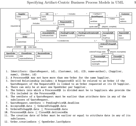
Figure 2 shows the class diagram for our example. There are two business ar-tifacts: QuoteRequestand Order, as shown by the stereotypes. The rest of the classes in the diagram, such as Supplier, Customer or CD represent objects: relevant information for the business but whose evolution we do not track. Each artifact has its own identifier, in this case, for bothQuoteRequestandOrderthe identifier isid. The rest of classes in the diagram may also have their identifiers, for instance, aCD is identified by both its nameand author. Each artifact and object has as many attributes and relationships as relevant for the business1.
Artifact Order is the simpler of the two. It has three different subclasses: OpenOrder, ClosedOrder and ReceivedOrder which contain the relevant in-formation for that particular state of the artifact. An OpenOrderis waiting to be sent to the supplier and additionalQuoteRequests can be assigned to it. A ClosedOrder has already been sent to the supplier. Finally, an Order changes its state toReceivedOrderwhen it has been received at the shop.
On the other hand, artifact QuoteRequest has a first level of sub-classes which are PendingPriceQR,PendingConfirmationQR, AcceptedQR and RejectedQR. A PendingPriceQR is waiting for the shop to quote the price. A PendingConfirmationQRhas already a price and is waiting for the customer’s acceptance or rejection. An AcceptedQR has already been accepted by the cus-tomer. In contrast,RejectedQR has been rejected.
AcceptedQR has one subclass:OrderedToSuppQR. Notice that the hierarchy is incomplete. An OrderedToSuppQRhas already been split into severalOrders that will eventually be processed and sent to the suppliers. At the same time, OrderedToSuppQRhas two subclasses:ProcessedQR andClosedQR, and the hi-erarchy is incomplete. Like in the previous case, an OrderedToSuppQRmay not
1
Notice that we have not included the attribute types in the class diagram. This helps keeping it more compact. The types can be inferred from the OCL operation contracts.
name author CD id sentDate <<artifact>> QuoteRequest id name address Customer name Supplier id creationDate <<artifact>> Order date finalPrice AcceptedQR date OrderedToSuppQR quantity RequestedCD date reason RejectedQR deliveredOn ClosedQR date expectedDelivery ClosedOrder date expectedReception trackingNr ProcessedQR date ReceivedOrder finalPrice PendingConfirmationQR deadline PendingPriceQR lastUpdate OpenOrder notificationDate UnavailableCD * 1 supplies 1..* 0..1 * 1 1..* 1..* * 1..* * 1 /includes {incomplete}
quote state {disjoint, complete}
{disjoint, complete} order state
orderedToSupp state {disjoint, incomplete} {incomplete} < is divided into
requested at
< makes < includes
1. Identifiers: (QuoteRequest, id), (Customer, id), (CD, name+author), (Supplier, name), (Order, id)
2. A ProcessedQR may not have more than oneOrder for the same Supplier.
3. Derived Relationship includes: A RequestedCD will be related to anOrder if the QuoteRequestof the RequestedCD is linked to an Order requested at its CDSupplier. 4. There can only be at most oneOpenOrder per Supplier.
5. The Ordersinto which a ProcessedQR is divided must be toSuppliers who provide the CDs included in the ProcessedQR.
6. The sentDateof a QuoteRequestmust be earlier than attribute datein any of the subclasses ofQuoteRequest.
7. QuoteRequest.sentDate <PendingPriceQR.deadline
8. AcceptedQR.date ≤ OrderedToSuppQR.date
9. OrderedToSuppQR.date≤ ProcessedQR.date
10. ProcessedQR.date≤ ClosedQR.deliveredOn
11. The creation date of Order must be earlier or equal to attribute datein any of its subclasses.
12. Order.creationDate≤ OpenOrder.lastUpdate
Fig. 2.Class diagram showing the business artifacts as classes with the corresponding integrity constraints
have any of the subtypes. ProcessedQRrepresents a quote request that has al-ready been sent to the customer, and aClosedQRcorresponds to a quote request that has already been received by him or her.
Notice the case of classRequestedCD. It is an association class that results from the reification of the relationship between CD and QuoteRequest, which allows us to record additional information about the relationship between two or more classes. In this case,RequestedCD is identified by CDand QuoteRequest. That is, association classes are identified by the classes that partake in the relationship.
3.2 State Machine Diagrams
Figures 3 and 4 show the state machine diagrams that correspond to the business artifacts in this example: Order and QuoteRequest. We will begin by looking at the state machine diagram for Order, which is simpler. In this case, there
10 Montserrat Estañol et al.
ClosedOrder ReceivedOrder OpenOrder Send to Supplier Receive Order [success]
New Order
Fig. 3. State machine diagram for artifactOrder.
is a single-level hierarchy in the class diagram with restrictions disjoint and complete, therefore the states exactly map to the subclasses in the class diagram. AnOrder is created when there is a request to create a new order, as shown by event New Order. This order remains in stateOpenOrderuntil someone decides that the order can be made to supplier, by executing eventSend to Supplier. Then the order becomes aClosedOrderand no moreAcceptedQRs can be linked to it. Finally, once the order is received, if event Receive Orderexecutes suc-cessfully, as indicated by tagsuccess, it changes its state toReceivedOrder.
ClosedQR ProcessedQR OrderedToSuppQR
RejectedQR AcceptedQR
PendingConfirmationQR PendingPriceQR
at (self.deadline) / Autoreject QR
Close QR [All orders received] Send Items
Create Supplier Order Make Decision [failure] Make Decision [success]
Calculate Price New Quote Request
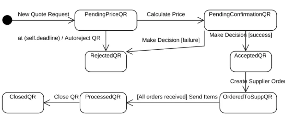
Fig. 4. State machine diagram for artifactQuoteRequest.
On the other hand, artifactQuoteRequesthas a more complex state machine diagram. First of all, it has a multi-level hierarchy. More specifically, it has three different levels. The first level has constraintsdisjointandcomplete, but the second and third levels are incomplete. In the first-level hierarchy, the states are: PendingPriceQR, PendingConfirmationQR,RejectedQR andAcceptedQR. AlthoughAcceptedQRhas two subclasses, it is included because the hierarchy is incomplete, and therefore, there can exist anAcceptedQRwhich has no subtypes. When a customer wishes to make a quote request, New Quote Request event executes and creates a QuoteRequest in state PendingPriceQR. This PendingPriceQR has an attribute,deadline, which establishes the last day in which the customer is wishing to wait for a price. If this deadline is not met, then the PendingPriceQR is automatically rejected and changes its state to RejectedQR. Notice thatat(self.deadline) is a time event, which results in the execution of effectAutoreject QR.
On the other hand, if the price for the request is established on time, it changes its state toPendingConfirmationQR, as now the quote request is waiting for the customer to decide whether he accepts the price or not. In both cases, event Make Decision executes, and depending on the outcome of this event,
the quote request changes its state to AcceptedQR (condition success) or to RejectedQR (conditionfailure). Eventually, anAcceptedQR will be processed (eventCreate Supplier Order) and the requested CDs ordered to the supplier, prompting a change of state toOrderedToSuppQR.
AnOrderedToSuppQR will change state to ProcessedQR when it is sent to the customer (eventSend Items). Notice that this will only happen when the condition2 is met: all the orders containing products in the quote request must
have been received. Finally, the quote request is closed (state ClosedQR) after the customer receives the order, indicated byClose QRevent.
3.3 Activity Diagrams
As we have explained previously, each external event in the state machine dia-gram would have the corresponding activity diadia-gram showing its details. Bearing this in mind, for the state machine diagram of Order, we would have the fol-lowing activity diagrams: New Order, Send to Supplier, Receive Order. For the state machine diagram of QuoteRequest, we would have the following activ-ity diagrams:New Quote Request, Calculate Price, Make Decision,Create Supplier Order,Send Items,Close QR.
As there are many activity diagrams, we will focus on those that are more use-ful to illustrate the characteristics of our approach. In particular, we will look at the following diagrams:Create Supplier Order,Send Items,Make Decision. The rest of diagrams can be found in the appendix at the end.
Create Supplier Order. Figure 5 depicts the activity diagram of Create Supplier Order. It first starts the order creation process, and afterwards it manages the assignment of the items in an AcceptedQR to the rightOrder. As each CD is provided by one supplier, the activity diagram checks if there is an OpenOrder for the given supplier. If there is not, it calls activity diagram New Order. In any case, it obtains the OpenOrder and links it to the current QuoteRequest. When there are no CDs left to process, the activity diagram ends.
Notice that the node in charge of creating the new order is in fact asubprocess
and it is decomposed in another activity diagram, as indicated by the rake-like symbol on the right-hand side of the node. In fact, this activity diagram corresponds to eventNew Orderin the state machine diagram of Order. In this particular example, this is how the evolution of the two artifacts is related: when linking the quote request to a supplier order, if there is no available order for the required supplier, a new order is created.
Send Items. Figure 6 shows the activity diagram for eventSend Itemsin the state machine diagram of Quote Request. It represents the process of sending the CDs, once they have been received from the supplier(s), to the customer.
2
Condition “All orders received” is defined in OCL as:self.order -> forAll(o |
12 Montserrat Estañol et al. New Quote Request
Calculate Price
Make Decision
Create Supplier Order
Send Items New Order Send to Supplier Receive Order Close QR Add CD Create QuoteRequest Evalute QR and set price Accept QuoteRequest Reject QuoteRequest
Start Order Creation
<<material>> Obtain Items from
Warehouse
<<material>> Pack Items
<<material>>
Send Package Mark as Sent
Create New Order
Close Order
<<material>>
Send to Supplier Register Expected Delivery
<<material>> Check Order <<material>> Notify Supplier Register Order as Received Add to Existing Order New Order Exists OpenOrder Close QuoteRequest [CDs left to process]
[no CDs left to process] [false] [true] <<fail>> <<succeed>> [all items] [missing items] <<succeed>> <<fail>> [reject] [accept] [more CDs to add]
[no more CDs to add]
Visual Paradigm for UML Community Edition [not for commercial use]
Fig. 5.Activity diagram of Create Supplier Order.
First of all, the necessary items for the quote request are picked up from the warehouse (Obtain Items from Warehouse). After this, they are packed up and sent to the customer (Pack Items and Send Package). Once they have been physically sent, the quote request is marked as sent. Notice that this event is made up of three material actions and one task. The three actions represent particular physical tasks that are carried out in the process but that do not directly make changes to the system. The only task that makes changes to the system is the last one,Mark as Sent.
New Quote Request
Calculate Price
Make Decision
Create Supplier Order
Send Items New Order Send to Supplier Receive Order Close QR Add CD Create QuoteRequest Evalute QR and set price Accept QuoteRequest Reject QuoteRequest
Start Order Creation
<<material>> Obtain Items from
Warehouse
<<material>> Pack Items
<<material>>
Send Package Mark as Sent
Create New Order
Close Order
<<material>>
Send to Supplier Register Expected Delivery
<<material>> Check Order <<material>> Notify Supplier Register Order as Received Add to Existing Order New Order Exists OpenOrder Close QuoteRequest [CDs left to process]
[no CDs left to process]
[false] [true] <<fail>> <<succeed>> [all items] [missing items] <<succeed>> <<fail>> [reject] [accept] [more CDs to add]
[no more CDs to add] Visual Paradigm for UML Community Edition [not for commercial use]
Fig. 6. Activity diagram of Send Items.
Make Decision. We include a final diagram in Figure 7 to illustrate the use of stereotypes in the activity diagram and how they connect to the state ma-chine diagram. The activity diagram corresponds to event Make Decision of QuoteRequest. It basically represents the user’s decision to either accept the quote request or to reject it. Depending on the user’s decision, either taskAccept QuoteRequest or task Reject QuoteRequest executes. The activity diagram ends in stereotype succeedin the first case orfail in the second, which con-nect directly with the event-dependent conditions in the state machine diagram of QuoteRequest.
New Quote Request
Calculate Price
Make Decision
Create Supplier Order
Send Items New Order Send to Supplier Receive Order Close QR Add CD Create QuoteRequest Evalute QR and set price Accept QuoteRequest Reject QuoteRequest
Start Order Creation
<<material>> Obtain Items from
Warehouse
<<material>> Pack Items
<<material>>
Send Package Mark as Sent
Create New Order
Close Order
<<material>>
Send to Supplier Register Expected Delivery
<<material>> Check Order <<material>> Notify Supplier Register Order as Received Add to Existing Order New Order Exists OpenOrder Close QuoteRequest [CDs left to process]
[no CDs left to process]
[false] [true] <<fail>> <<succeed>> [all items] [missing items] <<succeed>> <<fail>> [reject] [accept] [more CDs to add]
[no more CDs to add] Visual Paradigm for UML Community Edition [not for commercial use]
3.4 Operation Contracts
This section presents the OCL operation contracts of some of the tasks in our example. In particular, it will focus on the tasks that belong to activity diagram Make Decision and on the specification of the only effect that we have in the state machine diagram of QuoteRequest:Autoreject QR.
Listing 1. Code for taskAcceptQuoteRequest
action AcceptQuoteRequest ( quoteID : Natural )
localPre: -localPost:
let quote : QuoteRequest =
QuoteRequest . allInstances () -> select ( qr | qr . id = quoteID ) in
quote . oclIsTypeOf ( AcceptedQR ) and not
( quote . oclIsTypeOf ( PendingConfirmationQR )) and
quote . oclAsType ( AcceptedQR ). date = today () and
quote . oclAsType ( AcceptedQR ). finalPrice =
quote@pre . oclAsType ( PendingConfirmationQR ). finalPrice
Listing 1 shows the operation contract of serviceAccept QuoteRequest. It has as input parameter the quoteID of the QuoteRequest that the customer wishes to accept. Then the service changes the state of the QuoteRequest to AcceptedQR and stores the final price and the date in which theQuoteRequest has been accepted.
Listing 2. Code for taskRejectQuoteRequest
action RejectQuoteRequest ( quoteID : Natural , reason :String)
localPre: -localPost:
let quote : QuoteRequest =
QuoteRequest . allInstances () -> select ( qr | qr . id = quoteID ) in
quote . oclIsTypeOf ( RejectedQR ) and not
quote . oclIsTypeOf ( PendingConfirmationQR )) and
quote . oclAsType ( RejectedQR ). date = today () and
quote . oclAsType ( RejectedQR ). reason = reason
Listing 2 shows the OCL code forReject QuoteRequest. Given a quoteID identifying a QuoteRequest and a reason for the rejection as input, it changes theQuoteRequest to state RejectedQR, storing the date in which the decision was made and the reason for the rejection (given as input).
Finally, we believe it is interesting to look at the specification ofAutoreject QR. Remember that this effect executes when time event at(self.deadline) takes place, that is, when the deadline established by the customer is reached and aPendingPriceQRhas not changed its state because the shop has not established a price.
Listing 3 shows the OCL code for the effect. It has as input the quote re-quest which has reached the deadline, and the postcondition changes its state to RejectedQR stating the reason for the change.
14 Montserrat Estañol et al.
Listing 3.Code for taskAutorejectQR
action RejectQuoteRequest ( quote : QuoteRequest )
localPre: -localPost:
quote . oclIsTypeOf ( RejectedQR ) and not
( quote . oclIsTypeOf ( PendingPriceQR )) and
quote . oclAsType ( RejectedQR ). date = today () and
quote . oclAsType ( RejectedQR ). reason =‘‘ Deadline reached ’’
4 Related Work
In this section we analyze different alternatives to represent business process models. We first begin by examining process-centric approaches, and afterwards we look at artifact-centric alternatives.
4.1 Process-centric Approaches
There are several languages available to represent business process models fol-lowing a traditional, or process-centric, approach. One of the most well-known is probably BPMN (Business Process Modeling Notation); however, there are several others such as UML activity diagrams, Workflow nets or YAWL (Yet Another Workflow Language) [20]. Although some of these languages have the ability to represent the data needed in the flow, their focus is on the sequenc-ing of the tasks that are carried out in the process. DFDs (data-flow diagrams) would be one example of this. Although they place high importance on the data, the focus is on how these data move in the process, from one task to next, and little importance is given to their details or on the precise meaning of the tasks [21].
Another well-known language is BPEL (Business Process Execution Lan-guage). However, it is meant to be a web-service composition language following XML notation, and our focus is on defining processes at a high level of abstrac-tion.
There are some process-centric works that do take data into consideration. For instance, [22] represents the associations between services in a WFD-net (WorkFlow nets annotated with Data). The tasks are annotated with the data that is created, read or written by the task. Similarly, [23] uses WSM nets which represent both the control flow and the data flow, although the data flow is lim-ited to read and write dependencies between activities and data. [24] represents associations in an operational model, which shows tasks (or services) as nodes connected using arrows or edges. The operational model also shows the transfer of artifacts between tasks by indicating them over the edges. However, details of artifacts are not shown.
4.2 Artifact-centric Approaches
After giving an overview of process-centric approaches, we will deal with works that specify business processes from an artifact-centric perspective.To facilitate the analysis, this subsection is structured according to the dimensions of the BALSA framework for easier readability and comparison. At the end of the subsection we include a table which summarizes our analysis.
Business Artifacts Business artifacts can be represented in several ways. Many
authors opt for a database schema [25, 11, 26, 27, 7], while others consider artifacts as a set of attributes or variables [28, 12, 29, 3]. Another alternative is to add an ontology represented by means of description logics on top of a relational database [30]. Although some of these alternatives describe the artifacts in a formal way, none of them represent the artifacts in a graphical way. This has some disadvantages: the models are more difficult to understand, e.g. it is more difficult to see how the artifacts relate to one another and to other objects.
There are also many works that represent artifacts in a graphical and formal way. For instance, [4, 5, 6] represent the business artifact and its lifecycle in one model, GSM, that includes the artifact’s attributes. However, the relation-ships between artifacts are not made explicit. On the other hand, [31] represents artifacts as state machine diagrams defined by Petri nets, but does not give de-tails on how the attributes of an artifact are represented. Closer to a UML class diagram is the Entity-Relationship model used in [32]. [16] uses a UML class diagram. Both the ER diagram and the UML class diagram are graphical and formal (or semi-formal) alternatives.
Finally, [8] defines its own framework, the PHILharmonicFlows, which uses a diagram that falls in-between a UML diagram and a database schema repre-sentation. Although it is a semi formal representation, it has the drawback of not using any well-known languages.
Lifecycles The lifecycle of a business artifact may be implicitly represented by
using dynamic constraints in logic [25] or the tasks (or actions in the terminology of the papers) that make changes to the artifacts [26, 27, 11, 30]. [7] derives the artifact’s lifecycle from a BPMN model annotated with data.
In this context, however, we are interested in approaches that represent the lifecycles explicitly. In many cases, such as [32], they are based on state machine diagrams, as they show very clearly the states in the evolution of the artifact and how each state is reached and under which conditions.
The GSM approach is a similar alternative to state machine diagrams, as it also represents in a graphical way the stages in the evolution of an artifact and the guard conditions, but adding the concept of milestone to them. A milestone is a condition that, once it is fulfilled, it closes a state. Another difference with state machine diagrams is that the sequencing of stages is determined by the guard conditions and not by edges connecting the states, making it much less straightforward than state machine diagrams. However, it is possible to use edges
as a macro. GSM was first defined in [4] and further studied and formalized in
16 Montserrat Estañol et al.
Another alternative to represent lifecycles is to use variants of Petri nets [16, 31, 33]. These representations are both graphical and formal. [8], within the PHILharmonicsFlows framework, uses a micro process to represent the evolution of an artifact and its states, which results in a graphical representation similar to GSM, without its strong formality.
Finally, some works opt for using a variable to store the artifact’s state [12, 28]. Although it is an explicit representation, it only stores the current state of the artifact, instead of showing how it will evolve from one stage to the next. Therefore, it is a poorer form of representation in contrast to state machine diagrams, variants of Petri nets or GSM.
Associations In general, the different ways of representing associations can be
classified on whether they represent them graphically or not. Many non-graphical alternatives are based on variants on condition-action rules. These alternatives have one main disadvantage over graphical ones: in order to know the order in which the tasks can execute, it will be necessary to carefully examine the rules. In contrast, graphical alternatives are easier to understand at a glance.
For instance, [25, 11, 27, 30] use a set of condition-action rules defined in logic. In [12], preconditions determine the execution of the actions; as such, they act as associations. As they are defined in logic, they are formal and unambiguous. Likewise, [32] uses event-condition-action rules, but they are defined in nat-ural language. Using natnat-ural language makes them easier to understand than those defined in logic, but they have a severe drawback: they are not formal and because of this they may have ambiguities and errors.
Alternatively, [16] useschannels to define the connections betweenproclets. A proclet is a labeled Petri net with ports that describes the internal lifecycle of an artifact. On the other hand, DecSerFlow allows specifying restrictions on the sequencing of tasks, and it is used in [33]. It is a language grounded on temporal logic but also includes a graphical representation.
When it comes to graphical representations, [8] uses micro and macro pro-cesses to represent the associations between the services. [7] uses a BPMN di-agram to represent the associations between the tasks. In this sense, it is very similar to our proposal to use UML activity diagrams. All these approaches are graphical and formal.
In contrast, [3, 2] opt for a graphical representation using flowcharts and, because of this, the resulting models can be easily understood. However, they do not use any particular language to define the flow and they do not define the semantics of flowchart.
Services Services are also referred to as tasks or actions in the literature. In
general, they are described by using pre and postconditions (also called effects). Different variants of logic are used in [25, 11, 12, 28, 29, 26, 30] for this purpose. [27, 5] omit the preconditions. The use of logic implies that the definition of services is precise, formal and unambiguous, but it is hardly understandable by the people involved in the business process.
Conversely, [32] uses natural language to specify pre and postconditions. In contrast to logic, natural language is easy to understand, but it is an informal description of services: this implies that the service definition may be ambiguous and error-prone.
Finally, [7] expresses the preconditions and postconditions of services by means of data objects associated to the services. These data objects are an-notated with additional information such as what is read or written. [8] defines “micro steps” in the stages of their model which correspond to attributes that are modified. Neither of this two proposals are as powerful as using logic nor OCL operation contracts.
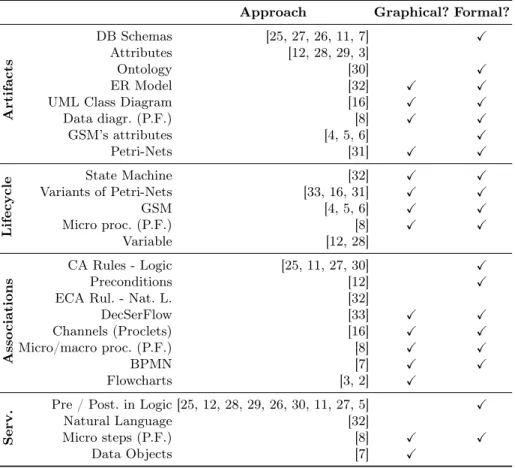
Table 1. Overview of alternative representations of data-centric process models. P.F
stands forPHILharmonicFlows
Approach Graphical? Formal?
Artifacts
DB Schemas [25, 27, 26, 11, 7] X
Attributes [12, 28, 29, 3]
Ontology [30] X
ER Model [32] X X
UML Class Diagram [16] X X
Data diagr. (P.F.) [8] X X GSM’s attributes [4, 5, 6] X Petri-Nets [31] X X Lifecycle State Machine [32] X X Variants of Petri-Nets [33, 16, 31] X X GSM [4, 5, 6] X X Micro proc. (P.F.) [8] X X Variable [12, 28] Asso ciations CA Rules - Logic [25, 11, 27, 30] X Preconditions [12] X
ECA Rul. - Nat. L. [32]
DecSerFlow [33] X X Channels (Proclets) [16] X X Micro/macro proc. (P.F.) [8] X X BPMN [7] X X Flowcharts [3, 2] X Serv.
Pre / Post. in Logic [25, 12, 28, 29, 26, 30, 11, 27, 5] X
Natural Language [32]
Micro steps (P.F.) [8] X X
Data Objects [7] X
Summary To conclude this section, Table 1 shows a summary of the
artifact-centric approaches. As the table shows, none of the analyzed approaches uses the same language to represent all these dimensions in artifact-centric business
18 Montserrat Estañol et al.
processes. In many cases, the chosen system of representation is not graphical, which makes the models more difficult to understand. To complicate matters further, in many instances the language that is used is grounded on logic. Al-though formal, it is not understandable by business people. Natural language, on the other hand, is not a good option either: it can be easily understood, but it may lead to ambiguities and errors.
5 Conclusions
In this paper we have presented a methodology to model business process models from an artifact-centric perspective. To do so we have used the BALSA frame-work as a basis, proposing a different model for each dimension in the frameframe-work. As we have seen, the artifact-centric approach to business process modeling con-siders the data needed by the process, and because of this, it is possible to define formally the meaning of the tasks in the process.
To represent the diagrams in the example we have opted for a combination of models using the UML and OCL languages, because they integrate naturally and they give an homogeneous view (as it uses the same language) for the business. These languages can be understood by domain experts and they provide a high level of abstraction. Another advantage of using these combination of models is that, as we have shown in previous work [9], it is possible to perform semantic reasoning on the models to ensure that they fulfill the user requirements.
However, as long as the semantics of our models are respected, other alter-natives are viable, with the same results, as we have outlined in this paper. Moreover, it is also possible to establish restrictions over these models to ensure that the verification that can be performed on them is decidable [10].
We have illustrated our approach by means of an example based on a CD online shop. This complexity in this example lies in the fact that there is a many-to-many relationship between the two artifacts in the model.
As further work, we would like to create a tool that given these set of models, is able to automatically check their correctness. In addition, it would also be interesting to carry out user-defined tests for those requirements that cannot be directly inferred from the model.
Acknowledgements
This work has been partially supported by the Ministerio de Ciencia e Innovación under project TIN2011-24747 and by Universitat Politècnica de Catalunya.
References
1. Hull, R.: Artifact-centric business process models: Brief survey of research results and challenges. In Meersman, R., Tari, Z., eds.: OTM 2008. Volume 5332 of LNCS. Springer Berlin / Heidelberg (2008) 1152–1163
2. Bhattacharya, K., Caswell, N.S., Kumaran, S., Nigam, A., Wu, F.Y.: Artifact-centered operational modeling: lessons from customer engagements. IBM Syst. J.
46(4) (October 2007) 703–721
3. Nigam, A., Caswell, N.S.: Business artifacts: an approach to operational
specifica-tion. IBM Syst. J.42(3) (2003) 428–445
4. Hull, R., et al.: Introducing the Guard-Stage-Milestone Approach for Specifying Business Entity Lifecycles. In Bravetti, M., Bultan, T., eds.: WS-FM 2010. Volume 6551 of LNCS. (2011) 1–24
5. Damaggio, E., Hull, R., Vaculín, R.: On the equivalence of incremental and fix-point semantics for business artifacts with Guard – Stage – Milestone lifecycles.
Information Systems38(4) (2013) 561 – 584 Special section on BPM 2011
confer-ence.
6. Hull, R., et al.: Business artifacts with guard-stage-milestone lifecycles: managing artifact interactions with conditions and events. In Eyers, D.M., Etzion, O., Gal, A., Zdonik, S.B., Vincent, P., eds.: DEBS, ACM (2011) 51–62
7. Meyer, A., Pufahl, L., Fahland, D., Weske, M.: Modeling and enacting complex data dependencies in business processes. In Daniel, F., Wang, J., Weber, B., eds.: Business Process Management - 11th International Conference, BPM 2013, Bei-jing, China, August 26-30, 2013. Proceedings. Volume 8094 of Lecture Notes in Computer Science., Springer (2013) 171–186
8. Künzle, V., Reichert, M.: Philharmonicflows: towards a framework for object-aware
process management. Journal of Software Maintenance23(4) (2011) 205–244
9. Estañol, M., Sancho, M., Teniente, E.: Reasoning on UML data-centric business process models. In Basu, S., Pautasso, C., Zhang, L., Fu, X., eds.: Service-Oriented Computing - 11th International Conference, ICSOC 2013, Berlin, Germany, De-cember 2-5, 2013, Proceedings. Volume 8274 of Lecture Notes in Computer Sci-ence., Springer (2013) 437–445
10. Calvanese, D., Montali, M., Estañol, M., Teniente, E.: Verifiable UML artifact-centric business process models. In Li, J., Wang, X.S., Garofalakis, M.N., Soboroff, I., Suel, T., Wang, M., eds.: CIKM 2014, ACM (2014) 1289–1298
11. Bagheri Hariri, B., et al.: Verification of relational data-centric dynamic systems with external services. In: PODS, ACM (2013) 163–174
12. Damaggio, E., Deutsch, A., Vianu, V.: Artifact systems with data dependencies
and arithmetic. ACM Trans. Database Syst.37(3) (2012) 22
13. Gerede, C.E., Su, J.: Specification and verification of artifact behaviors in business process models. In Krämer, B.J., Lin, K.J., Narasimhan, P., eds.: ICSOC 2007. Volume 4749 of LNCS., Springer (2007) 181–192
14. Estañol, M., Queralt, A., Sancho, M.R., Teniente, E.: Artifact-centric business pro-cess models in UML. In La Rosa, M., Soffer, P., eds.: Business Propro-cess Management Workshops 2012. Volume 132 of LNBIP., Springer (2013) 292–303
15. Estañol, M., Queralt, A., Sancho, M.R., Teniente, E.: Using UML to
spec-ify artifact-centric business process models. In: BMSD 2014 : Proceedings of
the Fourth International Symposium on Business Modeling and Software Design, SciTePress (2014) 84–93
16. Fahland, D., Leoni, M.D., van Dongen, B.F., van der Aalst, W.M.P.: Behavioral conformance of artifact-centric process models. In Abramowicz, W., ed.: BIS 2011. Volume 87 of LNBIP., Springer (2011) 37–49
17. Olivé, A.: Conceptual Modeling of Information Systems. Springer, Berlin (2007) 18. ISO: ISO/IEC 19505-2:2012 - OMG UML superstructure 2.4.1 (2012) Available
at:http://www.iso.org/iso/iso_catalogue/catalogue_tc/catalogue_detail.
20 Montserrat Estañol et al.
19. Queralt, A., Teniente, E.: Specifying the semantics of operation contracts in con-ceptual modeling. In: Journal on Data Semantics VII. Volume 4244 of LNCS. Springer Berlin / Heidelberg (2006) 33–56
20. Weske, M.: Business Process Management: Concepts, Languages, Architectures. Springer, Berlin Heidelberg (2007)
21. Yourdon, E.: Just enough structured analysis (2006) Available at: http://www.
yourdon.com/jesa/pdf/JESA_p.pdf.
22. Trcka, N., Aalst, W.M.P.V.D., Sidorova, N.: Data-Flow Anti-patterns : Discovering Data-Flow Errors in Workflows. In van Eck, P., Gordijn, J., Wieringa, R., eds.: CAiSE 2009. Volume 5565 of LNCS. (2009) 425–439
23. Ly, L.T., Rinderle, S., Dadam, P.: Semantic Correctness in Adaptive Process
Management Systems. In Dustdar, S., Fiadeiro, J., Sheth, A., eds.: BPM 2006. Volume 4102 of LNCS., LNCS (2006) 193–208
24. Liu, R., Bhattacharya, K., Wu, F.Y.: Modeling Business Contexture and Behavior Using Business Artifacts. In Krogstie, J., Opdahl, A., Sindre, G., eds.: CAiSE 2007. Volume 4495 of LNCS., Springer (2007) 324–339
25. Bagheri Hariri, B., Calvanese, D., De Giacomo, G., De Masellis, R., Felli, P.: Foun-dations of relational artifacts verification. In Rinderle-Ma, S., Toumani, F., Wolf, K., eds.: BPM 2011. Volume 6896 of LNCS., Springer (2011) 379–395
26. Belardinelli, F., Lomuscio, A., Patrizi, F.: Verification of deployed artifact systems via data abstraction. In Kappel, G., Maamar, Z., Nezhad, H.R.M., eds.: ICSOC 2011. Volume 7084 of LNCS., Springer Berlin Heidelberg (2011) 142–156
27. Cangialosi, P., Giacomo, G.D., Masellis, R.D., Rosati, R.: Conjunctive artifact-centric services. In Maglio, P.P., Weske, M., Yang, J., Fantinato, M., eds.: ICSOC 2010. Volume 6470 of LNCS., Springer (2010) 318–333
28. Bhattacharya, K., Gerede, C., Hull, R., Liu, R., Su, J.: Towards formal analysis of artifact-centric business process models. In Alonso, G., Dadam, P., Rosemann, M., eds.: BPM 2007. Volume 4714 of LNCS., Springer (2007) 288–304
29. Fritz, C., Hull, R., Su, J.: Automatic construction of simple artifact-based business processes. In Fagin, R., ed.: ICDT 2009. Volume 361., ACM (2009) 225–238 30. Calvanese, D., Giacomo, G.D., Lembo, D., Montali, M., Santoso, A.:
Ontology-based governance of data-aware processes. In Krötzsch, M., Straccia, U., eds.: RR. Volume 7497 of LNCS., Springer (2012) 25–41
31. Lohmann, N., Wolf, K.: Artifact-Centric Choreographies. In Maglio, P.P., Weske, M., Yang, J., Fantinato, M., eds.: ICSOC 2010. Volume 6470 of LNCS., Springer (2010) 32–46
32. Bhattacharya, K., Hull, R., Su, J.: A Data-Centric Design Methodology for Busi-ness Processes. In: Handbook of Research on BusiBusi-ness Process Management. (2009) 1–28
33. Kucukoguz, E., Su, J.: On lifecycle constraints of artifact-centric workflows. In Bravetti, M., Bultan, T., eds.: WS-FM 2010. Volume 6551 of LNCS., Springer (2011) 71–85
Appendices
A Specification of the Whole Example
This appendix presents the whole specification of the example following our approach. For easier reference, we include again the class diagram, state machine diagrams and activity diagrams (with the respective operation contracts) for those elements already described in the paper.
1 Class Diagram
Figure 8 shows the class diagram for our example. There are two business ar-tifacts: QuoteRequestand Order, as shown by the stereotypes. The rest of the classes in the diagram, such as Supplier, Customer or CD represent objects: relevant information for the business but whose evolution we do not track. Each artifact has its own identifier, in this case, for bothQuoteRequestandOrderthe identifier isid. The rest of classes in the diagram may also have their identifiers, for instance, aCD is identified by both its nameand author. Each artifact and object has as many attributes and relationships as relevant for the business.
Artifact Order is the simpler of the two. It has three different subclasses: OpenOrder, ClosedOrder and ReceivedOrder which contain the relevant in-formation for that particular state of the artifact. An OpenOrderis waiting to be sent to the supplier and additionalQuoteRequests can be assigned to it. A ClosedOrder has already been sent to the supplier. Finally, an Order changes its state toReceivedOrderwhen it has been received at the shop.
On the other hand, artifact QuoteRequest has a first level of sub-classes which are PendingPriceQR,PendingConfirmationQR, AcceptedQR and RejectedQR. A PendingPriceQR is waiting for the shop to quote the price. A PendingConfirmationQRhas already a price and is waiting for the customer’s acceptance or rejection. An AcceptedQR has already been accepted by the cus-tomer. In contrast,RejectedQR has been rejected.
AcceptedQR has one subclass:OrderedToSuppQR. Notice that the hierarchy is incomplete. An OrderedToSuppQRhas already been split into severalOrders that will eventually be processed and sent to the suppliers. At the same time, OrderedToSuppQRhas two subclasses:ProcessedQR andClosedQR, and the hi-erarchy is incomplete. Like in the previous case, an OrderedToSuppQRmay not have any of the subtypes. ProcessedQRrepresents a quote request that has al-ready been sent to the customer, and aClosedQRcorresponds to a quote request that has already been received by him or her.
24 name author CD id sentDate <<artifact>> QuoteRequest id name address Customer name Supplier id creationDate <<artifact>> Order date finalPrice AcceptedQR date OrderedToSuppQR quantity RequestedCD date reason RejectedQR deliveredOn ClosedQR date expectedDelivery ClosedOrder date expectedReception trackingNr ProcessedQR date ReceivedOrder finalPrice PendingConfirmationQR deadline PendingPriceQR lastUpdate OpenOrder notificationDate UnavailableCD * 1 supplies 1..* 0..1 * 1 1..* 1..* * 1..* * 1 /includes {incomplete}
quote state {disjoint, complete}
{disjoint, complete} order state
orderedToSupp state {disjoint, incomplete} {incomplete} < is divided into
requested at
< makes < includes
1. Identifiers: (QuoteRequest, id), (Customer, id), (CD, name+author), (Supplier, name), (Order, id)
2. A ProcessedQR may not have more than one Order for the same Supplier.
3. Derived Relationship includes: A RequestedCD will be related to an Order if the QuoteRequest of the RequestedCD is linked to an Order requested at its CD Supplier. 4. There can only be at most one OpenOrder per Supplier.
5. The Orders into which a ProcessedQR is divided must be to Suppliers who provide the CDs included in the ProcessedQR.
6. The sentDateof a QuoteRequestmust be earlier than attribute datein any of the subclasses ofQuoteRequest.
7. QuoteRequest.sentDate <PendingPriceQR.deadline
8. AcceptedQR.date ≤ OrderedToSuppQR.date
9. OrderedToSuppQR.date≤ ProcessedQR.date
10. ProcessedQR.date≤ ClosedQR.deliveredOn
11. The creation date of Order must be earlier or equal to attribute datein any of its subclasses.
12. Order.creationDate≤ OpenOrder.lastUpdate
Fig. 8.Class diagram showing the business artifacts as classes with the corresponding integrity constraints
2 State Machine Diagrams
ClosedOrder ReceivedOrder OpenOrder Send to Supplier Receive Order [success]
New Order
Fig. 9. State machine diagram for artifactOrder.
Figures 9 and 10 show the state machine diagrams that correspond to the business artifacts in this example: Order andQuoteRequest. We will begin by looking at the state machine diagram forOrder, which is simpler. In this case, there is a single-level hierarchy in the class diagram with restrictionsdisjoint and complete, therefore the states exactly map to the subclasses in the class diagram. An Order is created when there is a request to create a new or-der, as shown by event New Order. This order remains in state OpenOrder
25
ClosedQR ProcessedQR OrderedToSuppQR
RejectedQR AcceptedQR
PendingConfirmationQR PendingPriceQR
at (self.deadline) / Autoreject QR
Close QR [All orders received] Send Items
Create Supplier Order Make Decision [failure] Make Decision [success]
Calculate Price New Quote Request
Fig. 10. State machine diagram for artifactQuoteRequest.
until someone decides that the order can be made to supplier, by executing eventSend to Supplier. Then the order becomes aClosedOrderand no more AcceptedQRs can be linked to it. Finally, once the order is received, if event Receive Order executes successfully, as indicated by tag success, it changes its state toReceivedOrder.
On the other hand, artifactQuoteRequesthas a more complex state machine diagram. First of all, it has a multi-level hierarchy. More specifically, it has three different levels. The first level has constraintsdisjointandcomplete, but the second and third levels are incomplete. In the first-level hierarchy, the states are: PendingPriceQR, PendingConfirmationQR,RejectedQR andAcceptedQR. AlthoughAcceptedQRhas two subclasses, it is included because the hierarchy is incomplete, and therefore, there can exist anAcceptedQRwhich has no subtypes. When a customer wishes to make a quote request, New Quote Request event executes and creates a QuoteRequest in state PendingPriceQR. This PendingPriceQR has an attribute,deadline, which establishes the last day in which the customer is wishing to wait for a price. If this deadline is not met, then the PendingPriceQR is automatically rejected and changes its state to RejectedQR. Notice thatat(self.deadline) is a time event, which results in the execution of effectAutoreject QR.
On the other hand, if the price for the request is established on time, it changes its state toPendingConfirmationQR, as now the quote request is wait-ing for the customer to decide whether he accepts the price or not. In both cases, event Make Decision executes, and depending on the outcome of this event, the quote request changes its state toAcceptedQR(conditionsuccess) or to RejectedQR (condition fail). Eventually, an AcceptedQR will be processed (eventCreate Supplier Order) and the requested CDs ordered to the supplier, prompting a change of state toOrderedToSuppQR.
AnOrderedToSuppQR will change state to ProcessedQR when it is sent to the customer (eventSend Items). Notice that this will only happen when the condition3 is met: all the orders containing products in the quote request must
3 Condition “All orders received” is defined in OCL as:self.order -> forAll(o |
26
have been received. Finally, the quote request is closed (state ClosedQR) after the customer receives the order, indicated byClose QRevent.
3 Activity Diagrams and Operation Contracts
New Quote Request
Add CD Create QuoteRequest [more CDs to add]
[no more CDs to add]
Fig. 11. Activity diagram ofNew Quote Request.
New Quote Request New Quote Requestis in charge of creating a new quote request, and while there are CDs to add to the QuoteRequest, it keeps adding them.
Create QuoteRequest
action CreateQuoteRequest ( cust : String, quoteID : Natural ,
deadlineDate : Date )
localPre: not( QuoteRequest . allInstances () -> exists ( qr |
qr . id = quoteID ))
localPost: PendingPriceQR . allInstances () -> exists ( qr |
qr . oclIsNew () and qr . id = quoteID and qr . customer . id = cust and
qr . sentDate = today () and qr . deadline = deadlineDate )
TaskCreate QuoteRequestcreates a newQuoteRequestfor the given customer
and with the givenidanddeadline.
Add CD
action AddCD ( cdName : String, cdAuthor : String, qty : Natural ,
quoteID : Natural )
localPre: not( RequestedCD . allInstances () -> exists ( rcd |
rcd . cD . name = cdName and rcd . cD . author = cdAuthor and
rcd . quoteRequest . id = quoteID ))
localPost: RequestedCD . allInstances () -> exists ( rcd |
rcd . oclIsNew () and rcd . quantity = qty and
rcd . cD . author = cdAuthor and rcd . cD . name = cdName and
rcd . quoteRequest . id = quoteID )
Add CD adds the given CD (identified by cdName and cdAuthor) in the
27 Calculate Price Evalute QR and set price
Fig. 12. Activity diagram ofCalculate Price.
Calculate Price This activity diagram sets the price for theQuoteRequest.
Evaluate QR and Set Price
action EvaluateQRAndSetPrice ( quoteID : Natural , price : Real)
localPre: -localPost:
let quote : QuoteRequest =
QuoteRequest . allInstances () -> select ( qr | qr . id = quoteID ) in
quote . oclIsTypeOf ( PendingConfirmationQR ) and not
quote . oclIsTypeOf ( PendingPriceQR ) and
quote . oclAsType ( PendingConfirmationQR ). finalPrice = price
Task EvaluateQRAndSetPrice changes the state of the QuoteRequest to
PendingConfirmationQR and sets its price to the given inputprice.
Make Decision Activity diagram Make Decision shows the decision making process after the price has been set for theQuoteRequest. If the customer wishes to accept the price, taskAccept QuoteRequest executes. Otherwise, taskReject
QuoteRequest executes.
New Quote Request
Calculate Price
Make Decision
Create Supplier Order
Send Items New Order Send to Supplier Receive Order Close QR Add CD Create QuoteRequest Evalute QR and set price Accept QuoteRequest Reject QuoteRequest
Start Order Creation
<<material>> Obtain Items from
Warehouse
<<material>> Pack Items
<<material>>
Send Package Mark as Sent
Create New Order
Close Order
<<material>>
Send to Supplier Register Expected Delivery
<<material>> Check Order <<material>> Notify Supplier Register Order as Received Add to Existing Order New Order Exists OpenOrder Close QuoteRequest [CDs left to process]
[no CDs left to process]
[false] [true] <<fail>> <<succeed>> [all items] [missing items] <<succeed>> <<fail>> [reject] [accept] [more CDs to add]
[no more CDs to add] Visual Paradigm for UML Community Edition [not for commercial use]
Fig. 13. Activity diagram ofMake Decision.
Accept QuoteRequest
action AcceptQuoteRequest ( quoteID : Natural )
localPre: -localPost:
let quote : QuoteRequest =
28
quote . oclIsTypeOf ( AcceptedQR ) and not
( quote . oclIsTypeOf ( PendingConfirmationQR )) and
quote . oclAsType ( AcceptedQR ). date = today () and
quote . oclAsType ( AcceptedQR ). finalPrice =
quote@pre . oclAsType ( PendingConfirmationQR ). finalPrice
Task Accept QuoteRequest has as input parameter the quoteID of the
QuoteRequest that the customer wishes to accept. Then the service changes
the state of theQuoteRequest toAcceptedQR and stores the final price and the date in which theQuoteRequest has been accepted.
Reject QuoteRequest
action RejectQuoteRequest ( quoteID : Natural , reason :String)
localPre: -localPost:
let quote : QuoteRequest =
QuoteRequest . allInstances () -> select ( qr | qr . id = quoteID ) in
quote . oclIsTypeOf ( RejectedQR ) and not
quote . oclIsTypeOf ( PendingConfirmationQR )) and
quote . oclAsType ( RejectedQR ). date = today () and
quote . oclAsType ( RejectedQR ). reason = reason
Given aquoteID identifying aQuoteRequestand a reason for the rejection as input, taskRejectQuoteRequest changes theQuoteRequest to stateRejectedQR, storing the date in which the decision was made and the reason for the rejection (given as input).
Create Supplier Order Figure 14 depicts the activity diagram ofCreate
Sup-plier Order. It begins by starting the order creation process process. After this,
for each CD in the quote request, it checks if there is an open order to the sup-plier of the CD in question. If there is, it adds the CD to the order. Otherwise, it creates a new order and adds the CD to it. When there are no CDs left to process, the activity diagram ends.
Notice that the node in charge of creating the new order is in fact asubprocess
and it is decomposed in another activity diagram, as indicated by the rake-like symbol on the right-hand side of the node. In fact, this activity diagram corresponds to eventNew Order in the state machine diagram ofOrder. In this particular example, this is how the evolution of the two artifacts is related: when linking the quote request to a supplier order, if there is no available order for the required supplier, a new order is created.
Create Supplier Ordermanages the assignment of the items in anAcceptedQR
to the rightOrder. As each CD is provided by one supplier, the activity diagram checks if there is an OpenOrder for the given supplier. If there is not, it calls activity diagramNew Order. In any case, it obtains theOpenOrder and links it to the currentQuoteRequest.
![Fig. 1. Representation of the BALSA dimensions in our approach, adapted from [1]](https://thumb-us.123doks.com/thumbv2/123dok_us/9533004.2829412/4.918.209.612.120.347/fig-representation-balsa-dimensions-approach-adapted.webp)