TRANSPORTATION RESEARCH BOARD NATIONAL RESEARCH COUNCIL
R
ESEARCH
R
ESULTS
D
IGEST
November 1998—Number 232
Subject Area: IIC Bridges, Other Structures, Responsible Senior Program Officer: Edward T. Harrigan and Hydraulics and Hydrology
Report on the 1997 Scanning Review of
Asian Bridge Structures
This digest summarizes the the findings from NCHRP Project 20-36, “Highway Research and Technology—International Information Sharing,” conducted by a scanning review team of representatives from U.S. federal, state, and private sector
agencies. This digest was prepared by Henry G. Russell, Report Facilitator for the review.
SUMMARY
This digest describes the findings of an inter-national scanning tour undertaken to obtain a broad overview of bridge design, materials technology, construction procedures, and maintenance prac-tices in Asia. The scanning team focused on iden-tifying technological developments in Asia that have the potential for application in the United States. In addition, the team shared information with their international counterparts on U.S. prac-tices in highway bridge construction, maintenance, and management to promote international ex-change and cooperation.
The scanning tour concentrated on the follow-ing topics:
• Design standards, codes, and specifications; • Design and construction practices;
• Materials, fabrication, and joining techniques; • Bridge protection strategies;
• Inspection and rehabilitation practices; • Programming and management practices; and • Innovations.
The review was performed by an 11-member team representing several of the states, the Federal Highway Administration (FHWA), American
As-sociation of State Highway and Transportation Officials (AASHTO), and National Cooperative Highway Research Program (NCHRP). The scan-ning tour took place from September 12 through September 28, 1997, and involved visits to Japan, South Korea, and Taiwan.
In Japan, the team met with representatives of the Honshu-Shikoku Bridge Authority (HSBA), Public Works Research Institute (PWRI), Japan Highway Public Corporation (JH), Metropolitan Expressway Public Corporation (MEPC), Tokyo Institute of Technology, Nippon Steel Corporation, and Yokogawa Bridge Corporation. In South Ko-rea, the team met with representatives of the Korea Highway Corporation (KHC). In Taiwan, the team met with representatives of the Taiwan Area National Freeway Bureau and the Taiwan Area National Expressway Engineering Bureau of the Ministry of Transportation and Communications. In all three countries, site visits were made to major bridges.
On the basis of the observations made during the scanning review, the team developed a list of 30 topics for possible application in the United States. The list was then divided into 6 high-prior-ity topics, 7 medium-priorhigh-prior-ity topics, and 17 other topics for consideration at a later date.
CONTENTS Summary, 1 High-Priority Topics, 3 Medium-Priority Topics, 3 Other Topics, 3 Introduction, 3 Purpose, 3 Sponsoring Organizations, 4 Team Members, 4 Metric Equivalents, 4
Organizations and Site Visits, 4
Summary of Recommended Technologies, 13 High-Priority Topics, 13
Medium-Priority Topics, 14 Other Topics, 15
Design Standards, Codes, and Specifications, 18 Japan, 18
South Korea, 18 Taiwan, 19
Recommendations on Design Standards, Codes, and Specifications, 19 Design and Construction Practices, 19
Japan, 19 South Korea, 24 Taiwan, 25
Recommendations on Design and Construction Practices, 27 Materials, Fabrication and Joining Techniques, 27
Japan, 27 South Korea, 32 Taiwan, 33
Recommendations on Materials, Fabrication and Joining Techniques, 33 Bridge Protection Strategies, 33
Japan, 33 South Korea, 35 Taiwan, 35
Recommendations on Bridge Protection Strategies, 37 Inspection and Rehabilitation Practices, 37
Japan, 37 South Korea, 38 Taiwan, 38
Recommendations on Inspection and Rehabilitation Practices, 38 Programming and Management Practices, 39
Japan, 39 South Korea, 39 Taiwan, 39 Other Innovations, 39
Recommendations on Other Innovations, 40 Appendix A Amplifying Questions, 40 Appendix B Material Reviewed, 41 Appendix C Itinerary, 42
Appendix D Team Members, 43 Appendix E Acronyms, 43
Appendix F Selected Figure from CATS Brochure, 44 Acknowledgments, 45
High-Priority Topics
The following topics were identified as high-priority: • Dimple pipe for exterior of stay cables.
• Nonsegregating flowable concretes.
• A computerized assembly and test system (CATS) for steel components.
• Nonmetallic removable back-up bars for one-sided welding.
• Dry air injection system for corrosion protection of cables.
• Special paint primer.
Medium-Priority Topics
The following seven topics were identified as medium priority:
• Balanced cantilever construction with alternate seg-ments offset by 1/2-segment length.
• Full cantilever erection for end spans of balanced canti-lever bridges.
• Nonseparating (desegregating) tremie concretes. • 19-wire prestressing strands.
• Wrapping wire with interlocking cross section. • Flame or thermal spray metallizing.
• Translation of relevant sections of the HSBA specifica-tions into English.
Other Topics
The following 17 topics were identified for consider-ation at a later date:
• Research on punching shear failure.
• Bolted connections for earthquake resistance.
• Mechanical damping devices to control vibrations of steel towers.
• Forced vibration tests on completed bridges.
• Special railway expansion joints for flexible long-span bridges.
• Pneumatic caissons with remote control equipment for underwater construction.
• Slurry-wall construction for tower foundations. • High-strength silicon steel wire.
• Steels containing a higher percentage of nickel. • Vibration damping steel plates.
• Thermo-mechanical control processing or similar tech-nology.
• Truss elements that taper to I-sections at the end con-nections.
• HSBA paint system.
• Asphalt overlays for orthotropic steel decks.
• Built-in access and utilities for bridge inspection and maintenance.
• A repair robot for use in inaccessible areas. • Public relations programs for major projects.
The team recognizes that some of the technologies en-compassed by the topics listed above are already used to a limited extent in the United States. The observation of their use in other countries supports the viability of the tech-nology.
INTRODUCTION
Purpose
The purpose of the scanning tour was to conduct a broad overview of bridge design, materials technology, construction procedures and maintenance practices in Asia. The focus of the team’s review was to identify technological developments in Asia that have the poten-tial for application in the United States. In addition, the team shared information with their international coun-terparts on U.S practices in highway bridge construction, maintenance, and management to promote international exchange and cooperation.
The team’s review concentrated on the following gen-eral topics of interest:
• Design standards, codes, and specifications. • Design and construction practices.
• Materials, fabrication and joining techniques. • Bridge protection strategies.
• Inspection and rehabilitation practices. • Programming and management practices. • Innovations.
A separate section of this digest is devoted to each of the above topics. Recommendations on practices and tech-nologies that are unknown or rarely used in the United States are included at the end of each major section. The recom-mended practices and technologies are listed along with rec-ommendations for their implementation.
Prior to the trip, a list of amplifying questions on the above topics was developed by the team and submitted to the organizations that were visited. The list of ques-tions served to define the interests of the scanning tour and provided a basis for discussion at the formal meet-ings. The list of questions is included in Appendix A. In addition to the discussions held during the tour, the team was provided with numerous documents and references to other documents for further information. A list of documents reviewed for the preparation of this report is given in Appendix B. The itinerary for the scanning tour is contained in Appendix C.
Sponsoring Organizations
The technology scanning review of Asian bridges was conducted under the auspices of FHWA’s Office of Interna-tional Programs and NCHRP in cooperation with AASHTO. The American Road and Transportation Builders’ Associa-tion (ARTBA), the NaAssocia-tional Steel Bridge Alliance (NSBA) and the Portland Cement Association (PCA) provided input in the initial planning stages.
Team Members
The team members, along with the agencies that they represented, are listed below.
Name Representing Organization
Charles L. Chambers FHWA FHWA, Washington, DC
(Co-Chair)
James Siebels AASHTO Colorado DOT
(Co-Chair)
Ralph E. Anderson AASHTO Illinois DOT
John Formosa FHWA FHWA, Albany, NY
John M. Hooks FHWA FHWA, Washington, DC
John M. Kulicki NCHRP/ Modjeski and Masters,
ARTBA Inc.
Jerry L. Potter AASHTO Florida DOT
Henry G. Russell NCHRP Henry G. Russell, Inc. (Report Facilitator)
James E. Sothen AASHTO West Virginia Division
of Highways
William J. Wright FHWA FHWA, McLean, VA
George Y. Yamamoto AASHTO California DOT (Japan Only)
Appendix D provides biographical information on the team members.
Metric Equivalents
The primary units used in this report are based on the International System of Units (SI). However, since Japan, South Korea, and Taiwan still use the kilogram force sys-tem, some of the reported information has been retained in the original units to provide consistency with the original documentation.
Organizations and Site Visits
This section contains background information on the organizations visited and a summary of each site visit. Fur-ther details of relevant observations and information learned during team meetings and specific recommendations are given in subsequent sections.
Japan
In Japan, the team met with representatives of HSBA, PWRI, JH, MEPC, Tokyo Institute of Technology, Nippon Steel Corporation, and Yokogawa Bridge Corporation. Spe-cific site visits were made to the Akashi-Kaikyo Bridge, Kurushima Bridges, and Tatara Bridge. The team also ob-served and heard a description of the Seto-Ohashi Bridges. Visits were made to the Nippon Steel Corporation (Kimitsu Works) and Yokogawa Bridge Corporation (Chiba Plant).
Japan has at least four organizations responsible for the national highway system. JH is responsible for the system that is not under the jurisdiction of other authorities. Some of the major bridges of JH are listed in Table 1. These bridges were not visited by the team. MEPC is responsible for 248 km (154 mi) of expressway in the Tokyo metropoli-tan area. The Hanshin Expressway Corporation is
respon-TABLE 1 Major bridges of the Japan Highway Public Corporation
Length Maximum Span
Bridge Name Bridge Type m ft m ft Year Built
Beppu Myoban Concrete Arch 411 1,348 235 771 1989
Kanmon Suspension 1,068 3,504 712 2,336 1973
Meikou 3 Cable-Stayed 1,170 3,839 590 1,936 1998
Odawara Blue Way Extradosed Prestressed Concrete 270 886 120 394 1994
Tomie Asigara Concrete Cable-Stayed 785 2,575 185 607 1991
Okaya Viaduct Continuous Prestressed
Concrete Rigid Frame 1,489 4,885 148 486 1986
Katashina River Steel Truss 1,034 3,392 169 554 1985
Ueda Roman Solid Spandrel 715 2,346 54 177 1995
and Open Arch 37 121
Horonai River Steel Plate Girder
sible for the expressway system in the Osaka and Kobe met-ropolitan area. HSBA is responsible for bridges between the islands of Honshu and Shikoku.
HSBA was founded in 1970 to oversee the construction and operation of the toll highways and railways that link the islands of Honshu and Shikoku across the Seto Inland Sea. The three links are known as the Kobe-Naruto Route, Kojima-Sakaide Route and Onomichi-Imabari Route. The route names are based on the cities at the end of each link in Honshu and Shikoku. A listing of the major bridges on the three routes is given in Table 2. In addition, there are nu-merous approach structures and access ramps.
The Kobe-Naruto Route is the most eastern crossing and is partly complete. The route features a six-lane high-way. The crossing includes two suspension bridges—the Akashi-Kaikyo Bridge and the Ohnaruto Bridge. The Akashi-Kaikyo Bridge was almost complete at the time of the team’s visit. The Ohnaruto Bridge was open to traffic.
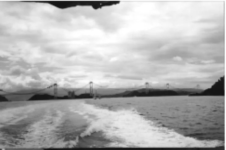
The Kojima-Sakaide Route is the central crossing and was completed in 1988. The crossing includes a suspension bridge (Shimotsui-Seto Bridge), two cable-stayed bridges (Hitsuishijima and Iwakurojima Bridges shown in Figure 1), and two suspension bridges (Kita Bisan-Seto and Minami Bisan-Seto Bridges shown in Figure 2). The upper deck of these bridges is used for a four-lane highway and the lower deck for a double-track railway. The bridges on the Kojima-Sakaide Route are known as the Seto-Ohashi Bridges.
The Onomichi-Imabari Route is the most western cross-ing and is partly complete. The route features a four-lane
highway. From north to south, it includes two parallel cable-stayed bridges (Onomichi and Shin Onomichi Bridges), a suspension bridge (Innoshima Bridge), a cable-stayed bridge (Ikuchi Bridge), a cable-stayed bridge (Tatara Bridge), an arch bridge (Ohmishima Bridge), a suspension bridge (Hakata-Ohshima Bridge), and three continuous suspension bridges (Kurushima Bridges). The route is scheduled for completion in 1999.
The Akashi-Kaikyo Bridge, shown in Figure 3, is a 3,910-m (12,828-ft)-long, three-span suspension bridge with span lengths of 960, 1,990, and 960 m (3,150, TABLE 2 Major bridges of HSBA
Route Bridge Type Spans(1) m
Kobe-Naruto Akashi-Kaikyo(2,3) Suspension 960, 1,990, 960
Ohnaruto Suspension 330, 876, 330
Kojima-Sakaide Shimotsui-Seto Suspension 230, 940, 230
Hitsuishijima Cable-Stayed 185, 420, 185
Iwakurojima Cable-Stayed 185, 420, 185
Kita Bisan-Seto Suspension 274, 990, 274
Minami-Bisan-Seto Suspension 274, 1,100, 274
Onomichi-Imabari Shin Onomichi Cable-Stayed 85, 215, 85
Onomichi Cable-Stayed 85, 215, 85 Innoshima Suspension 256, 770, 250 Ikuchi Cable-Stayed 150, 490, 150 Tatara(2,4) Cable-Stayed 270, 890, 320 Ohmishima Arch 297 Hakata-Ohshima Suspension 140, 560, 140 Kurushima 1(2) Suspension 190, 600, 170 Kurushima 2 Suspension 250, 1,020, 245 Kurushima 3 Suspension 260, 1,030, 280
1. Major spans only 2. Bridges visited by team
3. World’s longest suspension bridge 4. World’s longest cable-stayed bridge
Figure 1. Cable-stayed bridges on the Kojima-Sakaide Route.
6,529, and 3,150 ft). The steel towers have a height of 283 m (928 ft) above the top of their foundations. The superstructure consists of a double-deck two-hinged steel stiffening truss. Six lanes of highway traffic are carried on an orthotropic steel deck on the upper level. The lower level carries utilities, an access road, and inspec-tion galleries. Total width of the bridge is 35.5 m (116 ft). The bridge tower foundations were constructed in a water depth of about 60 m (197 ft). The maximum water depth beneath the bridge is about 110 m (360 ft) and the maximum current speed is 4.5 m/s (15 ft/s). The Akashi-Kaikyo bridge opened to traffic in April, 1998, and is the world’s longest suspension bridge.
The uniqueness of the structure resulted in the use of several innovative design and construction features. These features include the following:
• Design life of 100 years.
• Design wind speeds of 60 m/s (134 mph) for the stiffen-ing girder and 67 m/s (150 mph) for the towers. • A lower factor of safety for the design tensile stress of
the main cables because dead load forces dominate the design more than in a conventional bridge.
• Wind tunnel testing of a 1:100 scale model with a length of 40 m (131 ft) verified that the bridge could withstand wind speeds of 80 m/s (179 mph).
• Design for an earthquake magnitude of 8.5 on the Rich-ter scale.
• Double-walled steel caissons for the outer liner of the pier foundations.
• Special nonseparating or desegregating concrete with a water-soluble high molecular compound and high-range water-reducer for the underwater concrete.
• Self-levelling highly flowable nonsegregating concrete. • Roller-compacted concrete for the cable anchorage
foundations.
• Slits in the anchor blocks to help dissipate the heat of hydration.
• Riprap around the tower foundations to protect from scour.
• High-strength poly-aramid fiber rope as the pilot rope. • Two main cables, each consisting of 290 strands of 127
5.23-mm (0.21-in.) diameter wires for a cable diameter of 1.122 m (44 in.).
• High tensile strength steel with a tensile strength of 180 kgf/mm2 (256 ksi) in the cables.
• Noncircular cable cross section at tower saddles. • Collision protection system for both piers and ships. • Vibration tests of steel towers.
• Erection of the superstructure beginning at the piers and anchor blocks.
• Orthotropic steel deck with asphalt overlay.
• Open grating in the center and edges of the deck, as shown in Figure 4, and vertical stabilizers at the center for wind vibration control.
• Truss elements that taper to I-sections at end connec-tions.
• Special expansion joints to accommodate large move-ments.
• Fluoro-polymer and polyurethane paint systems for pro-tection of the steel.
• Special exterior wall surface finishes to minimize radar interference.
• Selection of paint color to harmonize with the local en-vironment.
• Built-in travellers and lifts for bridge inspection and maintenance.
• Use of dry air system to reduce humidity inside the cables.
• Air conditioning of the anchor block houses to reduce humidity.
Figure 2. Suspension bridges on the Kojima-Sakaide Route (Photo by HSBA).
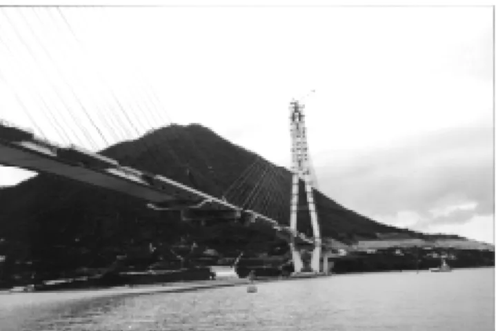
The Kurushima Bridges consist of three continuous sus-pension bridges with lengths of 960, 1,515, and 1,570 m (3,150, 4,970, and 5,151 ft). The main spans are 600, 1,020, and 1,030 m (1,969, 3,346, and 3,379 ft) long. The tallest towers have a height of 184 m (604 ft) above the top of their foundations. As shown in Figure 5, all three bridges were under construction during the visit. The target completion date is 1999. Kurushima 1, which was visited by the team, is shown in Figure 6. These bridges contain the following features:
• Basic wind speed of 40 m/sec (89 ft/sec) at 10 m (33 ft) height and a design wind speed of 51 m/s (114 mph) for Kurushima 1 and 53 m/s (119 mph) for Kurushima 2 and 3.
• Design for earthquake magnitude of 8.5 on the Richter scale.
• Poly-aramid fiber rope as the pilot rope.
• Main cables composed of strands made from 127 galva-nized steel wires approximately 5 mm (0.20 in.) in di-ameter with a tensile strength of 180 kgf/mm2 (256 ksi).
The number of strands per cable are 44 for Kurushima 1 and 102 for Kurushima 2 and 3.
• Erection sequence starting at midspan using hoists mounted on the main cables.
• Self-positioning barge for transportation and position-ing of deck sections below the bridge.
• Interlocking wire-wrapping system around the main cables.
• Stiffening girders consisting of a box girder section with orthotropic deck.
• Asphalt wearing surface.
• Fluoro-polymer and polyurethane paint systems. • Use of dry air system to reduce humidity inside the
cables.
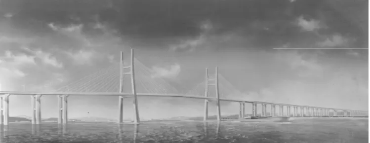
The Tatara Bridge, shown in Figure 7, is a cable-stayed bridge with span lengths of 270, 890, and 320 m (886, 2,920,
and 1,040 ft). Total width of the superstructure is 30.6 m (100 ft). The towers have a height of 220 m (722 ft) above their foundations. The bridge was originally designed as a suspension bridge but was later changed to a cable-stayed structure to avoid excessive earthworks that would have been required for an abutment. When completed, Tatara will be the world’s longest cable-stayed bridge. Features of the bridge include the following:
• Inverted Y-shaped steel towers with a slit in the upper two shafts. The basic shape was selected for aesthetic reasons. Details of the cross section were based on wind tunnel tests.
• Two planes of cables arranged in a fan pattern. • Prefabricated stay cables anchored in the pylon. Each
cable consists of galvanized steel wires and is coated with polyethylene in the prefabrication shop.
• Use of dimpled surface on the cable coating to reduce wind-induced oscillations.
• Use of steel girder with orthotropic steel deck for the superstructure of the main spans and prestressed
con-Figure 4. Vents to equalize air pressure on the Akashi-Kaikyo Bridge.
Figure 6. Kurushima 1 under construction. Figure 5. Kurushima Bridges under construction.
crete for the side spans between the intermediate and end piers. Concrete was used to balance the weight of the structure because the length of the main span cre-ates a dead load imbalance.
• Use of floating crane to erect deck segments.
Nippon Steel Corporation is Japan’s largest producer of crude steel and in 1996 had a total crude steel production of 25.3 million metric tons (27.8 million short tons). The cor-poration has eight blast furnaces. Three of the furnaces are located at the Kimitsu Works, which was visited by the team. The Kimitsu Works is situated near Tokyo on a site with a total area of 10 million m2 (3.9 mi2). Annual crude steel production in 1996 was 8.2 million metric tons (9.0 million short tons). The plant employs approximately 4,100 people. It was reported that 2 to 3 percent of their total budget is allocated for research on new applications. Some of the research involved projects that would benefit public bridge owners. The team visited the Steel Structures Development Center of the Research and Engineering Center, Blast Fur-nace No. 4, which has the capability of producing 11,000 tons per day, and associated steel production facilities.
In general, the site visit to the Nippon Steel Corporation’s Kimitsu Works revealed similar technology to major steel mills in the United States. The steel making operation began with a blast furnace to produce pig iron, a basic oxygen furnace to melt the steel, and a continuous caster to produce solid slabs. The rolling mill was also similar to U.S. practice, except for the addition of thermo-mechanical control processing (TMCP) equipment. The Kimitsu Works can produce steel plates with thicknesses from 4.5 to 200 mm (0.2 to 7.9 in.), widths from 0.9 to 4.5 m (3.0 to 14.8 ft), and lengths from 3 to 25 m (9.8 to 82.0 ft). It is larger than the plate-producing mills in the United States.
The following items were noted during the visit: • Research on the use of bolted beam-column
connec-tions for rectangular column members to improve their earthquake resistance. Full-scale tests of connections
under real-time dynamic displacements were being con-ducted.
• Research on the use of circular external rings to limit buckling of tubular columns. Tests under static and pseudo-dynamic loads were being conducted on re-duced-scale members to identify retrofit methods. • Research on concrete-filled steel tubes to limit damage
caused by earthquake loading.
• Vacuum degassing for all steels used in bridge con-struction.
• Thermo-mechanical control processing. • Continuous casting of steel.
The Yokogawa Bridge Corporation is one of Japan’s leading fabricators and erectors of steel structures for bridges, frames, and towers. The company was established in 1907 and has plants in Osaka and Chiba. The Chiba Plant was established in 1969 and occupies a land area of 132,146 m2 (32.7 acres). Production capacity is 4,000-5,000
metric tons/month (4,400 to 5,510 short tons/month). Com-ponents weighing as much as 200 metric tons (220 short tons) can be handled. It was indicated that the plant is a typical Japanese plant. It is qualified to construct major bridges in Japan and has the AISC Level III certification for major bridges in the United States. The plant has fabricated components for several bridges owned by HSBA and for bridges in the United States. The company also performs a large amount of work for steel buildings.
In general, the fabrication practices at the Chiba Plant were not significantly different from many operations in the United States. Submerged arc welding (SAW) appeared to be the dominant practice as is common in the United States. The same was true of many of the basic cutting and fit-up operations.
The following items were noted during the visit: • Implementation of CADD/CAM technology.
• Great emphasis on quality control of layout and toler-ances.
• Use of high heat input welding. • Three-wire welding for bridges. • Electro slag/electro gas welding.
• Nonmetallic removable back-up bars for one-sided welding.
• Computerized assembling test system.
South Korea
In South Korea, the team met primarily with representa-tives of the Korea Highway Corporation (KHC). Represen-tatives of the Korea Infrastructure Safety & Technology Cor-poration and Daiwoo Engineering Company were present during some of the meetings or site visits. Visits were made to the Seo-Hae Grand Bridge, the Kimp’o Grand Bridge, the Youngjong Bridge, and the POSCO Center in Seoul.
In South Korea, the Ministry of Construction and Trans-portation (MOCT) is responsible for administration, plan-ning, design, construction, and maintenance of all public roads. MOCT has the authority to develop the master plan for highways and to designate and manage national high-ways, except for the portions located within the jurisdiction of municipalities which are managed by the municipalities. The Bureau of Public Roads (BPR) of MOCT is the govern-ment agency responsible for policies related to public roads. All plans prepared by various agencies are reviewed by the BPR. At the end of 1996, the total length of roads in South Korea was 82,342 km (51,165 mi) of which 10,284 km (6,390 mi) have four lanes.
KHC is a government-financed organization formed in 1969. It has responsibility for twenty national expressways with a length of 1,840 km (1,143 mi). KHC plans to con-struct a grid-shaped expressway system in South Korea. This will double the present system to 3,500 km (2,175 mi) by the year 2004. Longer-range plans call for 6,000 km (3,728 mi) by the year 2020. Currently, KHC has a staff of approximately 5,000.
The Seo-Hae Grand Bridge, currently under construc-tion, is part of the Seo-Hae Coastal Highway that will con-nect the highly developed areas of Seoul with the west coast. The bridge will cross the Han-Gang River. The overall length of the bridge will be 7.31 km (4.54 mi), which will be the longest bridge in South Korea. The bridge will consist of the following three types of construction:
• A cable-stayed bridge with a length of 990 m (3,248 ft). • Precast concrete, constant depth, segmental bridges with
a length of 5,820 m (19,095 ft).
• Cast-in-place concrete, variable depth, box girder bridges with a length of 500 m (1,640 ft).
The cable-stayed bridge, shown in Figure 8, will have span lengths of 60, 200, 470, 200, and 60 m (197, 656, 1,542,
656, and 197 ft). The main span of 470 m (1,542 ft) will be the longest clear span in South Korea. The height of the two H-shaped pylons will be 182 m (597 ft) above the founda-tions. The steel segments for the superstructure will be de-livered by barge and lifted with a derrick crane. Precast concrete teams will then be installed on the steel segments and concrete placed to form a composite member. The cables will be arranged in two planes with 72 cables per plane. The cables will contain 15.2-mm (0.6-in.)-diameter parallel steel strands. The number of strands per cable will vary from 37 to 91. The strands will be coated with grease or wax on the inside of the anchorage. Cell-type cofferdams are being used for construction of the pylon foundations. This is the first application of its kind in South Korea.
The precast segmental bridges will consist of twin con-tinuous single cell boxes with span lengths of 60 m (197 ft). Each segment will have a width of 15.5 m (50.8 ft), a con-stant depth of 3.5 m (11.5 ft), and a length of 3 m (9.8 ft) for a total weight of 70 to 80 metric tons (77 to 88 short tons). The segments will be erected using the span-by-span method with a steel launching truss.
The cast-in-place, variable depth, box girder will have span lengths of 85, 165, 165, and 85 m (279, 541, 541, and 279 ft). Segment depth will vary from 3.5 to 9.0 m (11.5 to 29.5 ft). The segments will be erected using the balanced cantilever method. The completed structure will include movable facilities for inspection and maintenance.
The Kimp’o Grand Bridge, shown in Figure 9, will carry the Seoul Metropolitan outer ring road across the Han-Gang River. The bridge has a total length of 3.5 km (2.18 mi) with 2.28 km (1.42 mi) on elevated structure. The elevated portion includes the following types of construction:
• Cast-in-place concrete, constant depth, box girders con-structed using a movable formwork system with a total length of 950 m (3,116 ft).
• Cast-in-place concrete, variable depth box girder con-structed by the balanced cantilever method with a total length of 930 m (3,051 ft).
• Precast concrete, constant depth, box girders with a to-tal length of 400 m (1,312 ft).
A unique feature of the Kimp’o Grand Bridge is the length of 930 m (3,051 ft) between expansion joints at the end of the variable depth box girder section. Figure 10 shows a photograph of the expansion joint during installa-tion. Modular joints are used with center line splicing of transverse beams. Deck protection is provided by liquid membrane and asphalt overlay. Samples of strand couplers and anchorages were on display at the bridge site.
The Youngjong Bridge is part of the Inchon Interna-tional Airport Expressway that will connect the new airport to other major highways around Seoul and to the center of Seoul. The expressway is scheduled for completion in 2000. Travel time from the airport to downtown Seoul is expected to be about 45 min. At the time of the team visit, founda-tions for the bridge piers were under construction.
The Youngjong Bridge will have a total length of 4.42 km (2.75 mi). The main structure, depicted in Figure 11, will be a suspension bridge with span lengths of 125, 300 and 125 m (410, 984 and 410 ft). The two towers will be shaped like a diamond and will have a height of 107 m (351 ft). As a result of the sloping tower legs, the two main cables will have the shape of a traditional Korean roof line. The cables will be self-anchored to the stiffening truss. Cable protection will consist of zinc coating on the indi-vidual wires, a galvanized wrapping wire, and paint. The bridge is designed for tides of 10 m (30 ft), a current of 2.5 m/s (5.6 mph), and a wind speed of 40 m/s (89 mph). The superstructure will carry road traffic on the upper deck and rail traffic on the lower deck. It is reported to be the first bridge in the world to carry a 10-lane expressway and double-track railroad.
The visit to the POSCO Center provided the team with
Figure 9. Kimp’o Grand Bridge (Artist rendering cour-tesy of KHC).
the opportunity to review displays about steel production and steel products.
Taiwan
In Taiwan, the team met primarily with representatives of the Taiwan Area National Freeway Bureau and the Tai-wan Area National Expressway Engineering Bureau of the Ministry of Transportation and Communications (MOTC). Other organizations represented during team meetings in-cluded the Office of Science & Technology Advisers of MOTC, Department of Railways & Highways of MOTC, China Engineering Consultants, Inc., T. Y. Lin International, Dywidag Systems International, Kungsing Construction Corporation, National Taiwan University, and National Tai-wan University of Science and Technology. Site visits were made to the Kaohsiung-Pingtung (Kao-Ping) River Bridge and numerous other bridges in the Kaohsiung area of the Second Freeway Extension Project. In Taipei, a detailed description of the Hsichih-Wuku widening project was provided.
Figure 10. Installation of expansion joint on Kimp’o Grand Bridge.
The Taiwan Area National Freeway Bureau is respon-sible for road maintenance, traffic management, toll collec-tion, motorist services, and freeway widening. The Taiwan Area National Expressway Engineering Bureau has respon-sibility for planning, designing, and constructing the national expressway network in Taiwan. The Bureau is organized into the headquarters office and district project offices. The headquarters office is responsible for project planning, de-sign, land acquisition, bidding, and construction. The dis-trict project offices are responsible for the management of construction operations.
The Second Freeway Extension Project involves the construction of a 320-km (199-mi)-long main route plus four branch routes with a total length of 68 km (42 mi). The project includes the construction of 610 bridges and five
tunnels. Visits by the team were made to the Kao-Ping River Bridge on the main route and numerous bridges on the Kaohsiung Beltway and the Chishan Branch.
The main structure on the Kao-Ping River Bridge, de-picted in Figure 12, will be a single pylon cable-stayed bridge with span lengths of 330 and 180 m (1,083 and 591 ft). The inverted Y-shaped concrete pylon will have a total height of 180 m (591 ft). Foundations for the pylon were constructed using a slurry wall. The superstructure for the main span will be constructed with structural steel. The side span will be built with prestressed concrete. The struc-tural steel segments will be assembled using all-welded con-struction on site at an area adjacent to the pylon. The seg-ments will be erected by lifting from the superstructure. The concrete segments will be cast-in-place on a falsework
sys-Figure 11. Youngjong Bridge (Artist rendering courtesy of KHC).
tem and will be constructed before the main span segments are erected. At the time of the visit, about two-thirds of the inclined legs of the pylon had been constructed, as shown in Figure 13.
The stay cables will consist of a 15.2-mm (0.6-in.)-diameter seven-wire strand system produced by Vorspann Technik of Austria. In this system, the individual strands are coated with grease inside a polypropylene tube. The whole cable is enclosed inside a polypropylene tube that is filled with wax. Wedge anchors are used at the ends of the strands. When completed, the Kao-Ping River Bridge will be the longest span bridge in Taiwan.
Other bridges on the second freeway extension project are being constructed using the following systems:
• Constant depth, precast concrete segmental box girders erected by the balanced cantilever method with an erec-tion truss or cranes.
• Constant depth, cast-in-place concrete box girders con-structed span by span using an advancing shoring sys-tem.
• Constant depth, concrete box girders using the incre-mental launching method. Launching is accomplished by pulling the rear end of the bridge towards the abut-ment using strands.
• Variable depth, cast-in-place concrete segmental box girders erected by the balanced cantilever method and travelling formwork.
• Post-tensioned I-shaped concrete girders.
• A combination of precast concrete slabs and cast-in-place construction as illustrated in Figure 14.
For the balanced cantilever method with travelling formwork, the cantilevers were constructed with a one-half length of segment out of balance to reduce the overturning moment. End spans were also being constructed using form travellers and falsework towers.
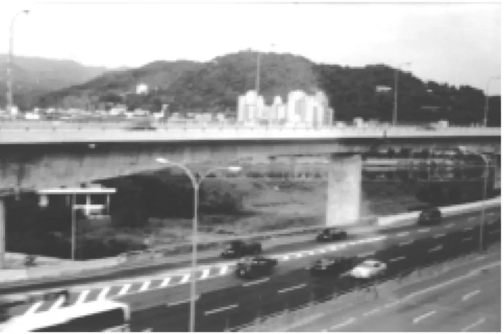
The Sun-Yat-Sen Freeway is a 373-km (232-mi) stretch of highway in northern Taiwan opened in 1978. Since that time, traffic on the freeway has grown at an annual rate of 10 percent. Additional lanes have been added using the center median and the shoulders to increase the capacity. However, further widening at grade level became impracti-cal. Consequently, it was decided to widen the freeway by adding elevated structures on each side of the existing free-way over a length of 21 km (13 mi). This project is known as the Hsichih-Wuku widening project. For 13.5 km (8.4 mi), two lanes were added on each side and for 7.5 km (4.7 mi) three lanes were added. The widening provided a means to separate long distance traffic from local traffic with long-distance traffic using the new construction, as shown in Figure 15. The overall cost of the project includ-ing land acquisition and compensation was reported to be NT$31.2 billion ($1.1 billion U.S. in September 1997).
Several different construction methods were used for the foundations of the 954 piers. These included reverse circulation drilled piles, full casing drilled piles, caisson foundations, precast piles, and shallow footings. The 40.4-km (25.1-mi) length of elevated structure used many
differ-Figure 13. Kao-Ping River Bridge under construction.
Figure 14. Combination of precast slabs and cast-in-place construction (Diagrams by MOTC). (a) Underside of struc-ture; (b) Cross section
(a)
ent structural types. Approximately one-third of the super-structure was built using prestressed concrete I-girders and about one-quarter used steel box girders. Other types in-cluded cast-in-place, segmental box girders built by the bal-anced cantilever method; cast-in-place, double-tee girders; precast concrete box girders; precast, prestressed single-tee girders; and hollow slabs.
In Taipei, the team visited the Freeway Traffic Surveil-lance and Control Center of the Taiwan Area National Free-way Bureau. The control center uses an “on-line real time” integrated system and uses automated monitoring of traffic conditions with roadside equipment, centralized processing and control systems, and information transmission and com-munications equipment.
Figure 15. Hsichih-Wuku widening project.
Nonsegregating Flowable Concretes
For the cable anchorages of the Akashi-Kaikyo Bridge, HSBA used a self-healing highly flowable nonsegregating concrete. The concrete mix included a low-heat cement, lime-stone powder, superplasticizer, and 40-mm (1.6-in.) maxi-mum size coarse aggregate. The concrete was specified to have a flow of 500 mm (120 in.), air content of 4 percent, and a 91-day compressive strength of 30 MPa (4,350 psi). Recommendation: The FHWA, in cooperation with State DOTs, should sponsor high-performance concrete demon-stration projects to show the advantages of using flowable concretes in areas of congested reinforcement. Information on this product should be made available to the American Concrete Institute, National Ready Mixed Concrete Asso-ciation, and the Portland Cement Association.
Computerized Assembly and Testing System (CATS) for Steel Components
The Yokogawa Bridge Corporation has developed a new computerized system to simulate erection of complicated structures and to eliminate the need for shop assembly of bridges. CATS uses photogrammetry methods with four cam-eras to take 3-D pictures of each element. The shape and dimensions of the members are obtained by linking the data from the cameras and other measuring devices. The members are then “shop assembled” in simulation on the computer screen using software developed for that purpose. Any cor-rections that need to be made to the members are identified. Actual measurements are compared with the design data to identify production errors. This innovation removes the need for shop assembly, while ensuring accuracy. In addition, in-formation, such as camber and joint widths, for assembling the bridge at the construction site is developed.
Recommendation: CATS should be studied further by the American Institute of Steel Construction, the American Iron and Steel Institute, and the National Steel Bridge Alliance, and research considered to develop a system that can be used in the United States. Copies of this scanning review report, including the translation of the CATS brochure, should be made available to trade associations for distribu-tion to their members.
Nonmetallic Removable Back-Up Bars for One-Sided Welding
HSBA makes use of steel bridge decks for all its major bridge projects. These are orthotropic bridge decks field welded from one side only. HSBA uses a temporary, non-metallic back-up bar attached to the bottom of the deck plate using adhesive strips on the bar. The bar has a concave surface on the side attached to the deck to allow some over-SUMMARY OF RECOMMENDED
TECHNOLOGIES
On the basis of the observations made during the scan-ning review, the team developed a list of 30 topics for pos-sible application by public and private agencies in the United States. The list was then divided into 6 high-priority, 7 medium-priority topics, and 17 other topics for consider-ation at a later date. A summary of the topics and recom-mendations for implementation are given in this section. More details of the technologies are given later.
High-Priority Topics
Dimple Pipe for Exterior of Stay Cables
Vibrations of stay cables can be a serious problem un-der certain weather conditions. On the Tatara Bridge in Japan, a black polyethylene pipe with a dimpled outer sur-face is used to reduce vibrations caused by wind and rain. Recommendation: The FHWA should make information about the pipe available to the U.S. bridge engineering community.
reinforcement on the bottom side of the weld. The bar can be easily removed for inspection of the weld after comple-tion. The back-up bar used in Japan appeared to differ from the ceramic bars available in the United States, and it was implied that the cost of the Japanese bars was much lower. Potentially, the use of a similar back-up bar with adhesive strips in the United States can provide cost-effective quality improvements in U.S. welding processes.
Recommendation: A research funding agency (e.g., the FHWA, NCHRP, or other organization), in cooperation with the American Institute of Steel Construction, American Welding Society, and the National Steel Bridge Alliance, should perform research to investigate one-sided welding using the nonmetallic back-up bars that are being used in Japan. Possible applications in the United States should be determined.
Dry Air Injection System for Corrosion Protection of Cables
The latest HSBA system for corrosion protection of the main cables of suspension bridges consists of the injection of dry air into the main cable interior. The goal is to keep the humidity level inside the cable below 40 percent. In addition to the use of this system on new suspension bridges that will not have any anti-corrosion paste installed, HSBA plans to retrofit suspension bridges that were constructed with an internal anti-corrosion paste. These built structures are quite similar to suspension bridges in service in the United States today.
Recommendation: A research-funding agency (e.g., the FHWA, NCHRP, or other organization) should perform a more detailed investigation of the dry air injection system to determine how it can be used on existing and future bridges in the United States. Although HSBA is using the concept for suspension bridges, its possible use in other applications such as cable-stayed bridges should be evaluated.
Special Paint Primer
In cooperation with major steel producers, PWRI has been testing and evaluating a significant improvement in cor-rosion protection technology. This technology is a new spray-on product that was referred to as “suspicious primer.” The spray-on primer product stimulates the formation of the chro-mium steels. This product was successfully tested by PWRI and sent to all major steel suppliers in Japan to have addi-tional independent testing conducted. Over the last year, test results have been positive. The product would be used on all bridge steels, regardless of grade and chemical make-up. The
product is commercially available from Sumitomo Metal Industries, Ltd., as the “Weather-Act Method.” Successful usage of this product has the potential to enhance protection practices of steel bridges in the United States.
Recommendation: The FHWA should obtain detailed in-formation about this product from Sumitomo Metal Indus-tries. If warranted, trial samples should be obtained and tested in the United States. Information should be made available to state DOTs.
Medium-Priority Topics
Balanced Cantilever Construction with Alternate Segments Offset by 1/2-Segment Length
The technique of constructing balanced cantilever cast-in-place concrete bridges with alternate segments offset by a 1/2-segment length is used in Taiwan to reduce the out-of-balance moment at the pier.
Recommendation: The FHWA should provide this scan-ning review report to the American Segmental Bridge Insti-tute (ASBI) for distribution to its members. Owners, design-ers, and contractors should consider using this technique in construction.
Full Cantilever Erection for End Spans of Balanced Cantilever Bridges
In Taiwan, it was noted that end spans were constructed using form travelers and the cantilever method. A tempo-rary pier was provided near midspan to allow the cantilever-ing to continue to the abutment. Hydraulic jacks were in-stalled between the temporary pier and the box girders to adjust for any settlements. This technique eliminated the need for continuous shoring that is frequently used in the United States.
Recommendation: The FHWA should provide this scan-ning review report to ASBI for distribution to its members. Owners, designers, and contractors should consider using this concept for end span construction of bridges erected by the cantilever method.
Nonseparating (Desegregating) Tremie Concretes
For the underwater concrete tower foundations of the Akashi-Kaikyo Bridge, a special nonseparating concrete was used. The concrete contained a high-range water-reducing admixture to achieve flowability and an anti-washout
ad-mixture to obtain viscosity. An anti-washout adad-mixture is available from at least one supplier in the United States, but is not used extensively.
Recommendation: The FHWA, in cooperation with state DOTs, should sponsor high-performance concrete demon-stration projects to show the advantages of using non-sepa-rating concretes for underwater construction. Information on this product should be made available to the American Concrete Institute, the National Ready Mixed Concrete As-sociation, and the Portland Cement Association.
19-Wire Prestressing Strands
The Japanese have developed 19-wire prestressing strand with diameters of 17.8, 19.3, 20.3, and 21.8 mm (0.70, 0.76, 0.80, and 0.86 in.). The strands consist of two concen-tric layers of wire wrapped around a center wire. Each con-centric layer consists of nine wires. The strand has a speci-fied minimum strength slightly less than Grade 270 strand. The largest strand has a minimum breaking strength of 3.1 times the strength of a 12.7-mm (0.5-in)-diameter Grade 270 strand. The 19-wire strand developed in Japan has potential application for transverse post-tensioning of bridge decks and prestressing high-strength concrete beams.
Recommendation: A research-funding agency (e.g., the FHWA, NCHRP, or other agency) should develop or under-take a research project to develop design information for use with 19-wire strand. Design recommendations for the AASHTO Specifications should be developed.
Wrapping Wire with Interlocking Cross Section
On the Kurushima Bridges, a wrapping wire with an S-shaped cross section, developed by Nippon Steel Corpo-ration, will be used to wrap the main cables. The cross section of the wire is designed so that the two legs of the S interlock. The interlocking provides a tighter seal against moisture penetration compared to wrapping with conven-tional wire having a circular cross section.
Recommendation: The FHWA, in cooperation with an owner, should pursue the use of interlocking wire on the next suspension bridge to be built in the United States.
Flame or Thermal Spray Metallizing
PWRI has been working with an improved thermal spray system. The new thermal spray system uses lighter equipment and considerably less heat. The primary
innova-tion is the metal used for the thermal spray, which is a 50:50 combination by volume of zinc and aluminum. It is ex-pected that this system offers the best alternative for thermal spray applications. At the present time, its use has been reserved for long-span bridges because of the high cost. Recommendation: The FHWA should incorporate tests of the improved thermal spray system and the 50:50 zinc-aluminum spray into existing research projects for methods of controlling corrosion.
Translation of Relevant Sections of the HSBA Specifications into English
HSBA has developed its own specifications for long-span bridges.
Recommendation: The FHWA should have relevant sections of the HSBA specifications translated into Eng-lish and distribute the translations to appropriate organiza-tions.
Other Topics
Research on Punching Shear Failure
In all three countries, the topic of punching shear fail-ures of bridge decks associated with cracking and fatigue was mentioned. Each country had a slightly different expla-nation for the mechanism.
Recommendation: A research-funding agency (e.g., the FHWA, NCHRP, or other organization) should support a research project to determine if punching shear failure caused by fatigue of concrete is a failure mode that needs to be considered in the design of bridges in the United States. If required, appropriate design recommendations for the AASHTO Specifications should be developed.
Bolted Connections for Earthquake Resistance
The Japanese are evaluating the use of bolted connec-tions to improve seismic resistance of steel structures. Recommendation: The American Institute of Steel Con-struction, American Iron and Steel Institute, FHWA, or Na-tional Science Foundation should evaluate this concept and consider initiation of a project to determine if the use of bolted connections in bridge structures or buildings will improve their seismic resistance. If appropriate, design pro-cedures should be developed.
Mechanical Damping Devices to Control Vibrations of Steel Towers
HSBA has incorporated tuned mass dampers into its bridge towers to control vibrations both during construction and during the service life of the bridge. In the United States, this technology has been limited to buildings. Recommendation: Owners and designers of tall bridge structures are encouraged to consider this approach for new structures and as a retrofit for existing structures,
Forced Vibration Tests on Completed Bridges
The response of large bridges to wind and earthquake loads is an important aspect of design. Design assumptions about actual dynamic characteristics, such as natural fre-quencies and damping characteristics, can be determined by forced vibration tests on completed bridges. Information can be used to improve design procedures.
Recommendation: A national research effort should be initiated to evaluate the benefit of full-scale dynamic testing of bridges in the United States.
Special Railway Expansion Joints for Flexible Long-Span Bridges
On the Kojima-Sakaide Route, which carries a railroad on the lower deck, special joints were needed to accommo-date rotation and longitudinal movements.
Recommendation: The FHWA or NCHRP should distrib-ute copies of this scanning review report to the AAR, the American Railway Engineering and Maintenance Associa-tion, and the FRA informing them about the railway expan-sion joints used by HSBA.
Pneumatic Caissons with Remote Control Equipment for Underwater Construction
Construction of each tower foundation for the Young-jong Bridge uses pneumatic caissons, six remote-controlled excavators, and closed-circuit television. Instrumentation is provided to measure water levels, current speed, caisson el-evations, and tilt. Construction is monitored and controlled from a separate control room.
Recommendation: The FHWA should provide this scan-ning review report and other information about the use of remote-controlled equipment for underwater construction to the state DOTs and contractor’s trade associations for distribution to their members.
Slurry-Wall Construction for Tower Foundations
On the Kao-Ping River Bridge, the foundation for the main pier was being constructed using slurry walls to carry the pier loads.
Recommendation: The technique of using slurry walls to transfer pier loads to bedrock should be considered by de-signers as an alternative foundation system to reduce the amount of excavation required.
High-Strength Silicon Steel Wire
In Japan, a high-strength silicon steel wire with tensile strength of 180 kgf/mm2 (256 ksi) has been developed for
use in suspension cables in long-span bridges. The cable was first used in the Akashi-Kaikyo Bridge. HSBA reported that the bridge design would have required four main cables with traditional strength wire. The high-strength silicon wire, in combination with a lower factor of safety for the cable, allowed the use of only two cables, thereby signifi-cantly reducing the weight and cost of the structure. Recommendation: The FHWA, in cooperation with wire producers, should conduct research to demonstrate the prop-erties of high-strength silicon wire for use in suspension cables and to evaluate its potential use in other applications.
Steels Containing a Higher Percentage of Nickel
The Japanese have a weathering steel that is essentially equivalent to U.S. steel grades A709-50W and 70W, respec-tively, with the exception that the nickel content is increased from about 0.3 percent to about 3 percent. Similar steels are available in the United States under the ASTM A710 speci-fication, but steels meeting this specification are not cur-rently allowed by AASHTO for use in bridges.
Recommendation: A research-funding agency (e.g., the FHWA, NCHRP, or other organization), should initiate re-search to evaluate corrosion-resistant steels currently avail-able under the ASTM A710 specification to determine their suitability for use in bridge structures. If it is determined that the properties are adequate, the AASHTO Materials Specifications should be modified to allow their use. This will give engineers another tool for use in difficult environ-ments.
Vibration Damping Steel Plates
The Japanese have produced a composite vibration damping steel plate that consists of a 0.15- to 0.3-mm (0.006- to 0.012-in.) layer of visco-elastic resin sandwiched
between two 2.3- to 10-mm (0.09- to 0.39-in.)-thick steel plates. In this plate, the shear deformation of the visco-elastic resin layer caused by the vibration has the effect of damping the vibration. The product was developed for use in structural members to reduce the noise emitted from el-evated highways and rail lines in dense urban areas. Recommendation: A research-funding agency (e.g., the FHWA, NCHRP, or other organization) should undertake a study to evaluate potential applications for the vibration damping steel plates and, if appropriate, conduct a demon-stration project.
Thermo-Mechanical Control Processing or Similar Technology
In the Nippon Steel Corporation Plant, thermo-mechani-cal control processing (TMCP) equipment was being used in the rolling mill. TMCP consists of applying accelerated cooling or direct quenching of the plates during the rolling process, resulting in plates with higher strength and tough-ness without increased alloy content. TMCP also allows the production of plates with lower carbon equivalent numbers, a property that greatly improves weldability. The result is that plates with yield strengths greater than 345 MPa (50 ksi) can be produced on line. On-line processing does not limit the length of plate that can be produced. Conventional off-line quenching and tempering can be used to obtain similar steel properties, but the process is more expensive to per-form and only a few U.S. fabrication shops apply this tech-nology to bridge construction. Current off-line quenching and tempering in the United States limits plate lengths to about 15 m (50 ft). This can increase the number of welded splices required to fabricate a bridge girder, thereby increas-ing cost.
Recommendation: The U.S. steel industry should be en-couraged to introduce TMCP or similar technology into its plants as a means of reducing the cost and improving the quality of high-performance steels.
Truss Elements that Taper to I-Sections at the End Connections
HSBA utilizes innovative truss elements in its stiffen-ing girders. These elements are fabricated as four-sided boxes or tubes. However, toward the ends of the sections, two of the four sides are transitioned into a single web sec-tion and the other two sides continue through to create a wide flange I-section that can be connected on two sides. The two sides greatly simplify the bolted connections at team points where multiple members come together. Recommendation: The FHWA or NSBA should initiate a
project to demonstrate how the use of truss elements that taper to two-sided I-section members at the end connections can greatly simplify and facilitate member connections in new and rehabilitated bridges.
HSBA Paint System
For protection of its steel structures from corrosive sea environments, HSBA has developed long-life coating sys-tems comprising either polyurethane or fluoro-polymer paints. The paint system is specified in the HSBA Painting Standard for Steel Bridges. This document, written in Japa-nese, was supplied to the team.
Recommendation: The HSBA Specification on Paint Sys-tems should be translated into English and the information evaluated. If warranted, trial samples of the paint should be obtained and tested in the United States. Information should be sent to all state DOTs with recommendations for use.
Asphalt Overlays for Orthotropic Steel Decks
The Japanese have many bridges with orthotropic steel decks protected by an asphalt system.
Recommendation: The FHWA or NCHRP should obtain more information about the specifications, performance, and cost-effectiveness of using only asphalt overlays to protect orthotropic steel decks. Recommendations should be made for use of this technique in the United States.
Built-In Access and Utilities for Bridge Inspection and Maintenance
On the HSBA bridges, built-in travellers, lifts, gantries, and catwalks are provided to facilitate close-up inspection and maintenance.
Recommendation: Bridge owners should put greater emphasis on requiring that this equipment be installed on major bridges in the United States during initial construc-tion. This will make frequent inspection of bridges more feasible and will simplify access for maintenance.
Repair Robot for Use in Inaccessible Areas
HSBA, in cooperation with the Japan Construction Methods and Machinery Research Institute, has developed a repair robot to travel over bolted steel surfaces of structures. The robot is equipped with a work-head assembly, magnetic wheels, and TV cameras.
Recommendation: The FHWA should evaluate potential applications of the HSBA robot on U.S. bridges and deter-mine if its use should be pursued.
Public Relations Programs for Major Projects
Many of the construction sites had excellent visitors’ cen-ters and excellent informational materials for distribution. Recommendation: Bridge owners and the FHWA should develop informational packages for all major bridge and roadway projects to promote public and professional aware-ness of the benefits of bridge and highway investments.
DESIGN STANDARDS, CODES, AND SPECIFICATIONS
Design standards, codes, and specifications in the three countries use an approach similar to that used in the United States. Design live loads are being driven upward by the need to design for heavier and multiple trucks. In Japan, special emphasis is now being given to seismic design. Specific items for each country are given in the following sections.
Japan
Design specifications for highway bridges in Japan are prepared by the Japan Road Association, which is equiva-lent to AASHTO. The specifications are developed by com-mittees in a similar manner to the AASHTO specifications.
The Highway Bridge Specifications consist of five parts:
1. General 2. Steel Bridges 3. Concrete Bridges 4. Substructures 5. Seismic Design
In general, bridge design in both concrete and steel is based on the allowable stress approach. However, seismic design is based on ultimate strength. The design specifica-tions reference Japanese Industrial Standards (JIS) for qual-ity control and mechanical properties of materials. The JIS used to be revised on a 10-year cycle. However, recent events have resulted in more frequent changes. When mate-rials not covered by JIS are used, technical experts are con-sulted and a committee review process is adopted. The
Highway Bridge Specifications apply to span lengths up to
200 m (656 ft) and are revised every 4 to 5 years. The seis-mic design specification was extensively revised after the Great Hanshin Earthquake in 1995.
A guideline for limit state design of concrete structures has been developed by the Japan Society of Civil Engineers (JSCE). Introduction of limit state design into practice has been limited because there are no specific criteria to deter-mine the appropriate load and resistance factors. For frac-ture critical steel members, no damage is allowed under ser-vice loads. Partial damage is allowed under unlikely events such as unexpected live loads and big earthquakes, but cata-strophic failure is not allowed. Redundancy with fracture critical members has not been well recognized and there are no provisions for redundancy. For seismic design, there are two levels. At Level I, the structure is designed to survive with no damage. At Level II, some damage is allowed. The Japanese have seen evidence of fracture of steel members from low cycle fatigue occurring as a result of seismic load-ing. Strains were in the range of 10 to 20 percent.
Since HSBA deals with combined road and railway bridges and with span lengths longer than 200 m (656 ft), they have developed their own design standards for super-structure design, wind-resistant design, seismic design, and substructure design. These standards allow the use of higher tensile strength steels. HSBA standards use the allowable stress design approach with some movement toward a limit states method which HSBA sees as an international ap-proach. The use of a lower factor of safety for the main cables of the Akashi-Kaikyo Bridge because of the high dead load reflects a limit states approach. A copy of the HSBA specifications in Japanese was given to the team.
South Korea
Codes and specifications in South Korea are revised mainly by the Ministry of Construction and Transportation on a cycle of about 6 years. The revisions are made by a committee that performs research work and reports to a specialist consultant team that develops the final revisions. The Ministry informs the relevant authorities for imple-mentation.
The design approach in South Korea is very similar to that in the AASHTO Standard Specifications for Highway
Bridges. However, 33 percent larger truck loads are used
due to the increasing number of larger sized vehicles in the country. Other design loads include ship impact and tem-perature gradients. Steel structures are designed using the permissible stress design method. Prestressed concrete structures are designed for service loads and then checked for factored loads. The Koreans anticipate that the load and resistance factor design method will be used in the future.
For seismic design, the country is divided into two zones for selection of acceleration factors. Single-mode analysis methods are generally used, but for structures re-quiring more complex analysis, multi-mode methods are used. The seismic design standards are in the process of being rewritten.
Taiwan
In Taiwan, bridge design is based on the Highway Bridge Specifications published by the Ministry of Trans-portation and Communications. Reference is also made to the AASHTO Standard Specifications for Highway Bridges and the CALTRANS Bridge Design Specifications Manual. The current specifications were developed in 1989. They are being updated and should be complete by 1999. It also appeared that the basic specifications are modified for spe-cific projects.
A live load equivalent to HS20-44 + 25% is used. The service load design method is used for foundation design. The load factor design method is used for columns. Ser-vice load design or load factor design is used for the super-structure.
Recommendations on Design Standards, Codes, and Specifications
The AASHTO LRFD Bridge Design Specifications may represent a model document that could be used in these countries as they move toward an LRFD design approach. The United States should stay current on the Japanese pro-visions for wind loads, water loads, scour, seismic design, and new materials. The team recommends that FHWA ar-range for the translation into English of the relevant sections of the HSBA specifications.
DESIGN AND CONSTRUCTION PRACTICES Japan
In Japan, it is a requirement that bridges and viaducts be constructed economically and effectively in a short period of time to meet the rapid increase in traffic. The team learned that JH and PWRI have been directed to lower costs by 10 percent and to introduce life-cycle costing. The team also observed that both gasoline taxes and tolls are relatively much higher than in the United States.
A breakdown of the various types of structures and their applicable span lengths as published by JH is given in Table 3. Steel structures are used for longer span lengths, whereas in the United States concrete is more competitive for longer span lengths.
Many of the superstructures of existing Japanese bridges are built of steel to reduce weight and the resulting seismic forces. These structures are typically plate girder bridges because of economy and ease of fabrication. Design is gen-erally based on noncomposite action between the concrete deck and steel girders because of ease of maintenance. Box girders are used where girder depth is limited and on small radius curves. Elevated viaducts are used extensively in urban areas because of the shortage of land. Steel
substruc-tures are used to minimize the size of the footprint. Great emphasis is placed on doing as much work as possible in the prefabrication plant and minimizing labor at the expense of material weight. For longer spans, truss bridges, cable-stayed bridges, and suspension bridges are used. A unique feature noticed on the HSBA routes was the use of continu-ous suspension bridges such as the Kurushima Bridges and Bisan-Seto Bridges and the use of continuous cable-stayed bridges such as the Hitsuishijima and Iwakurojima Bridges. Concrete bridges consist of reinforced concrete box girders, prestressed concrete composite girders, and pre-stressed concrete box girders erected using the cantilever method. Current emphasis is directed to methods of mecha-nizing the construction process to reduce labor requirements. Reinforced concrete box beams are used on expressways for bridges with span lengths of 15 to 17 m (49 to 56 ft). Pre-stressed concrete girders are the standard for bridges with span lengths of about 30 m (100 ft). For long span lengths, box girders constructed by the balanced cantilever method are used. The use of precast concrete segments is leading to shorter construction times.
For short span bridges, standard plans and details are used and the process is largely automated. Although it was difficult to obtain precise numbers, there is a trend toward the greater utilization of concrete superstructures as steel is becoming less competitive than precast concrete for span lengths of 60 to 100 m (200 to 330 ft).
During the design phase of special structures, several alternate types of bridges and construction methods are con-sidered but only one final design is prepared for bidding. HSBA makes a complete independent check on the analysis of all its major bridges. After award of the contract, only small changes may be proposed by the contractor. There is no incentive for contractors to submit alternative designs as major changes are only made by the owner and, in this situ-ation, the job price is recalculated and the contractor returns all savings. The Japanese have limited experience with value engineering and design-build contracts. In some situations, JH does the basic design and allows the contractor to do the detailed design. The usual bidding process also involves separate contracts for the substructure and the superstruc-ture, whereas for most bridges in the United States, only one contract is used. The use of two contracts was evident on several multi-span bridges where the substructures for many spans were complete but the superstructure erection was a long way behind.
Extradosed Concrete Bridges
JH has built and is considering many innovative struc-tures. Among the innovative types that it has developed is one described as the “Extradosed Concrete Bridge.” A pho-tograph of this type of bridge is shown in Figure 16. This bridge is similar in appearance to a small cable-stayed bridge but with a low tower height. However, the bridge is more
appropriately considered as a modification of a conventional precast concrete cantilever bridge type. The innovation takes the prestressing tendons outside the box’s cross-sec-tion and attaches them to a single tower. The prestressing cables are attached to the superstructure’s elements using cable-stayed bridge practice. The bridge resembles the Ganter Bridge in Switzerland except the cables are exposed in the Japanese version. This is a further evolution beyond current U.S. practice that utilizes external and internal ten-dons all located inside the cross section. Advantages of this concept include the ease and standardization of casting op-erations, reduced tower height, less stress range in the cables, and no necessity to adjust cable forces. Several bridges of this type are being designed in Japan. U.S. standardization efforts now being conducted by the American Segmental
Bridge Institute, the Precast/Prestressed Concrete Institute, and AASHTO should be made aware of this innovation for their consideration.
Collision Protection Systems for Ships and Piers
HSBA uses vessel collision systems designed to protect ships as well as bridge piers. In the United States, the pri-mary goal in the design of dolphins, fenders, and piers is to provide protection of bridge piers. Minimizing ship dam-age has not been a priority in design philosophy. Among the choices HSBA considers are cellular steel buffer systems and 1-m (3-ft)-long breakaway plastic rods adhered to the facing teams of their piers to absorb the collision impact of a TABLE 3 Span lengths of bridges in Japan