McDATA
®
4Gb SAN Switch
Legal and notice information
© Copyright 2006 Hewlett-Packard Development Company, L.P. © Copyright 2006 McDATA Corporation.
© Copyright 2006. This software includes technology under a license from QLogic Corporation. All rights reserved.
Hewlett-Packard Company makes no warranty of any kind with regard to this material, including, but not limited to, the implied warranties of merchantability and fitness for a particular purpose. Hewlett-Packard shall not be liable for errors contained herein or for incidental or consequential damages in connection with the furnishing, performance, or use of this material.
This document contains proprietary information, which is protected by copyright. No part of this document may be photocopied, reproduced, or translated into another language without the prior written consent of Hewlett-Packard. The information is provided “as is” without warranty of any kind and is subject to change without notice. The only warranties for HP products and services are set forth in the express warranty statements accompanying such products and services. Nothing herein should be construed as constituting an additional warranty. HP shall not be liable for technical or editorial errors or omissions contained herein.
Java™ is a registered trademark of Sun Microsystems, Inc. Linux® is a registered trademark of Linus Torvalds.
McDATA® is a registered trademark of McDATA Corporation.
Microsoft®, Windows®, Windows XP®, Windows Server 2000®, Windows Server 2003®, and Internet Explorer® are U.S. registered trademarks of Microsoft Corporation.
Motorola® is a registered trademark of Motorola, Inc.
Netscape Navigator® and Mozilla™ are trademarks or registered trademarks of Netscape Communications Corporation. PowerPC® is registered trademark of International Business Machines Corporation.
Red Hat is a registered trademark of Red Hat Software Inc. SANtegrity Enhanced™ is a trademark of McDATA Corporation. McDATA Web Server™ is a trademark of McDATA Corporation.
About this guide . . . 9
Intended audience . . . 9
Prerequisites. . . 9
Related documentation . . . 9
Document conventions and symbols . . . 10
HP technical support . . . 11
HP-authorized reseller. . . 11
Helpful web sites . . . 11
1 Command Line Interface Usage . . . 13
Logging in to the switch. . . 13
Opening and closing an Admin session. . . 14
Entering commands. . . 14
Getting help. . . 14
Setting page breaks . . . 15
Creating a support file . . . 15
Downloading and uploading files . . . 17
2 User Account Configuration . . . 19
Displaying user account information . . . 20
Creating user accounts . . . 20
Modifying user accounts and passwords . . . 21
3 Network and fabric configuration. . . 23
Displaying name server information . . . 24
Displaying the ethernet network configuration . . . 24
Configuring the ethernet port . . . 25
Verifying a switch in the network . . . 26
Verifying and tracing fibre channel connections . . . 26
4 Switch configuration . . . 27
Displaying switch information. . . 27
Switch operational information . . . 28
System process information . . . 29
Elapsed time between resets . . . 29
Configuration information . . . 30
Switch configuration parameters . . . 30
Zoning configuration parameters . . . 30
Security configuration parameters . . . 31
Hardware information . . . 32
Firmware information . . . 32
Managing switch services . . . 33
Managing switch configurations . . . 34
Display a list of switch configurations . . . 34
Activate a switch configuration . . . 34
Copy a switch configuration . . . 34
Delete a switch configuration . . . 34
Modify a switch configuration . . . 35
Back up and restore a switch configuration . . . 36
Creating the backup file . . . 36
Setting the date and time. . . 40
Resetting a switch . . . 41
Installing firmware . . . 41
Non-disruptive activation . . . 42
One-step firmware installation . . . 42
Custom firmware installation . . . 43
Managing switch feature upgrades. . . 44
Displaying feature licenses . . . 44
Installing a feature license. . . 45
5 Port configuration . . . 47
Displaying port information . . . 47
Port configuration parameters . . . 47
Port operational information . . . 48
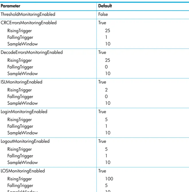
Port threshold alarm configuration parameters. . . 49
Port performance . . . 50
Transceiver information . . . 50
Modifying port operating characteristics . . . 51
Port binding. . . 52
Resetting a port . . . 53
Configuring port threshold alarms. . . 53
Testing a port. . . 55
Online tests for ports . . . 55
Offline tests for ports . . . 56
Display port tests results . . . 56
Cancel a port test . . . 56
6 Zoning configuration . . . 57
Displaying zoning database information . . . 58
Configured zone set information . . . 58
Active zone set information . . . 60
Zone set membership information . . . 60
Zone membership information . . . 61
Zoning modification history. . . 61
Zoning database limits . . . 62
Configuring the zoning database . . . 63
Modifying the zoning database . . . 64
Resetting the zoning database . . . 64
Removing inactive zone sets and zones. . . 64
Managing zone sets . . . 65
Create a zone set . . . 65
Delete a zone set. . . 65
Rename a zone set . . . 65
Add zones to a zone set. . . 65
Remove zones from a zone set . . . 65
Activate a zone set . . . 66
Deactivate a zone set. . . 66
Managing zones . . . 67
Create a zone. . . 67
Delete a zone . . . 67
Rename a zone . . . 67
Copy a zone. . . 67
Add members to a zone . . . 67
8 Device security configuration . . . 73
Displaying security database information. . . 73
Configured security set information . . . 74
Active security set information . . . 75
Security set membership information . . . 76
Group membership information . . . 76
Security database modification history . . . 77
Security database limits . . . 77
Configuring the security database. . . 78
Modifying the security database . . . 79
Resetting the security database. . . 79
Managing security sets . . . 80
Create a security set. . . 80
Delete a security set . . . 80
Rename a security set. . . 80
Copy a security set . . . 80
Add groups to a security set . . . 80
Remove groups from a security set . . . 80
Activate a security set. . . 80
Deactivate a security set . . . 80
Managing groups. . . 81
Create a group . . . 81
Delete a group . . . 81
Rename a group . . . 81
Copy a group . . . 81
Add members to a group . . . 82
Modify a group member. . . 82
Remove members from a group . . . 83
9 RADIUS server configuration . . . 85
Displaying RADIUS server information . . . 85
Configuring a RADIUS server on the switch . . . 86
10Event log configuration . . . 87
Starting and stopping event logging . . . 87
Displaying the event log . . . 88
Filtering the event log display . . . 89
Controlling messages in the output stream. . . 89
Managing the event log configuration . . . 90
Configure the event log . . . 90
Display the event log configuration . . . 90
Restore the event log configuration. . . 90
Clearing the event log . . . 91
Logging to a remote host . . . 91
Creating and downloading a log file . . . 92
11Simple Network Management Protocol configuration . . . 93
Managing the SNMP service . . . 93
Displaying SNMP information . . . 94
Modifying the SNMP configuration . . . 95
Resetting the SNMP configuration . . . 96
12Command reference . . . 97
Access authority . . . 97
Date command. . . 106
Exit command . . . 107
Fcping command . . . 108
Fctrace command . . . 109
Feature command. . . 110
Firmware Install command . . . 111
Group command . . . 113 Hardreset command . . . 119 Help command. . . 120 History command . . . 121 Hotreset command . . . 122 Image command . . . 123 Lip command . . . 126 Logout command . . . 127 Passwd command. . . 128 Ping command . . . 129 Ps command . . . 130 Quit command . . . 131 Reset command . . . 132 Security command . . . 139 Securityset command . . . 142
Set Alarm command . . . 144
Set Beacon command . . . 145
Set Config Port command . . . 146
Set Config Security command . . . 149
Set Config Security Portbinding command . . . 150
Set Config Security Switchbinding command . . . 151
Set Config Switch command . . . 153
Set Config Threshold command . . . 155
Set Config Zoning command . . . 157
Set Log command . . . 158
Set Pagebreak command. . . 161
Set Port command. . . 162
Set Setup Radius command . . . 163
Set Setup Services command . . . 165
Set Setup SNMP command . . . 167
Set Setup System command . . . 169
Set Switch State command. . . 171
Set Timezone command . . . 172
Show About command . . . 173
Show Alarm command . . . 174
Show Broadcast command . . . 175
Show Chassis command . . . 176
Show Config Port command . . . 177
Show Config Security command. . . 178
Show Config Switch command. . . 179
Show Config Threshold command . . . 180
Show Config Zoning command . . . 181
Show Domains command . . . 182
Show Fabric command . . . 183
Show FDMI command . . . 184
Show Interface command . . . 185
Show Port command . . . 197
Show Post Log command . . . 201
Show Setup Mfg command . . . 202
Show Setup Radius command . . . 203
Show Setup Services command . . . 204
Show Setup Snmp command . . . 205
Show Setup System command . . . 206
Show Steering command . . . 207
Show Switch command . . . 208
Show Timezone command . . . 210
Show Topology command . . . 211
Show Users command . . . 212
Show Version command . . . 213
Shutdown command . . . 214
Test Cancel command . . . 215
Test Port command . . . 216
Test Status command. . . 218
Uptime command . . . 219 User command . . . 220 Whoami command . . . 222 Zone command . . . 223 Zoneset command . . . 226 Zoning command . . . 228
Glossary . . . 233
Index . . . 237
Tables
1 Document conventions . . . 10 2 Command-line completion. . . 143 Factory user accounts . . . 19
4 Heartbeat LED activity . . . 32
5 Switch reset methods . . . 41
6 ISL Group member attributes . . . 115
7 Port Group member attributes . . . 116
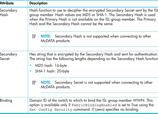
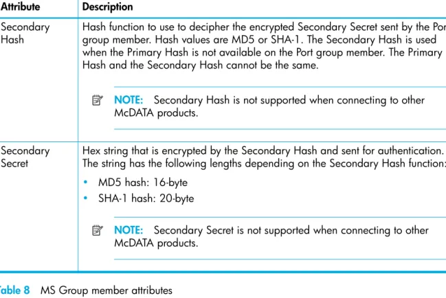
8 MS Group member attributes . . . 117
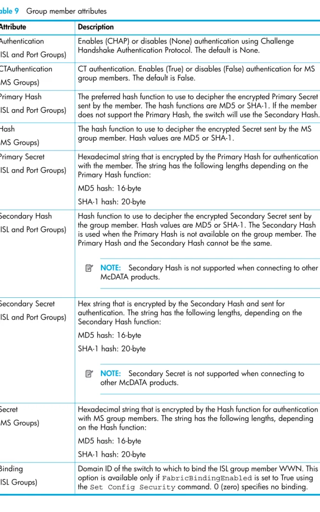
9 Group member attributes . . . 118
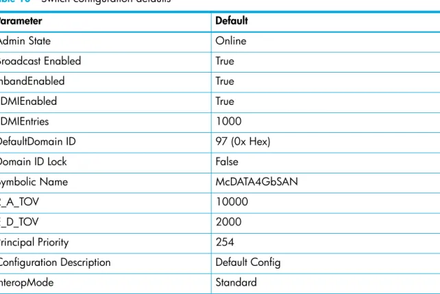
10 Switch configuration defaults. . . 135
11 Port configuration defaults. . . 136
12 Port threshold alarm configuration defaults . . . 137
13 Zoning configuration defaults . . . 138
14 SNMP configuration defaults. . . 138
15 RADIUS configuration defaults. . . 138
16 Switch services configuration defaults. . . 139
17 System configuration defaults . . . 139
18 Security configuration defaults. . . 140
19 Set Config Port parameters . . . 148
20 Set Config Security parameters . . . 151
21 Set Config Security Portbinding parameters. . . 152
22 Set Config Security Switchbinding parameters. . . 153
23 Set Config Switch parameters . . . 155
24 Set Config Threshold parameters . . . 157
25 Set Config Zoning parameters. . . 159
32 Port activity data . . . 200
33 Switch operational parameters . . . 210
34 Port test parameters . . . 218
About this guide
The McDATA 4Gb SAN Switch is a 10-port non-blocking Fibre Channel (FC) switch. This guide describes the Command Line Interface (CLI) management tool for the switch and defines its features, components, and performance characteristics.
The CLI is the focus of this guide which is organized as follows:
• ”Command Line Interface Usage” on page 13 describes logging on and off of a switch, opening and closing an Admin session, entering commands, getting help, paging a switch, setting page breaks, and loading and retrieving files.
• ”User Account Configuration” on page 19 describes the management of user accounts and passwords.
• ”Network and fabric configuration” on page 23 describes configuring the switch network connection.
• ”Switch configuration” on page 27 describes managing the switch configuration, setting the date and time, backing up and restoring the switch configuration, resetting the switch, installing firmware, and installing feature licenses.
• ”Port configuration” on page 47 describes port configurations, resetting a port, initializing a port loop, configuring port threshold alarms, and testing ports.
• ”Zoning configuration” on page 57 describes managing the zoning database and configuring interoperability.
• ”Connection security” on page 69 describes managing connection security.
• ”Device security configuration” on page 73 describes managing device security.
• ”RADIUS server configuration” on page 85 describes managing the Remote Authentication Dial-In User Service (RADIUS) server.
• ”Event log configuration” on page 87 describes events and event logging.
• ”Simple Network Management Protocol configuration” on page 93 describes managing the Simple Network Management Protocol (SNMP) configuration.
• ”Command reference” on page 97 lists the commands in alphabetical order, including the command syntax, operands, notes, and examples.
A glossary of terms and an index are also provided.
Intended audience
This guide introduces the CLI and explains its use. It is intended for users responsible for installing and using switch management tools.
Prerequisites
Prerequisites for using this product include:
• Knowledge of operating systems
• Knowledge of related hardware/software
Related documentation
In addition to this guide, please refer to the following documents for this product:
• McDATA 4Gb SAN Switch for HP p-Class BladeSystem release notesAA-RW1ZD-TE
• McDATA 4Gb SAN Switch for HP p-Class BladeSystem quick setup instructions A8001-90002
• McDATA 4Gb SAN Switch for HP p-Class BladeSystem installation guideAA-RW1XC-TE
• McDATA 4Gb SAN Switch for HP p-Class BladeSystem user guideAA-RW20C-TE
Document conventions and symbols
WARNING! Indicates that failure to follow directions could result in bodily harm or death.
CAUTION: Indicates that failure to follow directions could result in damage to equipment or data.
IMPORTANT: Provides clarifying information or specific instructions.
NOTE: Provides additional information.
TIP: Provides helpful hints and shortcuts.
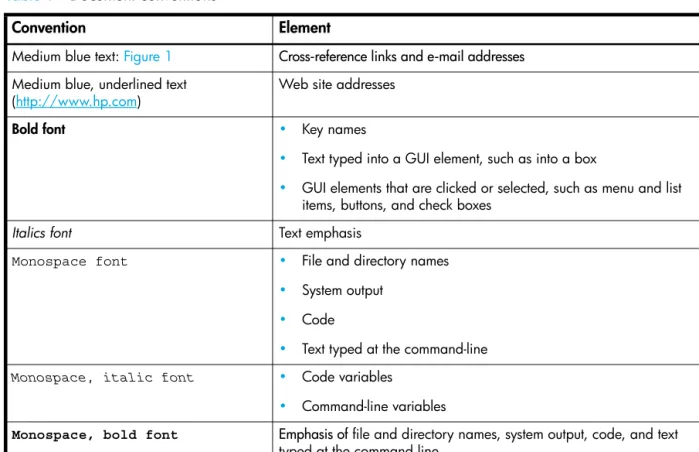
Table 1 Document conventions
Convention Element
Medium blue text: Figure 1 Cross-reference links and e-mail addresses
Medium blue, underlined text (http://www.hp.com)
Web site addresses
Bold font • Key names
• Text typed into a GUI element, such as into a box
• GUI elements that are clicked or selected, such as menu and list
items, buttons, and check boxes
Italics font Text emphasis
Monospace font • File and directory names
• System output
• Code
• Text typed at the command-line
Monospace, italic font • Code variables
• Command-line variables
Monospace, bold font Emphasis of file and directory names, system output, code, and text
HP technical support
Telephone numbers for worldwide technical support are listed on the HP support web site:
http://www.hp.com/support/.
Collect the following information before calling:
• Technical support registration number (if applicable)
• Product serial numbers
• Product model names and numbers
• Applicable error messages
• Operating system type and revision level
• Detailed, specific questions
For continuous quality improvement, calls may be recorded or monitored.
HP strongly recommends that customers sign up online using the Subscriber's choice web site:
http://www.hp.com/go/e-updates.
• Subscribing to this service provides you with e-mail updates on the latest product enhancements, newest versions of drivers, and firmware documentation updates as well as instant access to numerous other product resources.
• After signing up, you can quickly locate your products by selecting Business support and then Storage under Product Category.
HP-authorized reseller
For the name of your nearest HP-authorized reseller:
• In the United States, call 1-800-282-6672.
• Elsewhere, visit the HP web site: http://www.hp.com. Then click Contact HP to find locations and telephone numbers.
Helpful web sites
For other product information, see the following HP web sites:
• http://www.hp.com
• http://www.hp.com/go/storage
• http://www.hp.com/support/
1
Command Line Interface Usage
This section describes the following tasks:
• Logging in to the switch, page 13
• Opening and closing an Admin session, page 14
• Entering commands, page 14
• Getting help, page 14
• Setting page breaks, page 15
• Creating a support file, page 15
• Downloading and uploading files, page 17
NOTE: Throughout this document, references in text to commands and operands use initial capitalization for clarity. Actual command and operand entries are case insensitive
Logging in to the switch
To log in to a switch through Telnet, open a command line window on the workstation and enter the Telnet command followed by the switch IP address:
# telnet ip_address
The Telnet window opens prompting you for a login. Enter an account name and password. The default account name is Admin, and its password is password.
switch login: admin password: xxxxxxxx
NOTE: After logging in to the switch for the first time, you should change your password to insure switch security.
To log off, enter the Exit, Logout, or Quit command: McDATA4GbSAN #> exit
NOTE: A switch supports a combined maximum of 19 logins or sessions reserved as follows:
• 4 logins or sessions for internal applications such as management server and SNMP
• 9 high priority Telnet sessions
• 6 logins or sessions for McDATA Web Server inband and out-of-band logins, Application Programming Interface (API) inband and out-of-band logins, and Telnet logins.
Additional logins will be refused.
Opening and closing an Admin session
The command line interface performs monitoring and configuration tasks. Commands that perform monitoring tasks are available to all user accounts. Commands that perform configuration tasks are available only after entering the Admin Start command to open an Admin session. A user account must have Admin authority to enter the Admin Start command.
The following is an example of how to open and close an Admin session: McDATA4GbSAN #> admin start
McDATA4GbSAN (admin) #> .
. .
McDATA4GbSAN (admin) #> admin end
See the ”Admin command” on page 99.
Entering commands
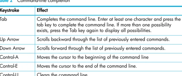
The command-line completion feature makes entering and repeating commands easier. Table 2 describes the command-line completion keystrokes.
Getting help
To display help for a command, enter the Help command followed by the command. The following is an example of the help that is available for the Config Edit command:
McDATA4GbSAN #> help config edit config edit [CONFIG_NAME]
This command initiates a configuration session and places the current session into config edit mode.
If CONFIG_NAME is given and it exists, it gets edited; otherwise, it gets created. If it is not given, the currently active configuration is edited. Admin mode is required for this command.
Usage: config edit [CONFIG_NAME]
See the ”Help command” on page 120.
Table 2 Command-line completion Keystroke Effect
Tab Completes the command line. Enter at least one character and press the tab key to complete the command line. If more than one possibility exists, press the Tab key again to display all possibilities.
Up Arrow Scrolls backward through the list of previously entered commands. Down Arrow Scrolls forward through the list of previously entered commands. Control-A Moves the cursor to the beginning of the command line
Control-E Moves the cursor to the end of the command line.
Setting page breaks
Some display commands deliver so much information to the screen that it scrolls off too quickly to read it. You can limit the display to 20 lines by turning on page breaks. By default, page breaks are turned off. The following is an example of how to turn page breaks on and off:
McDATA4GbSAN #> set pagebreak on McDATA4GbSAN $> set pagebreak off
See the ”Set Pagebreak command” on page 161.
Creating a support file
If you contact technical support about a problem with your switch, they may request that you create and send a support file. This support file contains all of the switch configuration information that can be helpful in diagnosing the problem. The Create Support command creates the support file (dump_support.tgz) on the switch. If your workstation has an FTP server, you can proceed with the command prompts to send the file from the switch to a remote host. Otherwise, you can use FTP to download the support file from the switch to your workstation.
The following example creates a support file and sends it to a remote host if your workstation has an FTP server:
McDATA4GbSAN #> create support
Log Msg:[Creating the support file - this will take several seconds] FTP the dump support file to another machine? (y/n): y
Enter IP Address of remote computer: 10.20.33.130 Login name: johndoe
Enter remote directory name: bin/support
Would you like to continue downloading support file? (y/n) [n]: y Connected to 10.20.33.130 (10.20.33.130).
220 localhost.localdomain FTP server (Version wu-2.6.1-18) ready. 331 Password required for johndoe.
Password: xxxxxxx
230 User johndoe logged in. cd bin/support
250 CWD command successful. lcd /itasca/conf/images
Local directory now /itasca/conf/images bin
200 Type set to I. put dump_support.tgz
local: dump_support.tgz remote: dump_support.tgz 227 Entering Passive Mode (10,20,33,130,232,133)
150 Opening BINARY mode data connection for dump_support.tgz. 226 Transfer complete.
43430 bytes sent in 0.292 secs (1.5e+02 Kbytes/sec) Remote system type is UNIX.
Using binary mode to transfer files.
221-You have transferred 43430 bytes in 1 files.
221-Total traffic for this session was 43888 bytes in 1 transfers. 221 Thank you for using the FTP service on localhost.localdomain.
See the ”Create command” on page 103.
If your workstation does not have an FTP server, enter the Create Support command to create the support file, and use FTP to download the support file from the switch to your workstation as shown in the following example:
McDATA4GbSAN #> create support
Log Msg:[Creating the support file - this will take several seconds] FTP the dump support file to another machine? (y/n): n
To download the support file from the switch to the workstation, perform the following procedure:
1. Open a terminal window and move to the directory where you want to download the support file.
2. Enter the FTP command and the switch IP address or symbolic name. >ftp 10.0.0.1
3. When prompted for a user and password, enter the FTP account name and password (images, images).
user: images password: images
4. Set binary mode and use the Get command to download the file (dump_support.tgz). ftp>bin
ftp>get dump_support.tgz
xxxxx bytes sent in xx secs. ftp>quit
Downloading and uploading files
There are several files that reside on the switch that you can download to the workstation for examination or for safekeeping. These files include the following:
• Backup configuration file (configdata)
• Log files (logfile)
• Support files (dump_support.tgz)
You can upload firmware image files or backup configuration files to the switch to reinstall firmware or restore a corrupted configuration. The switch uses FTP to exchange files between the switch and the workstation.
• See ”Installing firmware” on page 41 for information about installing firmware.
• See ”Back up and restore a switch configuration” on page 36 for information about backing up and restoring a switch configuration.
• See ”Creating and downloading a log file” on page 92 for information about creating a log file.
• See ”Creating a support file” on page 15 for information about creating a support file. To download a file from the switch to the workstation, perform the following procedure:
1. Enter the FTP command and the switch IP address or symbolic name. >ftp 10.0.0.1
2. When prompted for a user and password, enter the FTP account name and password (images, images).
user: images password: images
3. Set binary mode and use the Get command to download the file (configdata). ftp>bin
ftp>get configdata
xxxxx bytes sent in xx secs. ftp>quit
To upload a file from the workstation to the switch, perform the following procedure:
1. Enter the FTP command and the switch IP address or symbolic name. >ftp 10.0.0.1
2. When prompted for a user and password, enter the FTP account name and password (images, images).
user:images password: images
3. Set binary mode and use the Put command to upload the file (config_switch_169). ftp>put config_switch_169
xxxxx bytes sent in xx secs. ftp>quit
2
User Account Configuration
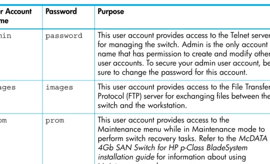
User accounts and their respective passwords are the first line of switch security. A user account consists of an account name, an authority level, and an expiration date. Switches come from the factory with certain user accounts defined for special purposes. Table 3 describes these accounts, their passwords, and their purposes. These accounts cannot be deleted from the switch.
This section describes the following user account configuration tasks:
• Displaying user account information, page 20
• Creating user accounts, page 20
• Modifying user accounts and passwords, page 21
Table 3 Factory user accounts User Account
Name Password Purpose
admin password This user account provides access to the Telnet server for managing the switch. Admin is the only account name that has permission to create and modify other user accounts. To secure your admin user account, be sure to change the password for this account.
images images This user account provides access to the File Transfer Protocol (FTP) server for exchanging files between the switch and the workstation.
prom prom This user account provides access to the
Maintenance menu while in Maintenance mode to perform switch recovery tasks. Refer to the McDATA 4Gb SAN Switch for HP p-Class BladeSystem installation guide for information about using Maintenance mode.
Displaying user account information
You can display all user accounts defined on the switch (User Accounts command) or just those user accounts that are logged on (User List or Show Users commands). Account information includes account name, authority, and expiration date.
The following example displays all user accounts defined on the switch: McDATA4GbSAN (admin) #> user accounts
Current list of user accounts
images (admin authority = False, never expires) admin (admin authority = True , never expires)
chuckca (admin authority = False, expires in < 50 days) gregj (admin authority = True , expires in < 100 days) fred (admin authority = True , never expires)
The following example displays user accounts that are logged on to the switch: McDATA4GbSAN (admin) #> user list
User Ethernet Addr-Port Logged in Since ---- ---
admin@OB-session1 10.20.68.108-1031 day month date time year admin@OB-session2 10.20.68.108-1034 day month date time year snmp@OB-session3 Unknown day month date time year snmp@IB-session4 Unknown day month date time year admin@OB-session5 Unknown day month date time year
See the ”User command” on page 220.
Creating user accounts
A user account consists of an account name, an authority level, and an expiration date. The account name can be up to 15 characters and must begin with an alphanumeric character. The authority level grants admin authority (true) or denies it (false). The expiration date sets the date when the user account expires. Only the Admin user account can create user accounts.
The following example creates a new user account named user1 with admin authority that expires in 100 days:
McDATA4GbSAN (admin) #> user add
Press 'q' and the ENTER key to abort this command. account name (1-15 chars) : user1
account password (8-20 chars) : ******* please confirm account password: *******
set account expiration in days (0-2000, 0=never): [0] 100 should this account have admin authority? (y/n): [n] y OK to add user account 'user1' with admin authority and to expire in 100 days?
Modifying user accounts and passwords
Only the Admin user account can modify a user account, delete a user account, or change the password of another user account. However, all user accounts can change their own passwords. The User command modifies and deletes user accounts. The Passwd command changes passwords.
The following example removes the expiration date and admin authority for the user account named user1:
McDATA4GbSAN (admin) #> user edit
Press 'q' and the ENTER key to abort this command. account name (1-15 chars) : user1
set account expiration in days (0-2000, 0=never): [0] should this account have admin authority? (y/n): [n] OK to modify user account 'user1' with no admin authority and to expire in 0 days?
Please confirm (y/n): [n]
The following example deletes the user account named user3: McDATA4GbSAN (admin) #> user delete user3
The user account will be deleted. Please confirm (y/n): [n] y
In the following example, the Admin user account changes the password for the user account named user2:
McDATA4GbSAN #> admin start
McDATA4GbSAN (admin) #> passwd user2
Press 'q' and the ENTER key to abort this command. account OLD password : ********
account NEW password (8-20 chars) : ******** please confirm account NEW password: ******** password has been changed.
3
Network and fabric configuration
The switch network configuration consists of the following:
• Network discovery method
• IP address
• Subnet mask
• IP gateway address
The network discovery method determines how the switch acquires its IP address. The IP address can come from the IP address that resides on the switch or from a server. The switch supports network discovery from the following server types:
• Bootstrap Protocol (BootP)
• Reverse Address Resolution Protocol (RARP)
• Dynamic Host Configuration Protocol (DHCP)
This section describes the following network configuration tasks:
• Displaying name server information, page 24
• Displaying the ethernet network configuration, page 24
• Configuring the ethernet port, page 25
• Verifying a switch in the network, page 26
Displaying name server information
The Show Ns command displays the domain ID information for the fabric as shown in the following example:
McDATA4GbSAN #> show ns all Seq Domain Port Port
No ID ID Type COS PortWWN NodeWWN --- --- --- ---- --- No entries found for domain ID 1.
Seq Domain Port Port
No ID ID Type COS PortWWN NodeWWN --- --- --- ---- --- No entries found for domain ID 4.
Seq Domain Port Port
No ID ID Type COS PortWWN NodeWWN --- --- --- ---- --- 1 8 (0x8) 0824ba NL 3 22:00:00:20:37:2b:08:00 20:00:00:20:37:2b:08:00 2 8 (0x8) 0824c3 NL 3 22:00:00:20:37:2b:08:78 20:00:00:20:37:2b:08:78 3 8 (0x8) 0824c5 NL 3 22:00:00:20:37:1b:cf:fd 20:00:00:20:37:1b:cf:fd 4 8 (0x8) 0824c6 NL 3 22:00:00:20:37:2b:07:b4 20:00:00:20:37:2b:07:b4 5 8 (0x8) 0824c9 NL 3 22:00:00:20:37:2b:08:57 20:00:00:20:37:2b:08:57 6 8 (0x8) 0824cb NL 3 22:00:00:20:37:1b:cf:f6 20:00:00:20:37:1b:cf:f6 7 8 (0x8) 0824cc NL 3 22:00:00:20:37:2b:0b:ec 20:00:00:20:37:2b:0b:ec 8 8 (0x8) 0824d6 NL 3 22:00:00:20:37:2b:07:e1 20:00:00:20:37:2b:07:e1 9 8 (0x8) 0824da NL 3 22:00:00:20:37:2b:0b:1a 20:00:00:20:37:2b:0b:1a 10 8 (0x8) 0824e0 NL 3 22:00:00:20:37:1b:f0:7d 20:00:00:20:37:1b:f0:7d 11 8 (0x8) 0824e1 NL 3 22:00:00:20:37:2b:02:f6 20:00:00:20:37:2b:02:f6 12 8 (0x8) 0824e2 NL 3 22:00:00:20:37:1b:ea:b7 20:00:00:20:37:1b:ea:b7 13 8 (0x8) 0824e8 NL 3 22:00:00:20:37:1b:cb:e5 20:00:00:20:37:1b:cb:e5 Seq Domain Port Port
No ID ID Type COS PortWWN NodeWWN --- --- --- ---- --- No entries found for domain ID 10.
Seq Domain Port Port
No ID ID Type COS PortWWN NodeWWN --- --- --- ---- --- No entries found for domain ID 34.
See the ”Show NS command” on page 193.
Displaying the ethernet network configuration
The Show Fabric command displays IP addresses (Enet IP Addr) for all switches in the fabric as shown in the following example:
McDATA4GbSAN #> show fabric
Domain WWN Enet IP Addr FC IP Addr SymbolicName --- --- --- 16 (0x10) 10:00:00:c0:dd:00:77:81 10.20.68.11 0.0.0.0 gui sb1 .11 17 (0x11) 10:00:00:c0:dd:00:6a:2d 10.20.68.12 0.0.0.0 sw12
The Show Setup System command displays the switch network configuration as shown in the following example:
McDATA4GbSAN #> show setup system System Information EthNetworkEnable True EthNetworkDiscovery Static EthNetworkAddress 10.20.11.32 EthNetworkMask 255.255.252.0 EthGatewayAddress 10.20.8.254 AdminTimeout 30 InactivityTimeout 0 LocalLogEnabled True RemoteLogEnabled False RemoteLogHostAddress 10.0.0.254 NTPClientEnabled True NTPServerAddress 51.68.85.102 EmbeddedGUIEnabled True
See the ”Show Setup System command” on page 206.
Configuring the ethernet port
Configure the switch Ethernet port using the Set Setup System command within an Admin session. The following example configures a new IP address, subnet mask, and gateway address:
McDATA4GbSAN (admin) #> set setup system
A list of attributes with formatting and current values will follow.
Enter a new value or simply press the ENTER key to accept the current value. If you wish to terminate this process before reaching the end of the list press 'q' or 'Q' and the ENTER key to do so.
EthNetworkDiscovery (1=Static, 2=Bootp, 3=Dhcp, 4=Rarp) [Static ]
EthNetworkAddress (dot-notated IP Address) [10.0.0.1 ]10.20.30.40 EthNetworkMask (dot-notated IP Address) [255.255.255.0]255.0.0.0 EthGatewayAddress (dot-notated IP Address) [10.0.0.254 ]10.20.30.254 AdminTimeout (dec value 0-1440 minutes, 0=never) [30 ]
InactivityTimeout (dec value 0-1440 minutes, 0=never) [0 ] LocalLogEnabled (True / False) [True ] RemoteLogEnabled (True / False) [False ] RemoteLogHostAddress (dot-notated IP Address) [10.0.0.254 ] NTPClientEnabled (True / False) [False ] NTPServerAddress (dot-notated IP Address) [10.0.0.254 ] EmbeddedGUIEnabled (True / False) [True ]
See the ”Set Setup System command” on page 169.
Verifying a switch in the network
You can verify that a switch is communicating in the network using the Ping command. The following example successfully tests the network for a switch with IP address 10.20.11.57:
McDATA4GbSAN #> ping 10.20.11.57
Ping command issued. Waiting for response... McDATA4GbSAN #>
Response successfully received from 10.20.11.57.
If the switch is unreachable, you will see the following display: McDATA4GbSAN #> ping 10.20.11.57
Ping command issued. Waiting for response... No response from 10.20.11.57. Unreachable.
See the ”Ping command” on page 129.
Verifying and tracing fibre channel connections
You can verify Fibre Channel connections between the switch and the fabric and display routing information. The target device can be defined as a Fibre Channel address or a World Wide Name (WWN). Enter the Fcping command to verify a Fibre Channel connection to a switch or a device as shown in the following example:
McDATA4GbSAN #> fcping 970400 count 3
28 bytes from local switch to 0x970400 time = 10 usec 28 bytes from local switch to 0x970400 time = 11 usec 28 bytes from local switch to 0x970400 time = 119 usec
The following is an example of a connection failure: SANbox #> fcping 0x113344 count 3
28 bytes from local switch to 0x113344 failed
Enter the Fctrace command to display Fibre Channel routing information between two devices as shown in the following example. The devices can be defined as Fibre Channel addresses or WWNs.
McDATA4GbSAN#> fctrace 970400 970e00 hops 5 36 bytes from 0x970400 to 0x970e00, 5 hops max
Domain Ingress Port WWN Port Egress Port WWN Port -- --- 97 20:04:00:c0:dd:02:cc:2e 4 20:0e:00:c0:dd:02:cc:2e 14 97 20:0e:00:c0:dd:02:cc:2e 14 20:04:00:c0:dd:02:cc:2e 4
See the ”Fcping command” on page 108. See the ”Fctrace command” on page 109.
4
Switch configuration
Switch configuration consists of the following tasks:
• Displaying switch information, page 27
• Managing switch services, page 33
• Managing switch configurations, page 34
• Switch binding, page 38
• Paging a switch, page 39
• Setting the date and time, page 40
• Resetting a switch, page 41
• Installing firmware, page 41
• Managing switch feature upgrades, page 44
Displaying switch information
You can display the following types of the switch information:
• Switch operational information, page 28
• System process information, page 29
• Elapsed time between resets, page 29
• Configuration information, page 30
• Hardware information, page 32
• Firmware information, page 32
Switch operational information
The Show Switch command displays a variety of switch operational information. This information includes the switch WWN, domain ID, firmware version, administrative state, and operational state, as shown in the following example:
McDATA4GbSAN #> show switch Switch Information
SymbolicName McDATA4GbSAN
SwitchWWN 10:00:08:00:88:e0:aa:b5
BootVersion V1.3.0.8.0 (Tue Mar 8 10:24:41 2006) CreditPool 0 DomainID 98 (0x62) FirstPortAddress 620000 FlashSize - MBytes 128 LogFilterLevel Info MaxPorts 10 NumberOfResets 4 ReasonForLastReset HotReset
ActiveImageVersion - build date V6.4.0.6.0 (Mon Mar 28 03:26:05 2006) PendingImageVersion - build date V6.4.0.6.0 (Mon Mar 28 03:26:05 2006) ActiveConfiguration default AdminState Online AdminModeActive False BeaconOnStatus False OperationalState Online PrincipalSwitchRole True BoardTemp (1) - Degrees Celsius 41 SwitchDiagnosticsStatus Passed SwitchTemperatureStatus Normal
See the ”Show Switch command” on page 208.
System process information
The Ps displays system process information to help you determine what processes are running and CPU usage. The following example displays current system processes:
McDATA4GbSAN #> ps
PID PPID %CPU TIME ELAPSED COMMAND 338 327 0.0 00:00:00 3-01:18:35 cns 339 327 0.0 00:00:01 3-01:18:35 ens 340 327 0.0 00:00:21 3-01:18:35 dlog 341 327 0.1 00:05:35 3-01:18:35 ds 342 327 0.2 00:11:29 3-01:18:35 mgmtApp 343 327 0.0 00:00:04 3-01:18:35 fc2 344 327 0.0 00:02:16 3-01:18:35 nserver 345 327 0.0 00:02:44 3-01:18:35 mserver 346 327 0.8 00:35:12 3-01:18:35 util 347 327 0.0 00:00:29 3-01:18:35 snmpservicepath 348 327 0.0 00:02:46 3-01:18:34 eport 349 327 0.0 00:00:21 3-01:18:34 PortApp 350 327 5.6 04:08:24 3-01:18:34 port_mon 351 327 0.0 00:01:38 3-01:18:34 zoning 352 327 0.0 00:00:01 3-01:18:34 diagApp 404 327 0.0 00:00:04 3-01:18:27 snmpd 405 327 0.0 00:00:02 3-01:18:27 snmpmain 406 405 0.0 00:00:00 3-01:18:26 snmpmain
The column titles are as follows:
• PID—Process identifier
• PPID—Parent process identifier
• %CPU—Percentage CPU usage
• TIME—Actual processing time
• ELAPSED—Elapsed time since the process started
• COMMAND—The command that initiated the process. See the ”Ps command” on page 130.
Elapsed time between resets
The Uptime command displays the elapsed time since the switch was last reset and the reset method. A hot reset or non-disruptive firmware activation does not reset the elapsed time reported by this command. The following example displays the time since the last reset:
McDATA4GbSAN #> uptime
Elapsed up time : 0 day(s), 2 hour(s), 28 min(s), 44 sec(s) Reason last reset: NormalReset
See the ”Uptime command” on page 219.
Configuration information
The Show Config command displays a variety of configuration information at the port and switch levels. In addition to the basic switch configurations, the Show Config command displays parameters that control how data is maintained in the security and zoning databases. The Show Config command displays the following types of information:
• Switch configuration parameters, page 30
• Zoning configuration parameters, page 30
• Security configuration parameters, page 31
See ”Displaying port information” on page 47 for details about displaying port configuration information.
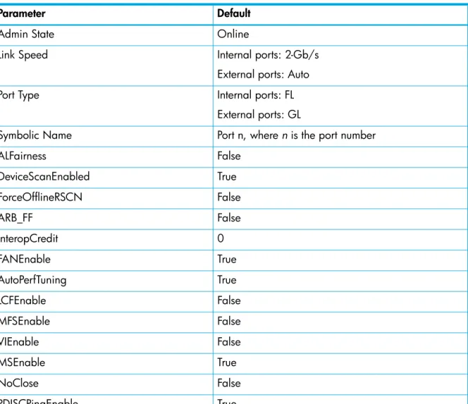
Switch configuration parameters
Enter the Show Config Switch command to display the switch configuration parameters. These parameters determine the operational characteristics of the switch. See Table 23 for a description these parameters.
McDATA4GbSAN #> show config switch Configuration Name: default AdminState Online BroadcastEnabled True InbandEnabled True FdmiEnabled True FdmiEntries 1000 DefaultDomainID 98 (0x62) DomainIDLock False SymbolicName McDATA4GbSAN R_A_TOV 10000 E_D_TOV 2000 PrincipalPriority 254
ConfigDescription Default Config ConfigLastSavedBy Initial
ConfigLastSavedOn Initial InteropMode Standard 239DomainSupport False
See the ”Show Config Switch command” on page 179.
Zoning configuration parameters
Enter the Show Config Zoning command to display zoning configuration parameters. These parameters determine how zoning is applied to the switch. See Table 25 for a description of these parameters.
McDATA4GbSAN #> show config zoning Configuration Name: default
Zoning Configuration Information InteropAutoSave True DefaultZone False
Security configuration parameters
Enter the Show Config Security command to display security configuration and port binding parameters. These parameters determine how security is applied to the switch. See Table 20 for a description of the switch security configuration parameters. See Table 21 for a description of the port binding parameters.
McDATA4GbSAN #> show config security Configuration Name: default
Switch Security Configuration Information FabricBindingEnabled False
AutoSave True Port Binding Status WWN - --
0 False 10:00:08:00:88:04:73:75
9 False No port binding entries found. 1 False No port binding entries found. 2 False No port binding entries found. 3 False No port binding entries found. 4 False No port binding entries found. 5 False No port binding entries found. 6 False No port binding entries found. 7 False No port binding entries found. 8 False No port binding entries found. Switch Binding Status WWN
Enabled - Fports 10:00:00:00:c9:4d:27:17 50:05:08:b2:00:b5:d2:73 50:05:08:b2:00:b5:db:33 50:05:08:b2:00:b6:3f:93 50:05:08:b2:00:7b:a7:e3 50:05:08:b2:00:7c:5b:93 10:00:08:00:88:04:73:75
See the ”Show Config Security command” on page 178.
Hardware information
Enter the Show Chassis command to display the status of the switch hardware including fans, power supplies, internal temperature, and Heartbeat LED status.
The following is an example of the Show Chassis command: McDATA4GbSAN #> show chassis
Chassis Information
BoardTemp (1) - Degrees Celsius 31 PowerSupplyStatus (1) Good HeartBeatCode 1 HeartBeatStatus Normal
The HeartBeatCode and HeartBeatStatus entries indicate the power-on self test (POST) results revealed by the Heartbeat LED blink patterns. The result is normal operation or a blink pattern indicating a critical error as described in Table 4. Refer to the McDATA 4Gb SAN Switch for HP p-Class BladeSystem installation guide for more information about the Heartbeat LED and its blink patterns.
See the ”Show Chassis command” on page 176.
Firmware information
Enter the Show Version command to display a summary of switch identity information, including the firmware version. The following is an example of the Show Version command:
McDATA4GbSAN #> show version
***************************************************** * * * Command Line Interface SHell (CLISH) * * * ***************************************************** SystemDescription McDATA 4Gb SAN Switch
EthNetworkAddress 10.20.94.50 (use 'set setup system' to update) MACAddress 00:c0:dd:07:12:1b WorldWideName 10:00:08:00:88:e0:aa:b5 ChassisSerialNumber 0508a00172 SymbolicName McDATA4GbSAN ActiveSWVersion V6.4.x.x.x ActiveTimestamp ddd mmm nn hh:mm:ss yyyy DiagnosticsStatus Passed ISLLicensedPorts All
Table 4 Heartbeat LED activity
HeartBeatCode—HeartBeatStatus Description
1—Normal One blink per second—Normal operation
2—AppDied Two blink cluster—Internal firmware failure
3—PostFailed Three blink cluster—System error
4—CorruptFilesystem Four blink cluster—Configuration file system error
Managing switch services
You can configure your switch to suit the demands of your environment by enabling or disabling a variety of switch services. You manage the switch services using the Show Setup Services and
Set Setup Services commands. See Table 27 for a description of the switch services.
Enter the Show Setup Services command to display the current switch service status as shown in the following example:
McDATA4GbSAN #> show setup services System Services TelnetEnabled True SSHEnabled False GUIMgmtEnabled True SSLMgmtEnabled False EmbeddedGUIEnabled True SNMPEnabled True NTPEnabled True CIMEnabled True FTPEnabled True MgmtServerEnabled True
See the ”Show Setup Services command” on page 204.
Enter the Set Setup Services command within an Admin session to configure the switch services as shown in the following example:
McDATA4GbSAN (admin) #> set setup services
A list of attributes with formatting and current values will follow.
Enter a new value or simply press the ENTER key to accept the current value. If you wish to terminate this process before reaching the end of the list press 'q' or 'Q' and the ENTER key to do so.
*Warning: If services are disabled, the connection to the switch may be lost. TelnetEnabled (True / False) [True ]
SSHEnabled (True / False) [False] GUIMgmtEnabled (True / False) [True ] SSLMgmtEnabled (True / False) [False] EmbeddedGUIEnabled (True / False) [True ] SNMPEnabled (True / False) [True ] NTPEnabled (True / False) [False] CIMEnabled (True / False) [True ] FTPEnabled (True / False) [True ] MgmtServerEnabled (True / False) [True ]
Do you want to save and activate this services setup? (y/n): [n]
See the ”Set Setup Services command” on page 165.
Managing switch configurations
Successful management of switches and fabrics depends on the effective use of switch configurations. The switch configuration determines the basic operational characteristics of the switch. A switch supports up to 10 configurations including the default configuration, which is named Default Config. The current switch operating characteristics are determined by the active configuration. Only one configuration can be active at one time.
Each switch configuration contains switch, port, port threshold alarm, and zoning configuration components. This section describes the following tasks for managing switch configurations:
• Display a list of switch configurations, page 34
• Activate a switch configuration, page 34
• Copy a switch configuration, page 34
• Delete a switch configuration, page 34
• Modify a switch configuration, page 35
• Back up and restore a switch configuration, page 36
Display a list of switch configurations
Enter the Config List command to display the configurations stored on the switch as show in the following example. Notice that the Config List command does not require an Admin session.
McDATA4GbSAN #> config list Current list of configurations default
config_1 config_2
See the ”Config command” on page 100
Activate a switch configuration
Enter the Config Activate command within an Admin session to activate a switch configuration (config_1) as shown in the following example:
McDATA4GbSAN (admin) config activate config_1 See the ”Config command” on page 100.
Copy a switch configuration
Enter the Config Copy command within an Admin session to create a copy of an existing configuration as shown in the following example:
McDATA4GbSAN (admin) config copy config_1 config_2 See the ”Config command” on page 100.
Delete a switch configuration
Enter the Config Delete command within an Admin session to delete a configuration from the switch as shown in the following example. You cannot delete the active configuration nor the default configuration (Default Config).
McDATA4GbSAN (admin) config delete config_2 See the ”Config command” on page 100.
Modify a switch configuration
To modify a switch configuration, you must open an Admin session with the Admin Start command. An Admin session prevents other accounts from making changes at the same time through Telnet, McDATA Web Server, or another management application. You must also open a Config Edit session with the Config Edit command and indicate which configuration you want to modify. If you do not specify a configuration name the active configuration is assumed. The Config Edit session provides access to the Set Config commands with which you make modifications to the port, switch, port threshold alarm, or zoning configuration components as shown in the following example:
McDATA4GbSAN #> admin start
McDATA4GbSAN (admin) #> config edit default The config named default is being edited.
McDATA4GbSAN (admin-config)#> set config port . . . McDATA4GbSAN (admin-config)#> set config security . . . McDATA4GbSAN (admin-config)#> set config switch . . . McDATA4GbSAN (admin-config)#> set config threshold . . . McDATA4GbSAN (admin-config)#> set config zoning . . .
The Config Save command saves the changes you made during the Config Edit session. In this case, changes to the configuration named Default are being saved to a new configuration named config_10132003. However, the new configuration does not take effect until you activate it with the Config Activate command:
McDATA4GbSAN (admin-config)#> config save config_10132003 McDATA4GbSAN (admin)#> config activate config_10132003 McDATA4GbSAN (admin)#> admin end
When you have finished making changes to the switch, the Admin End command releases the Admin session for other administrators. See the ”Admin command” on page 99. See the ”Config command” on page 100.
The following is an example of the Set Config Switch command. See Table 23 for a description of the switch configuration parameters.
McDATA4GbSAN #> admin start
McDATA4GbSAN (admin) #> config edit
McDATA4GbSAN (admin-config) #> set config switch
A list of attributes with formatting and default values will follow. Enter a new value or simply press the ENTER key to accept current value. If you wish to terminate this process before reaching the end of the list press 'q' or 'Q' and the ENTER key to do so.
AdminState (1=Online, 2=Offline, 3=Diagnostics) [Online ] BroadcastEnabled (True / False) [True ] InbandEnabled (True / False) [True ] FDMIEnabled (True / False) [True ] FDMIEntries (decimal value, 0-1000) [1000 ] DefaultDomainID (decimal value, 97-127) [2 ] DomainIDLock (True / False) [False ] SymbolicName (string, max=32 chars) [4Gb SAN Switch] R_A_TOV (decimal value, 100-100000 msec) [10000 ] E_D_TOV (decimal value, 10-20000 msec) [2000 ] PrincipalPriority (decimal value, 1-255) [254 ] ConfigDescription (string, max=64 chars) [Default Config] InteropMode (0=Standard, 1=McData Fabric Mode) [Standard ] 239DomainSupport (True / False) [False ]
Back up and restore a switch configuration
Backing up and restoring a configuration is useful to protect your work or for use as a template in configuring other switches. Backing up and restoring the switch configuration involves the following:
• Creating the backup file, page 36
• Downloading the configuration file, page 36
• Restoring the configuration file, page 36
Creating the backup file
The Config Backup command creates a file on the switch, named configdata. This file can be used to restore a switch configuration only from the command line interface; it cannot be used to restore a switch using McDATA Web Server or Element Manager.
McDATA4GbSAN #> config backup
The configdata file contains the following switch configuration information:
• All named switch configurations including port, switch, port threshold alarm, and zoning configurations components.
• All SNMP and network information defined with the Set Setup command.
• The zoning database includes all zone sets, zones, and aliases.
• The security database except the group primary and secondary secrets. See the ”Config command” on page 100.
Downloading the configuration file
You use FTP to download the configdata file to your workstation for safe keeping and to upload the file back to the switch for the restore function. To download the configdata file, open an FTP session on the switch and login with the account name images and password images. Transfer the file in binary mode with the Get command, as shown in the following example:
>ftp ip_address user:images password: images ftp>bin
ftp>get configdata
xxxxx bytes sent in xx secs. ftp>quit
You should rename the configdata file on your workstation with the switch name and date, for example, config_switch_169_10112003.
Restoring the configuration file
The restore operation begins with FTP to upload the configuration file from the workstation to the switch, then finishes with a Telnet session and the Config Restore command. To upload the configuration file, config_switch_169_10112003in this case, open and FTP session with account name images and password images. Transfer the file in binary mode with the Put command as shown in the following example:
ftp ip_address user:images password: images ftp> bin
ftp> put config_switch_169_10112003 configdata Local file config_switch_169_10112003
The restore process replaces all configuration information on the switch and afterwards the switch is automatically reset. If the restore process changes the IP address, all management sessions are terminated. Use the Set Setup System command to return the IP configuration to the values you want. To restore the switch, open a Telnet session (a new IP address may be required), then enter the Config Restore command from within an Admin session as shown in the following example:
McDATA4GbSAN #> admin start
McDATA4GbSAN (admin) #> config restore
The switch will be reset after restoring the configuration. Please confirm (y/n): [n] y
Alarm Msg: [day month date time year][A1005.0021][SM][Configuration is being restored - this could take several minutes !]
Alarm Msg: [day month date time year][A1000.000A][SM][The switch will be reset in 3 seconds due to a config restore]
McDATA4GbSAN (admin) #>
Alarm Msg: [day month date time year][A1000.0005][SM][The switch is being reset]
Good bye.
See the ”Config command” on page 100.
Switch binding
IMPORTANT: Switch binding is available only with the McDATA SANtegrity Enhanced PFE key. See ”Managing switch feature upgrades” on page 44 for more information about installing a PFE key. To obtain the McDATA 4Gb SAN Switch serial number and PFE key, follow the step-by-step instructions on the
firmware feature entitlement request certificate for the PFE key. You can obtain a PFE key from the web at:
www.webkey.external.hp.com.
Switch binding establishes up to 256 switches or devices that are permitted to log in to a particular switch. Switches or devices that are not among the 256 permitted switches are refused access to the switch. Furthermore, you can specify whether to enforce the list for all switches and devices (Allports), devices only (FPorts), or switches only (EPorts). You apply switch binding by modifying the switch
configuration as described in ”Modify a switch configuration” on page 35. Enter the
Show Config Security Switchbinding command to display the switch binding configuration as shown in the following example:
McDATA4GbSAN #> show config security Configuration Name: default
Switch Security Configuration Information FabricBindingEnabled False
AutoSave True Port Binding Status WWN - --
0 False 10:00:08:00:88:04:73:75
9 False No port binding entries found. 1 False No port binding entries found. 2 False No port binding entries found. 3 False No port binding entries found. 4 False No port binding entries found. 5 False No port binding entries found. 6 False No port binding entries found. 7 False No port binding entries found. 8 False No port binding entries found. Switch Binding Status WWN
Enabled - Fports 10:00:00:00:c9:4d:27:17 50:05:08:b2:00:b5:d2:73 50:05:08:b2:00:b5:db:33 50:05:08:b2:00:b6:3f:93 50:05:08:b2:00:7b:a7:e3 50:05:08:b2:00:7c:5b:93 10:00:08:00:88:04:73:75
The Set Config Security Switchbinding command is used to enable switch binding and to specify the WWNs of the authorized ports/devices. The following example enables switch binding for devices and switches, and specifies two WWNs.
McDATA4GbSAN #> admin start
McDATA4GbSAN (admin) #> config edit
The config named default is being edited.
McDATA4GbSAN (admin-config) #> set config security switchbinding A list of attributes with formatting and current values will follow.
Enter a new value or simply press the ENTER key to accept the current value. If you wish to terminate this process before reaching the end of the list press 'q' or 'Q' and the ENTER key to do so.
SwitchBindingEnable (True/False) [True ]
SwitchBindingState (AllPorts/EPorts/FPorts) [Fports] AllPorts
WWN (N=None/WWN) [None] 10:00:00:00:c9:4d:27:17 WWN (N=None/WWN) [None] 50:05:08:b2:00:b5:d2:73 WWN (N=None/WWN) [None ] Finished configuring attributes.
This configuration must be saved (see config save command) and activated (see config activate command) before it can take effect. To discard this configuration use the config cancel command.
See the ”Show Config Security command” on page 178.
See the ”Set Config Security Switchbinding command” on page 151.
Paging a switch
To help you locate a particular switch in a rack of switches, you can turn on the beacon feature with the Set Beacon command. This causes all port Logged-In LEDs to flash in unison. The following is an example of how to turn the beacon on and off:
McDATA4GbSAN #> set beacon on McDATA4GbSAN $> set beacon off
See the ”Set Beacon command” on page 145.
Setting the date and time
The switch date and time can be set explicitly using the Date command or can be set automatically through a Network Time Protocol (NTP) server. The Date command also displays the current time. Unlike the Date command, the NTP server also synchronizes the date and time on the switch with the date and time on the workstation. Synchronized date and time is required for Secure Socket Layer (SSL) connections. To use an NTP server, you must enable the NTP client on the switch and specify an IP address for the NTP server.
NOTE: To set the date with the Date command, the NTP client must be disabled. Enter the Date command to display the date and time as show in the following example:
McDATA4GbSAN #> date Mon Apr 07 07:51:24 200x
Enter the Date command in an Admin session to set the date and time as shown in the following example: McDATA4GbSAN #> admin start
McDATA4GbSAN (admin) #> date 013110152025 McDATA4GbSAN (admin) #> date
Fri Jan 31 10:15:03 UTC 2025
See the ”Date command” on page 106.
To configure the switch to use an NTP server, enter the Set Setup System command to enable the NTP client and to specify the NTP server IP address.
McDATA4GbSAN #> admin start
McDATA4GbSAN (admin) #> set setup system
A list of attributes with formatting and current values will follow.
Enter a new value or simply press the ENTER key to accept the current value. If you wish to terminate this process before reaching the end of the list press 'q' or 'Q' and the ENTER key to do so.
EthNetworkDiscovery (1=Static, 2=Bootp, 3=Dhcp, 4=Rarp) [Static ] EthNetworkAddress (dot-notated IP Address) [10.0.0.1 ] EthNetworkMask (dot-notated IP Address) [255.255.255.0] EthGatewayAddress (dot-notated IP Address) [10.0.0.254 ] AdminTimeout (dec value 0-1440 minutes, 0=never) [30 ] InactivityTimeout (dec value 0-1440 minutes, 0=never) [0 ] LocalLogEnabled (True / False) [True ] RemoteLogEnabled (True / False) [False ] RemoteLogHostAddress (dot-notated IP Address) [10.0.0.254 ] NTPClientEnabled (True / False) [False ] True NTPServerAddress (dot-notated IP Address) [10.0.0.254 ] 10.2.3.4 EmbeddedGUIEnabled (True / False) [True ]
Do you want to save and activate this services setup? (y/n): [n] y System setup saved and activated.
See the ”Set Setup System command” on page 169.
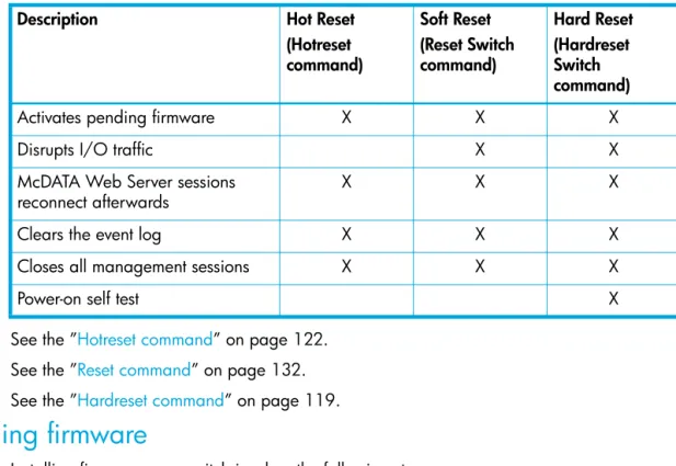
Resetting a switch
Table 5 describes the methods for resetting a switch, the corresponding command, and the impact on the switch.
See the ”Hotreset command” on page 122. See the ”Reset command” on page 132. See the ”Hardreset command” on page 119.
Installing firmware
Installing firmware on a switch involves the following steps:
1. Download the firmware image file to the switch.
2. Unpack the firmware image file.
3. Activate the new firmware. The activation can be disruptive or non-disruptive. See ”Non-disruptive activation” on page 42 for information about the conditions for a non-disruptive activation. The Firmware Install and the Image Install commands automate the firmware installation process and perform a disruptive activation as described in ”One-step firmware installation” on page 42. To perform a non-disruptive activation, see”Custom firmware installation” on page 43.
Table 5 Switch reset methods
Description Hot Reset
(Hotreset command) Soft Reset (Reset Switch command) Hard Reset (Hardreset Switch command)
Activates pending firmware X X X
Disrupts I/O traffic X X
McDATA Web Server sessions reconnect afterwards
X X X
Clears the event log X X X
Closes all management sessions X X X