3 handle / 2 exit thermostatic concealed shower
5 Year Warranty Terms & Conditions:
In the unlikely event that you should experience any defect in the materials or workmanship of your
new Abode product within FIVE years of purchase, the purchaser’s sole remedy shall be the
replacement (at the manufacturer’s discretion) of all or any part of the product that is defective.
Valves are guaranteed for a period of FIVE years from purchase. Decorative surface finishes and
O-rings are guaranteed for ONE year from the date of purchase provided that our advice concerning
care has been observed and no scouring agents have been used.
This is provided that the product has been used for normal domestic purposes in the UK and that the
care, installation and maintenance instructions have been observed. The warranty extends to the
original purchaser only. You should retain a copy of your dated invoice as proof of purchase to
validate any claims under this warranty.
Marks and scratches caused by improper installation or accidental damage are not covered by this
guarantee. Neither are shade variations or any damage or defect caused by incorrect installation or
abuse of the fitting.
As we are continuously improving and developing our products range, finishes & colours, in the event
of a valid claim, we may not be able to provide an identical replacement for the defective product
throughout the warranty period. Where an identical product is no longer available, we will supply the
nearest equivalent from our then current product range. In assessing your claim, we must be given
the opportunity to inspect the product as installed prior to removal. Any product returns must be
packaged carefully as received and complete.
No other warranties, express or implied, are made, including merchantability or fitness for a particular
purpose. Under no circumstances shall the manufacturer be liable for any loss or damage arising
from the purchase, use or inability to use this product, or for any special, indirect, incidental or
consequential damages. No liability is accepted for consequential damage to other household
fixtures, fittings or furnishings arising from this claim, even if attached to the product. No installer,
dealer, agent or employee of Abode has the authority to modify the obligations or limitations of this
warranty.
Product Care Instructions:
To maintain the appearance of this product, ensure that it is regularly cleaned only using a clean, soft
damp cloth. A solution of warm water and a mild liquid detergent may be used where necessary, and
then the fitting rinsed thoroughly and wiped dry. Any other cleaning action or cleaning products will
invalidate your warranty. Thermostatic Valves and particle filters should be cleaned to maintain flow.
Abrasive cleaners, scouring cleaners, limescale cleaners and acidic cleaners
must not be used
under any circumstances. Avoid contact with all solvents (including chlorinated solvents, ketones or
acetones as these may result in surface deterioration or etching). Also avoid contact with any harsh
household chemicals such as bleach cleaners, drain cleaners, rust removers, paint strippers and
toilet bowl cleaners, toothpaste, mouthwash, bar keepers friend or Brasso.
Installation Preparation:
All parts should be removed from their packaging and inspected for any transport damage and completeness prior to installation; you should read these instructions throughout before commencing installation.
We do not accept responsibility for problems that may occur through improper installation. Always ensure you have sufficient hot and cold water pressure available to allow correct function before specifying or installing this product. We strongly recommend installing particle filters and isolation valves to both the hot and cold feed pipes in an accessible position. This will help to prevent premature failure of the valves and ease any future maintenance.
Shut off your water heating system and ensure that your mains stopcock is closed. Ensure both the hot and cold water supplies are isolated before commencing installation.
1. Open the wall out to the required width and depth for the product and plumbing connections. If the rear wall surface is uneven or undesirable depth, then mount a level wood back board (B) to the wall to ease installation. The rear of the shower body (A) must be parallel with the finished wall surface.
All serviceable parts should be given suitable access to allow easy future maintenance.
When preparing the piping run to this shower, arrange the hot pipe to be received to the left hand inlet (E) when viewed from the front, as standard the outlets (G & H) will be above and below the shower body (A) as shown.
Note:
Valve body inlets are marked H (left) and C (right) and must be respected.
You should ensure that both the product and required fittings will fit into the depth and area of the mounting surface available before installation. Roughly assemble the product and plumbing connections to establish the required sizes ‘a-e’ below.
Diagram 1
Front
Wall
‘a’
Suggested aperture in tiled (front wall) surface = 125mm apx. Recommended (adjust according to preference)
‘b’
Suggested aperture in tiled (front wall) surface = 280mm apx. (adjust according to preference).You must leave Allen key access to grub screw (Y) when wall plate (N) is removed and also spanner access for valves
‘c’
Minimum Maximum 72mm78mm‘d’
Back board thickness‘e’
Minimum 68mm + (d)Note: You can adjust the cut-out shape ‘a’ and ‘b’ and size according to the tile size.
Diagram 2
Note: Fittings shown for Inlets (E & F) and Outlets (G & H) are not included. These are shown for illustration purposes only.
Key Description Qty.
(A) Shower body 1
(B) Back board 0
(C) Valve cap 2
(D) Thermo valve cap 1
(E) Hot inlet 1
(F) Cold inlet 1
(G) Outlet 1 1
(H) Outlet 2 1
(I) Screw 4
(J) Metal spacer 4 (K) Front rubber spacer 4 (L) Rear rubber spacer 4 (M) Screw fitting 4
Diagram 3
2. Fix inlet and outlet pipes securely to the wall using appropriate fixings. Inlet pipes should finish at the same height and be spaced as required.
Before installing the new shower, itis essential that you thoroughly flush through the supply pipes
in order to remove any remaining solder, swarf or impurities from your system. Failure to carry out this simple procedure could cause problems or damage to the workings of the shower and invalidate the warranty.
3. Attach ½” x 15mm compression fittings (not supplied) to all inlets and outlets ensuring to use PTFE tape to ensure a water tight seal.
4. Place the shower body (A) onto the rear wall or back board (B), mark the fixing holes through the fixing lugs. Note: Use a spirit level to make sure shower body (A) is fitted vertically as shown, and parallel to the front wall. 5. Assemble screw fitting (M) and rubber spacers (K & L) to all four lugs located on shower body (A) as shown in
diagram 3.
6. Screw (I) through the fixing lugs to the rear wall ensuring that metal spacer (J) is in place. Ensure the shower body (A) projects the required distance (Diagram 1‘c’) including any tile thickness to fit the shroud plate (N) before continuing. Ensure access to grub screw (Y) is possible once shroud plate (N) is installed. Any Adjustment
Installation Guidance:
1. Attach the 15 mm hot and cold supplies pipes (E, F) to the 1/2” x 15mm inlet compression fitting adaptors as shown.
2. Attach the 15mm outlet pipes for outlet 1 (G) and outlet (H) to the respective water outlet connections of the shower body (A). Note: (G) = Shower, (H) = Bath.
3. Test the water tightness of all inlet and outlet pipes and connections before progressing with the installation.
Note: This is best done by temporally blocking the outlet pipes and turning the shower on.
4. Complete the installation of outlet pipes to any final fittings.
5. With the on/off valve(s) in the open position pressure test for leaks all recessed connections before continuing, add a temporary outlet if needed to check the valve for flow rate and temperature mix function.
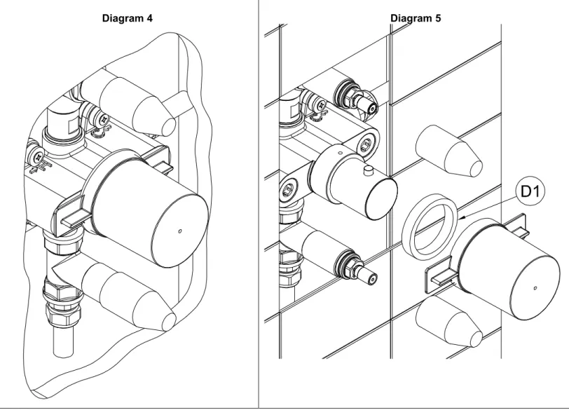
Diagram 4 Diagram 5
6. Make good the finished wall surface using tiles or similar, ensuring plastic valve caps (C & D) are in place as shown in Diagram 4 to protect decorative parts. The tiles must overlap the finished shroud plate (N) by at least 15mm on each side of the plate. Do not tile over the inlet mesh filter ports (A2) and allow access to grub screw (Y).
Note: Leave access to working parts for future maintenance. Ensure tile adhesive and grout are set before proceeding to next step.
7. Remove the plastic valve caps (C & D) as shown in Diagram 5.
Diagram 6
Key
Description
Qty.
Key
Description
Qty.
N Shroud plate (155 mm x 310mm) 1 R Grub screws 2
O Thermostatic handle (Handle may vary) 1 S Flow handles (Handles may vary) 2
P Thermostatic valve cover 1 T Valve cover 2
Q Dust caps 2 U Cover seal 2
8. Apply a continuous bead of sealant around the perimeter of the rear of wall plate (N).
9. Carefully push the shroud plate (N) onto shower body (A) over the thermostatic valve cover (P) flush to the finished wall.
Note: For certain models the thermostatic handle (O) will not be pre-assembled as shown. To fit the handle remove dust cap (V), push handle (O) over valve and limiting ring (X) ensuring stop button is facing upwards and tighten grub screw (W).
10. Screw valve covers (T) onto shower body (A) as shown ensuring seals (U) are in place and tight to wall plate (N) to make a water tight seal.
11. Ensure flow valve is closed (anti-clockwise), then push the handles (S) onto the flow control valves. Take care to place the flow control handles (S) in alignment in the off position.
12. Remove dust caps (Q) and tighten grub screws to fix handles (R). 13. Make sure dust caps (Q) are in place on handles (S) as shown.
14. Watchfully seal around the finished tiled wall surface and shroud plate (N) to prevent water ingress into the wall. Note take care not to apply sealant to parts of the shroud plate (N) that will be displayed, the shroud plate (N) can be temporally taped to the tiled wall whilst the sealant dries.
Thermostatic Handle Temperature Adjustment (optional stage):
Key Description Qty.
V Dust cap 1
W Grub screw 1
X Temperature limiting ring 1
WARNING: We recommend using this product as supplied with the factory set safe temperature (38°C). Any amendments made from the factory set temperature as shown may affect the safe use of this product.
1. Note the alignment black pen marks already on the brass and plastic sections of valve body. Using a marker pen mark the current position onto the limiting ring (X) adjacent to the black mark on the brass and section of the valve.
2. Remove handle (O) by removing dust cap (V) and loosening grub screw (W).
3. Pull temperature ring (X) away from shower body (A). Adjust the temperature ring (X) as desired.
Note: Adjust clockwise for hotter, anti-clockwise for colder.
4. Replace temperature ring (X) so that your newly made pen mark on the temperature ring (X) is adjacent to the black pen mark on the brass section of the valve.
5. Replace the handle (O), turn clockwise to reach the new stop position and then reassemble in reverse order.
After installation:
Once you have visually checked the installation of the new product and all connections, ensure that all other fittings are closed except the new product which should be left open. Turn on your water heating system and ensure that your mains stopcock is open. Reconnect both the hot and cold water supplies to this fitting.
Ensure all handles are firmly attached to shower valves by tightening any handle grub screws.
Check the function of flow and function of hot, cold and mixed water, where possible check the function of the thermostatic valve maximum temperature, and shut off function by interrupting the cold water source during use.
Turn off the product and check carefully for any leaks around all
connections on the fitting and adjoining plumbing. If possible return to the installation after a longer period to double check for slower leaks. If pressure testing equipment is available check the installation to the maximum recommended pressure.
Clean the product to remove any marks created during installation as instructed, now cover the product to protect the finish until it is ready for use.
Maintenance:
Thermostatic valve cleaning/replacement:
Key Description Qty.
Y Grub screw 1
A1 Thermostatic valve 1
Ensure both the hot and cold water supplies are isolated before commencing
cleaning/replacement.
To remove the thermo valve (A1) for cleaning, remove the grub screw (Y) under the thermo valve using a 3mm allen key. Pull the valve spindle away from the wall, descale and rinse or replace if needed. If enough room hasn’t been left to access grub screw (Y) shroud plate (N) may need to be removed first.
Ensure both the hot and cold water supplies are turned back on once complete.
Cleaning inlet mesh filters:
Key Description Qty.
A2 Inlet mesh filters 2
Ensure both the hot and cold water supplies are isolated before commencing cleaning.
1. Remove flow handles (S) by removing dust caps (Q) and loosening grub screws (R). 2. Unscrew valve covers (T) and pull away from
plate (N).
3. Carefully pull plate (N) away from wall. This will be siliconed in place and will need cutting first.
Note: Thermostatic handle (O) may need to be removed first dependant on model.
4. Remove inlet mesh filters (A2) for cleaning by unscrewing from shower body (A) using a 10mm allen key as shown.
5. Once cleaned assemble in reverse order making sure steps 8 – 14 are followed in the installation guidance section.
Ensure both the hot and cold water supplies are turned back on once complete.
Using This Product:
The upper handle controls the flow rate and is operated clockwise on, the lower handle controls
flow and is operated anticlockwise on.
The middle handle controls temperature and is operated clockwise on, the factory set maximum
temperature is 38°C (models with stop button) this can be overridden to a maximum of 42°C with the
button depressed.
Important Technical Data:
Minimum operating pressure 0.9 bar
Maximum operating pressure 5 bar*
Maximum hot & cold pressure differential 1.0 bar
Maximum cold water temperature 25°C
Minimum hot water temperature 60°C
Maximum recommended hot water temperature 80°C
Factory default maximum ‘safe zone’ output temperature 41-42°C
*Note: If these pressures are exceeded, even for short periods, damage can result. In these instances a
pressure reducing valve should be installed.
The incoming hot water temperature must be a minimum of 10°C above the outgoing water temperature to
ensure the correct function of the thermostatic cut off.
All thermostatic products should be tested and cleaned at least once a year, inlet mesh particle filters should
be periodically checked and cleaned to maintain flow. If access to mesh filters is not easy, then the filters
should be omitted from the installation as shown and included in a more accessible position.
When drilling or preparing walls take care not to disturb existing water or electrical supplies that may be
buried within the wall.
Supply pipes should maintain the maximum diameter until immediately before the fitting.
Hot and cold supply pressures should be as closely balanced as possible for best results. The differential
between the hot and cold water supply temperatures should be sufficient to allow correct mixing function; the
maximum hot / cold pressure differential ratio is 1.0 bar. Where pressures are greatly imbalanced flow
restricting valves or pressure reducing valves should be installed on the supply with the greater incoming
pressure.
Please ensure that your Abode product is fitted in accordance with Local Water Byelaws. Where hot and cold
water mix within any product, then suitable non return valves should be installed to the hot and cold supplies
to prevent backflow.
Whilst assembling this product take care not to accidentally loosen any screwed assemblies. PTFE tape can
be used to ensure watertight joins on threaded connections, do not over tighten connections or allow pipes to
be twisted or folded.
The installation should be periodically checked for damage, if the property is left unattended for a prolonged
period we recommend isolating water supplies.
All errors and omissions excepted.
Manufacturers Reference
©Abode 8/2020
Unit L, Zenith Park, Whaley Road, Barnsley,S75 1HT. Tel: 01226 283434 Fax: 01226 282434