Abstract— A biometric system provides automatic identification of an individual based on a unique feature or characteristic possessed by that individual. Iris recognition is regarded as one of the most reliable and accurate biometric identification systems available and has been receiving good acceptance in the area. This paper involves the development of iris recognition system using histogram analysis method backed by Local Phase Quantization (LPQ) and Rotation Invariant Local Phase Quantization (RI-LPQ) to verify the uniqueness of human iris as a biometric feature and to test its performances. Iris recognition system consists of the preprocessing process in which it involves image segmentation, feature extraction which includes the RGB image to grayscale and polar transformation. These preprocessed images were then undergone conversion process unto which histogram analysis via LPQ and RI-LPQ are taken place. From the histogram, it will be analyzed to determine and recognize other iris image. In order to implement the recognition, the machine learning process was set to be containing the iris image test database and iris image train database. The distance between the test and train images was measure using K Nearest Neighbor classifier algorithm. The result shows good recognition rate.
Index Terms— LPQ, RI-LPQ, K-NN, RGB, Histogram, Iris Recognition, Iris, Biometrics
I. INTRODUCTION
Iris recognition is a biometric technique to identify a person from the unique pattern contained in each iris. Similar with other biometric system such as fingerprint and face, the main purpose of iris recognition is to identify an individual by using the image of their iris. It is reported that iris patterns are characterize by high level of stability and distinctiveness. Each individual has a unique iris and the difference even exists between identical twins and between the right and left eye of the same person [1]. John Daugman [2] argued that iris can be a better biometric feature compared to face due to issues on relation between interclass and intra-class variability. This paper presents the matter pertaining on how
R. Abd. Rahim , Norhuda Othman , M.N.Shah Zainudin , N. A. Ali and M.Muzafar Ismail are serving in
Faculty of Electronic and Computer Engineering Universiti Teknikal Malaysia Melaka
Hang Tuah Jaya
76100 Durian Tunggal, Melaka, Malaysia
to identify iris of a person based on histogram analysis method via Local Phase Quantization (LPQ) and Rotation Invariant Local Phase Quantization (RI-LPQ).
Therefore the primary purpose of 'Iris Recognition', biometrical technology for personal identification and authentication, is to recognize a person from the iris unattended. The development of this 'Iris Recognition' used MATLAB owing from its ease image manipulation and wavelet applications. There is a high potential in improving the efficiency of the system as it only requires and process one dimensional signal processing.
The whole recognition system consists of 2 stages, one is the training a set of iris database and second stage is to perform iris recognition test on iris test database. Some of the images used in this research were taken from CASIA iris image database [1]. In the first stage, a training set of iris images are taken to undergone some preprocessing processes that involve iris image localization and segmentation, image conversion to grayscale and polar transformation. These images were then subject to LPQ and RI-PLQ method and consequently to get a histrogram data from the results and data obtained from preceding process. In recognition test, the test database images will also undergone the same processes in the same way as the training set, with an extension of comparing the data to those in the database. The performance of the system was evaluated in terms of percentage of accuracy in recognizing the iris image.
II. SEGMENTATION
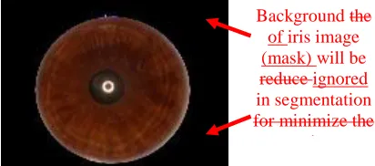
The first process is the segmentation of the distribution process of digital image into multiple segments of pixels. The goal of segmentation is to detect the part of the image that extends from inside the limbus (border between sclera and the iris) to the outside of the pupils [2]. In other words it is necessary to locate objects and boundaries (lines, curves) in iris images. Segmentation process in this project are used to get mask iris images from the original iris images in which it may need to be resized and crop the image to be used in further process.
In order to achieve this, edge detection algorithm is used to determine the location of the circular iris boundary. The image was first downsampled to a factor of two and the circular edge was obtained by using Canny method [3] with the default threshold value by Matlab.
Iris Recognition using Histogram Analysis via
LPQ and RI-LPQ Method
Fig.1. Original iris image before background removal.
Fig. 2. Iris image after segmentation process.
III. FEATURE EXTRACTION
A. Image Conversion in grayscale
Once the iris image only was obtained, it was then transformed into gray scale image. Gray scale image represents an image as a matrix where every element has a value corresponding to how bright or dark the pixel at the corresponding position should be color. There are two ways to represent the number that represents the brightness of the pixel:
The double class - This assigns a floating number, "a number with decimals" between 0 and 1 to each pixel. The value 0 corresponds to black and the value 1 corresponds to white.
The other class is called uint8 - Assigns an integer between 0 and 255 to represent the brightness of a pixel. The value 0 corresponds to black and 255 to white.
The class uint8 only requires roughly 1/8 of the storage compared to the double class. So, many mathematical functions can only be applied to the double class. In this stage, used the iris images from RGB to gray scale level and used the brightness of the pixel of the double class for double precision and facilitating the manipulation of the images in subsequent steps. Algorithm, pixel >150 -->2551 correspond to white, pixel <=150 0 correspond to black.
B. Polar Transform
After segmentation and conversion into grayscale level, the next step is to implement the transformation of rectangular image to polar form, called the Polar Transform. The output or mapping iris image is an MxN image with M points along the r axis and N points along the theta axis. Although not always correct, it is assumed that the outer edge of the iris is in
circular in shape and therefore the point of origin is at the center of the pupil [5]. Bilinear interpolation is used to interpolate between the points that is not really in the iris image.
The outer radius and inner radius which is denoted as rMin and rMax respectively must be between 0 and 1 and rMin <rMax. r = 0 is the center of the image, and r = 1 is half the width or height of the image. The purpose of this process is to obtain the iris mask that is practically needed to remove the unnecessary parts to get the right recognition. The size of the mapped image is fixed which means that we are taking an equal amount of points at every angle. As in Matlab M = 200, N = 500, rMin = 0, rMax = 1, imP = ImToPolar (imR, rMin, rMax, M, N). When the original image is transformed into polar form, it appears as a straight line segment as in Fig. 4.
Fig. 3. Original iris image in grayscale.
Fig. 4. Iris image in polar transform.
The next step of the process is to perform rotation invariant LPQ on the image. The process was first used and proposed by Ville Ojansivu et al [3] to analyst Blur Insensitive texture image. However we used the similar method with extension of histogram analysis in order to train and test the performance of iris images for personal identification. Before going to RI-LPQ, we presented first the LPQ.
C. Local Phase Quantization (LPQ)
The gray scaled polar image was considered as a blurred image. In image analysis, spatial blurring is represented by a convolution between the image intensity and a point spread function (PSF) [6]. the result of this image in frequency domain is a multiplication GFH. H, F and G are the PSF of the blurred image, original image and discrete Fourier transform (DFT) respectively. The phase of the spectrum the relation turns into a sum, GFH.
Since LPQ uses finite size 2-D discrete short term Fourier Transform (STFT) computed locally, H 0 at certain frequencies causing Fto be a blur invariant property. However this invariance is still pertinent and only small part of it is disturbed.
Background the of iris image (mask) will be reduce ignored in segmentation for minimize the
noise.
After segmentation process. Image of get the mask
In LPQ, the image is denoted as f(x) and the phase is examined in local neighbourhoods Nx at each pixel position
Tx x
X 1, 2 of the image. The computed local spectrausing a discrete STFT is defined by:
y u j R y T e x y y f x u
F( , )
( )
( ) 2(1) Where (x)is a window function and u is the frequency. The
local Fourier coefficients are computed at four frequency points at the complete equation of the vector
T
T
Ta a u a u a
u1 ,0 , 2 0, , 3 , , and
T
a a
u4 , . For
each pixel position this results in a vector.
, , ( , ), ( , ), ( , )
)
(x Fu1 x F u2 x Fu3 x F u4 x
F
(2) By examining the real and imaginary parts of F(x), the Fourier coefficients phase information can be obtained. This is done by performing a simple scalar quantization as in (3).
, , 0 0 , 1 otherwise g if
qj j
(3) Where qj is the j-th component of the vector
Re{ ( )},Im{ ( )}
)
(x F x F x
G . The result from this is qj that
consist of eight binary coefficients represented as integer values between 0-255. It is from these values that the histogram is composed and it used 256-colored vector in the classification process.
D. Rotation Invariant Local Phase Quantization (RI-LPQ)[Error! Bookmark not defined.]
There are two stages in the rotation invariant local phase quantization (RI-LPQ) method. First is estimation of orientation and the second stage is the extraction of directed descriptor.
Orientation Estimation
The rotated pupil’s image is denoted as f(x)'f(R1x)
where R is a 2-D rotation matrix equivalent to angle . In general the Fourier transform of f' is basically the Fourier
transform of f rotated by R . This is similar to other circular local neighborhoods Nx.
From this information, the coefficient in (1) on a circle of
radius r is estimated at frequencies vi r
cos(
i)sin(
i)
T, where i0,...,M1, and i 2i/M. The rectangularwindow R in (1) was replaced with circular Gaussian that is defined as ( ) 1/(2 )exp{ ( 22)/(2 2)}
2 1
2
G x x x
provided that x1 , x2 NR/2 and 0 otherwise.
As the result from these arguments, the resulting vector
)] , ( , ... ), , ( [ )
(x F v0 x F v 1 x
V M will be relocated tox', in the
case of rotation and it undergone circular shift that correspond
to the rotation angle
, within the discretization accuracy of2
/M. Apart from that, as a result of separability, V(x) is estimated for all image positions x using 1-D convolutions for the rows and columns consecutively.In order to also achieve distortion insensitivity, the phase of
V(x) was taken into account by observing the signs of the imaginary part of C(x)Im{V(x)} similarly to (3) for G(x). From the quantized coefficients, the characteristic orientation is extracted by using a complex moment in (4).
1 0 ) ( M i i j ie C x b (4) Where ci is the i-th quantized component of C(x). The orientation is defined for each pixel position by
) ( )'(x R 1x , where (y) is the orientation of NY from f. The approximation in used somehow in the equation is as a result of the discretization.
Therefore, an approximation scheme was taken into account
using a cosine function CˆA(x)cos(
(x)), with ]2 , 0
[
, where C(x) is interpolated using a cosine function, and the parameters A(x) and (x) are estimated using two
sample points [F(v0,x),F(vm/41,x)]. The orientation is then
derived as the position of the maximum value of Cˆ(x) i.e. )
( )
(x x
, with [0,2]. This is in accordance to the definition of the complex part in (4).
Computation of oriented LPQ
In this second stage, the vector of binary descriptor was extracted by using the vector of binary descriptor. The procedure presented here is almost comparable to the original LPQ, only that the neighborhood at each location is rotated to the direction of the orientation. For the rotated image f' is
defined as: ) , ( )) ( ( ) ( )' , ( )) ( ( ) ( )' , ( 1 2 1 1 ) ( 2 1 ) ( 1 ) 1 ( 1 1 ) ( x R u F y e x R t R t f x u F y e x y R y f x u F x R T x T R u j x R R y R u j x R
(5)In actuality RyRRy and tR1y. For RI-LPQ,
) (x
F was defined by replacing the oriented coefficients
) , (u x
F i into F(ui,x) in equation (2). In order to obtain the
256 dimensional descriptor vector, F(x)was used instead of )
(x
F the same way as in LPQ.
exponentials was computed. It is by this mean that the computational complexity can be properly optimized to be closed to the standard LPQ.
Fig. 5. Produce the histogram using LPQ method
IV. MACHINELEARNING
Machine learning is the process of generating some representation of the iris that is to be stored in the database to be used in recognition. A set of the original iris image database has 96 images divided into 32 images with an image for testing database and 64 images for training database in the visible range; RGB was selected at random from the Internet and processed using Matlab running in a personal computer (Intel Core i3 Processor). The selection criterion was to select different iris images in terms of shapes, color and illuminations. Resolution of the original iris images were 700x500 in PNG format. Before the recognition process the entire database in iris train database should be already train for the recognition process in the system. Therefore, the process must be done in this state.
V. RECOGNITION
As output iris image is presented to the system called the recognition process, after complete the feature extraction process. Recognition its normalized histogram is then
compared to each template in the iris image training database to determine if there is a match.
The algorithm used for recognition is K Nearest Neighbour classifier (K-NN). In this system for recognition used the
classified based on training database. For, xuD find the K ―closest‖ labelled examples in the training database and assign
xu to the class that appears most frequently within the K-subset.
The K-NN only requires:
An integer k
A set of labelled examples
A measure of ―closeness‖
VI. RESULTANDPERFORMANCE
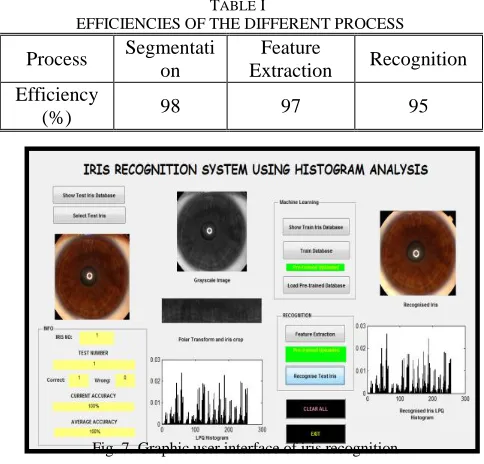
We tested our project on 32 iris images in 64 iris train images, using a Core i3 processor, and we obtained an average of correct recognition of 95%, with an average computing time of 0.6 seconds. Then, feature extraction process with an average computing time of 177 seconds. Table 1 gives the efficiency of each part of the system. The main reason of the system becomes 95% accuracy because the LPQ and RI-LPQ method is very suitable for iris recognition as it provides excellent data distribution on histogram. Based on the result, this technique can be considered as comparible to other proposed methods such by using histogram analysis alone [Error! Bookmark not defined.], PCA based technique [1], wavelet features [2], and using Ridgelet and Curvelet Transform [3].
TABLE I
EFFICIENCIES OF THE DIFFERENT PROCESS
Process Segmentati on
Feature
Extraction Recognition Efficiency
(%) 98 97 95
Fig. 6. Diagram of iris recognition methodology. Fig. 7. Graphic user interface of iris recognition
VII. GRAPHICUSERINTERFACE
and chose eye image. Then, user can choose the process of feature extraction combination process of grayscale image, polar transform and LPQ histogram in this stage. Finally, recognition select button can be used to recognize iris. Prior to this process the iris image need to be trained in the database. Therefore, user can use this built in interface to communicate with the system and can learn about the recognition process with ease.
VIII. CONCLUSIONS
We have successfully developed a new Iris Recognition system capable of comparing many digital eye-images. This identification system is quite simple requiring few components and is effective enough to be integrated within security systems that require an identity check. The errors that occurred can be easily overcome by the use of stable equipment. Judging by the clear distinctiveness of the iris patterns by using this method, we can expect iris recognition systems to be the leading technology in identity verification. It is believed that further research can be made such as trying other variation of measuring image distance techniques and image enhancement in the preprocessing stage.
REFERENCES
[1] C. H. Daouk, L. A. El-Esber, F. D. Kammoun and M. A. Al Alaoui,
“Iris Recognition”, Electrical and Computer Engineering
Department, Faculty of Engineering and Architecture American University of Beirut, Lebanon.
[2] J. Daugman, ―How Iris Recognition Works‖, University of Cambridge, The Computer Laboratory, Cambridge, UK.
[3] CASIA Iris Image Database, http://biometrics.idealtest.org.
[4] Wildes, R. P, ―Iris Recognition: An Emerging Biometrics
Technology‖, Proceedings of the IEEE, VOL. 85, NO. 9, September
1997, pp. 1348-1363
[5] R. W. Ives, A. J. Guidry and D. M. Etter, “Iris Recognition using
Histogram Analysis”, IEEE Transaction on Signals, Systems &
Computers, Electrical Engineering Department, U.S. Naval Academy Annapolis,2004.
[6] V. Ojansivu, E. Rahtu, J. Heikkila, “Rotation Invariant Local Phase
Quantization for Blur Insensitive Texture Analysis.” Machine Vision
Group, University of Oulu, Finland
[7] S. Kumar D R, K B Raja, R. K Chhootaray, S. Pattnaik, “PCA based Iris Recognition using DWT”, Int. J. Comp. Tech. Appl., Vol 2 (4), 884-893
[8] J. Kim, S. Cho, J. Choi, ―Iris Recognition Using Wavelet Features‖,
Journal of VLSI Signal Processing 38, 147–156, 2004
[9] M. Najafi and S. Ghofrani1, ―Iris Recognition Based on Using
Ridgelet and Curvelet Transform”, Electrical Engineering
Department, Azad University, South Tehran Branch, Tehran, Iran. [10] L. Masek, “Recognition of Human Iris Patterns for Biometric
Identification”, Computer Science and Software Engineering, the
University of Western Australia, 2003.
[11] O. Rodriguez and A. Pacheco, “Applications of Histogram Principal
Components Analysis, [Online] Available :
http://www.oldemarrodriguez.com.
[12] G.Padmavathi and Muthukumar, “Image segmentation using fuzzy c
means cluster- ing method with thresholding for underwater